Note: Descriptions are shown in the official language in which they were submitted.
REMOVABLE DENTURE
BACKGROUND OF THE INVENTION
Field of the Invention
[0001] The invention relates to a removable denture.
Description of the Related Art
[0002] The wear of conventional full-mouth removable dentures on an upper
jaw or a
lower jaw mainly relies on adhesion force which is created by saliva between
the artificial
full-mouth removable denture and oral mucosa, and friction force which is
created between
material of the removable denture and oral mucosa. However, when people are
chewing,
the dentures on the upper jaw tend to fall off, and the dentures on the lower
jaw are easily
dislocated and moved. In order to generate a negative pressure effect similar
to a suction
cup, some vendors will provide a removable denture comprising a concave
circular space
formed corresponding to a middle portion of a palatine bone of the upper jaw.
However,
since the gas venting structure for decompression is not provided in the
removable denture
no vacuum-negative pressure is generated on such a removable denture, and the
desired
effect of suction-cup like negative pressure is thus theoretically impossible
to be found.
Other vendors provide a removable denture comprising a gas exhausting device
in the
aforementioned concave circle space. However, the gas exhausting device
stimulates oral
mucosa to grow up in the concave circle space and finally block the whole
concave circle
space. In addition, when the mouth is chewing, the movable mucosa often pulls
the
immovable mucous to cause undulation of the unmovable mucous, which is
particularly
easy to occur at lingual frenum side of the lower jaw. Since the base of the
artificial
removable denture cannot undulate with the oral mucosa while using such
conventional
full-mouth removable denture, a gap is often formed between the edge of the
removable
denture and the oral mucosa, and the suction effect is thus destroyed by air
entered into the
gap, which is called " destroy of edge adaptation". This problem has not been
solved for a
long time. In order to improve the height of edge, the "functional special
impression" is
1
CA 3019723 2018-10-03
used by dentist. Even if to do so, the area of the full-mouth removable
denture base is
reduced, and thereby the stability, retention and supporting performance are
reduced.
Besides, in the case that patient is under severe residual distraction, the
height of edge can
no longer be increased since his lingual frenum is too close to the top of the
alveolar crest.
Therefore, the special impression cannot solve the problem.
[0003] Another
conventional full-mouth removable denture is made of flexible
material (commonly known as a flexible bed). This flexible material is mainly
used in
some edentulous areas as a "partial removable denture". With softness
generated by using
thinner materials, the flexible material can be embedded in the inverted area
of the natural
tooth served as a hook arm and is able to stabilize the denture in some of the
edentulous
areas. However, if the flexible material is applied to a full-mouth removable
denture, the
full-mouth movable denture demands a base made by a thicker material with a
larger
thickness. As a
result, the flexibility of the full-mouth movable denture made by the
thicker material will be greatly reduced or even disappeared. The adhesion of
the denture
on the upper jaw or the lower jaw has the same effect as the full-mouth
movable denture
made of a hard material, which does not theoretically cause a negative
pressure effect, and
the edge adaptation is easily destroyed.
[0004]
Taiwanese Patent No. M411916 discloses a full-mouth removable denture
including an outer layer structure and an inner layer structure. The outer
layer structure and
the inner layer structure can be integrated, detachable or assembled. When the
full-mouth
removable denture is inserted into an oral cavity, an elastic pad of the inner
layer structure
is embedded to a base of the outer layer structure so that the inner layer
structure and the
outer layer structure is attached and unable to detach as an integrated
structure. Such a full-
mouth removable denture is similar with commercialized variable hard-bed
dentures or
soft-bed dentures comprising a soft elastic material disposed thereon. Even
though capable
of increasing support effect to prevent oral mucosa from stinging or hurt by
the hard base,
however the flexibility of such commercialized denture is greatly decreased
since the soft
inner layer structure and the hard outer layer structure are mutually
attached. When the
mouth is chewing, oral muscle and oral mucosa move together and a gap may
appear
2
CA 3019723 2018-10-03
between the elastic pad of the inner layer structure and the oral mucosa and
thus destroy the
edge adaptation. Air may enter into the gap and the adhesion of the denture is
thus
decreased. The problem of "destroy of edge adaptation" still exists and is not
solved. In
addition, the dentures may be moved to left or right due to lateral movement
of oral cavity
when the mouth is chewing, and a non-working side of the denture may lift up
while a
working side of the denture lows down due to biting force. Such defect is also
occurred
while using the removable denture disclosed in Taiwanese Patent No. M411916.
[0005] Taiwanese patent No. M400837 discloses a pad device for a denture
which is
suitably mounted into the oral cavity after a full-mouth denture is worn.
However, while
mounting such a pad, it will affect the occlusal height that was already
regulated by a
dentist, and the denture must be regulated again. The denture base must be
highly fitted
with the oral mucosa. The fitting can be accomplished by dental impression.
However,
according to Taiwanese Patent No. M400837, a pad comprising a cloth or like
disposed on
residual ridge is disclosed and taught. Since such a material of cloth is easy
to have wrinkle
to allow air entering into the denture, the edge adaptation is destroyed
before chewing and
no adhesion of the denture is occurred. In addition, as no embedded element is
disposed on
the denture base and the pad, the pad is easy to have winkles and difficult to
be fitted with
the denture base.
[0006] Taiwanese patent publication No. 200901942 discloses a full-mouth
removable
denture comprising a suction cup element disposed on a base of the full-month
removable
denture. However, the suction cup element may injure the oral cavity, for
example, oral
mucosa is stimulated to grow up. The oral mucosa grows up to fill a negative
pressure
space corresponding to the suction cup and thus disable the suction cup for
adhesion of the
denture. Theoretically, the full-month removable denture is stably positioned
in an oral
cavity by positioning effect, stabilizing effect and supporting effect.
Although the suction
cup may increase the positioning effect, most of base is unable to fit with
the oral cavity
caused by the existence of the suction cup. Since the fit area between the
denture base and
the oral cavity is decreased, the stabilizing effect and the supporting effect
are thus reduced.
3
CA 3019723 2018-10-03
BRIEF SUMMARY OF THE INVENTION
mown An object of the present invention is to provide a removable
denture having
excellent performance in adhesion to oral mucosa, maintaining edge adaptation,
increasing
adhesion effect on the oral mucosa in condition of chewing, and preventing
form dropping
out of the removable denture.
[0008] Another object of the present invention is to provide a removable
denture
capable of creating a negative pressure and increasing adhesion of the
removable denture
on the oral mucosa without causing deformation of oral mucosa.
[0009] The invention provides a removable denture adapted for wearing on
an oral
cavity of a human body. The removable denture in accordance with an exemplary
embodiment of the present invention includes a denture body and a supporting
base. The
denture body comprises an alveolus-mounted base and at least one denture tooth
fixed to
the alveolus-mounted base, wherein the alveolus-mounted base comprises a
mucosa-faced
surface and an occlusion surface opposite to the mucosa-faced surface. The
supporting
base comprises a first contact surface and a second contact surface opposite
to the first
contact surface. A central region and a periphery region surrounding the
central region are
defined on each of the first contact surface and the second contact surface
along an
occlusion direction, and flexibility of the periphery region is greater than
flexibility of the
central region. The central region of the first contact surface is joined to a
central region of
the mucosa-faced surface, the periphery region of the first contact surface is
detachably
attached to a periphery region of the mucosa-faced surface, and the second
contact surface
is adapted to attach to mucosa on an edentulous alveolus and on palatine bones
in an oral
cavity.
[0010] The removable denture is attached to mucosa in an oral cavity
through the
supporting base. The periphery region of the supporting base has higher
flexibility for
tightly attaching and fitting to oral mucosa when the removable denture is
worn by a user,
so as to maintain the removable denture being positioned on the oral mucosa
and prevent
the removable denture from falling off.
4
CA 3019723 2018-10-03
[0011] A detailed description is given in the following embodiments with
reference to
the accompanying drawings.
BRIEF DESCRIPTION OF THE DRAWINGS
[0012] The invention can be more fully understood by reading the
subsequent detailed
description and examples with references made to the accompanying drawings,
wherein:
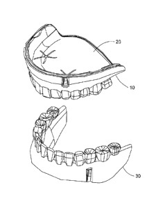
[0013] Fig. 1 is a perspective view of an embodiment of a removable
denture of the
present invention;
[0014] Fig. 2 is an exploded view of the removable denture of Fig. 1;
[0015] Fig. 3 is an exploded view of the removable denture of Fig. 1
viewed in another
view angle;
[0016] Fig. 3A is an enlarged view of an one-way venting valve of a
denture body of
the removable denture of Fig. 1;
[0017] Fig. 3B is a cross section of the one-way venting valve of Fig. 3A
along a line
3B-3B;
[0018] Fig. 4 is a top view of a first supporting base of the removable
denture of Fig. 1;
[0019] Fig. 5 is a perspective view of a first supporting base of the
removable denture
of Fig. 1;
[0020] Fig. 6 is a partially enlarged view of the first supporting base of
Fig. 4;
[0021] Fig. 7 is a cross section of the first supporting base of Fig. 6
along a line 7-7;
[0022] Fig. 8 is a cross section of the assembled removable denture of
Fig. 1;
[0023] Fig. 9 depicts the assembled removable denture of Fig. 1 used in an
oral cavity;
and
[0024] Figs. 10A and 10B depict another embodiment of a first supporting
base and a
second supporting base of a removable denture of the present invention.
DETAILED DESCRIPTION OF THE INVENTION
[0025] The following description is of the best-contemplated mode of
carrying out the
invention. This description is made for the purpose of illustrating the
general principles of
CA 3019723 2018-10-03
the invention and should not be taken in a limiting sense. The scope of the
invention is best
determined by reference to the appended claims.
[0026] Referring to Figs. 1, 2 and 3, a removable denture of the invention
includes an
upper jaw denture body 10, a first supporting base 20, a lower jaw denture
body 30 and a
second supporting base 40. The removable denture of the invention can be worn
on a
residual ridge of alveolus in an oral cavity. The residual ridge of alveolus
has mucosa on
which the removable denture of the invention can be attached to. The removable
denture of
the invention includes dentures for the upper jaw and for the lower jaw, and
is suitable for
patients of edentulous disease. The upper jaw denture body 10 and the first
supporting base
20 are adapted to be worn on the residual ridge of alveolus on an upper jaw,
and the lower
jaw denture body 30 and the second supporting base 40 are adapted to be worn
on the
residual ridge of alveolus on a lower jaw. The upper jaw denture body 10 has a
structure
similar to the lower jaw denture body 30, and the first supporting base 20 has
a structure
similar to the second supporting base 40. The size and appearance of the upper
jaw denture
body 10, the first supporting base 20, the lower jaw denture body 30 and the
second
supporting base 40 can be modified for different patients, depending on their
oral cavity
configuration. In this embodiment, the removable denture of the present
invention can be
applied only to the upper jaw or only to the lower jaw.
[0027] The upper jaw denture body 10 includes a mucosa-faced surface 11, a
groove
12, a notch 13 and denture teeth 14. In addition, the upper jaw denture body
10 further
includes an alveolus-mounted base 15 which is formed by artificially modeling.
The
mucosa-faced surface 11 is formed on an inner side of the alveolus-mounted
base 15.
When the removable denture is manufacturing, the first supporting base 20 is
formed firstly.
A first contact surface 21 of the first supporting base 20 is used to form a
working mold
through dental impression technique. Afterwards, the upper jaw denture body 10
is formed
by the working mold so that an inner surface of the upper jaw denture body 10
may serve as
a negative mold mating the first contact surface 21 of the first supporting
base 20. A
portion of the negative mold corresponding to a first supporting base flexible
cover 241 and
a notch 242 can be further ground or cut about 0.5 mm to facilitate air flow.
Thus, the
6
CA 3019723 2018-10-03
mucosa-faced surface 11 is formed. The mucosa-faced surface 11 is further
processed to
have a rough edge 111 having a width of about 2 mm to 10 mm so that an edge of
a flexible
pad 24 of the first supporting base 20 on the first contact surface 21 side is
maintained in a
condition that is ready to be detached from the rough edge 111 of the mucosa-
faced surface
11 of the upper jaw denture body 10 at any time, when the oral cavity is in a
chewing
condition, and another edge of the flexible pad 24 on the second contact
surface 22 side is
attached to the mucosa on the residual ridge of the alveolus and moved along
with the
mucosa to prevent air from entering into a gap that is formed between the
removable
denture and the mucosa. Similarly, the mucosa-faced surface 31 is further
processed to
have a rough edge 311 having a width of about 2 mm to 10 mm so that an edge of
a flexible
pad 44 of the second supporting base 40 on the first contact surface 41 side
is maintained in
a condition that is ready to be detached from the rough edge 311 of the mucosa-
faced
surface 31 of the lower jaw denture body 30 at any time, when the oral cavity
is in a
chewing condition and another edge of the flexible pad 44 on the second
contact surface 42
side is attached to the mucosa on the residual ridge of the alveolus and moved
along with
the mucosa to prevent air from entering into a gap that is formed between the
removable
denture and the mucosa. The groove 12 is formed on the mucosa-faced surface
11. The
notch 13 is formed on the alveolus-mounted base 15 and extends from the mucosa-
faced
surface 11 to the other side of the alveolus-mounted base 15. The denture
tooth 14 is fixed
to the alveolus-mounted base 15. The removable denture is worn in the oral
cavity for a
patent to chew, speak or other oral exercise. Except the aforementioned
structure, the upper
jaw denture body 10 has an appearance and a shape similar to a conventional
full-mouth
removable denture, but the portion corresponding to palatine bone has a
horseshoe shape
for holding the first supporting base 20.
[0028]
Referring to Figs. 2, 3, 3A and 3B, the upper jaw denture body 10 includes two
one-way venting valves. Each one-way venting valve includes a valve seat 16, a
venting
hole 161 and a denture body flexible cover 162. The venting hole 161 and the
denture body
flexible cover 162 are disposed on the valve seat 16. The amount and position
of the
denture body flexible cover 162 depend on the venting hole 161. The venting
hole 161 is at
7
CA 3019723 2018-10-03
a center of the one-way venting valve 16. The valve seat 16 surrounds the one-
way venting
hole 161. A portion of the valve seat 16 surrounding the venting hole 161
forms a concave
spherical surface, and the venting hole 161 is formed at the center of the
concave spherical
surface. The valve seat 16 further includes one or more notches 163 adjacent
to the denture
body flexible cover 162. The venting hole 161 is opened in viewing in a
direction
perpendicular to the mucosa-faced surface as shown in Fig. 2. As shown in Fig.
3, the
denture body flexible cover 162 detachably covers the venting hole 161 and
seals the
venting hole 161 in a normal condition so that the venting hole 161 and the
denture body
flexible cover 162 serve as an one-way venting valve. When air pressure on the
mucosa-
faced surface 11 of the alveolus-mounted base 15 is greater than air pressure
on the
occlusion surface, a pressure difference between the mucosa-faced surface 11
and the
occlusion surface opens the denture body flexible cover 162 so that air flows
from the
mucosa-faced surface 11 and through the venting hole 161 to push the denture
body
flexible cover 162 open and then flows to the occlusion surface through the
notch 163.
[0029] The
first supporting base 20 includes a first contact surface 21 and a second
contact surface 22 opposite to the first contact surface 21. The first contact
surface 21 and
the second contact surface 22 are arranged along an occlusion direction y and
located on an
outer side and an inner side of the first supporting base 20. The second
contact surface 22
is adapted to attach to mucosa on residual ridge of alveolus and palatine
bones such as
mucosa on upper jaw. The first contact surface 21 is detachably attached to
the upper jaw
denture body 10. As shown in Figs. 3 and 4, the first supporting base 20
includes a central
base 23 and a flexible pad 24 configured to attach to the mucosa on residual
ridge of
alveolus and palatine bones. A central portion of the flexible pad 24
surrounds the central
base 23. In viewing along the occlusion direction y, the flexible pad 24
encloses a
periphery of the central base 23 so that the first supporting base 20 includes
a central region
including the central base 23 and the central portion of the flexible pad 24
and a periphery
region including the flexible pad 24 only. That is
the periphery region of the first
supporting base 20 contains the flexible pad 24 only. The flexible pad 24 is
made of a film
formed by a chemical material with softness such as a soft resin, a silicon
gel and the like.
8
CA 3019723 2018-10-03
Therefore, flexibility of the periphery region is greater than flexibility of
the central region.
When the second contact surface 22 is attached to the mucosa in the oral
cavity, the
periphery region follows the movement of the movable mucosa to maintain the
tight
adhesion of the removable denture on the mucosa and ensure the gas tightness
between the
second contact surface 22 and the mucosa when the oral cavity is chewing. In
this
embodiment, the first supporting base 20 can be made of a single chemical
material such as
a silicon gel, a plastic or a rubber and the like. However, the chemical
material forms
greater hardness in the central region than in the periphery region. In
another embodiment,
the first supporting base 20 is made of chemical material of different
hardness such as
plastic, which provides similar effect to the previous embodiment. Referring
to Figs. 4 and
5, the flexible pad 24 encloses the central base 23 on the second contact
surface 22 so that
when the second contact surface 22 is attached to the mucosa, the central base
23 is
prevented from contact the mucosa directly, which causes uncomfortable
feelings of patient.
The flexible pad 24 encloses a bottom of the central base 23 on the second
contact surface
22 so that the central base 23 is hidden in the flexible pad 24 and not reveal
from the second
contact surface 22. In another embodiment, a portion of the central base 23 is
allowed to be
not enclosed by the flexible pad 24 as long as the gas tightness between the
second contact
surface 22 and the mucosa is maintained. Referring to Figs. 2 and 3, the
flexible pad 24
encloses at least the periphery of the central base 23 on the first contact
surface 21 to form
the first contact surface 21 which is the outer surface of the first
supporting base 20. In
another embodiment, the central base 23 of the first supporting base 20 is
permanently
joined to the upper jaw denture body 10, but the periphery region must be
detachably
attached.
[0030] The
central base 23 includes one or more connectors 231 and one or more
detaching buttons 232. In this embodiment, the central base 23 is made of a
non-metal
material (such as a silicon gel, resin or rubber having higher hardness). In
another
embodiment, the central base 23 is made of metal with flexibility often used
in dental
technique (such as titanium alloy, cobalt chromium alloy and the like) which
is able to
support the flexible pad 24. Referring to Figs. 4 to 7, the central base 23
includes two one-
9
CA 3019723 2018-10-03
way venting valves. Each one-way venting valve includes a venting hole 234
formed at the
center of the one-way venting valve and a valve seat 233 surrounding the
venting hole 234.
The venting hole 234 is not completely covered by the flexible pad 24 as shown
in Fig. 7.
The flexible pad 24 does not cover the venting hole 234 on the second contact
surface 22
side, and a concave spherical surface is formed on the first contact surface
21 of the central
base 23. The venting hole 234 is formed at the center of the concave spherical
surface.
The flexible pad 24 includes one or more first supporting base flexible covers
241 on the
first contact surface 21 side. The amount of the first supporting base
flexible cover 241
corresponds to the amount of the venting hole 234. The first supporting base
flexible cover
241 is configured to detachably cover the venting hole 234 on the first
contact surface 21
and maintain the venting hole 234 in a sealed condition. The valve seat 233
includes one or
more notches 242 adjacent to the first supporting base flexible cover 241. The
notch 242
enables the first supporting base flexible cover 241 to detach from the
venting hole 234
when the first supporting base flexible cover 241 is driven by air pressure
supporting the
venting hole 234, whereby the first supporting base flexible cover 241 and the
venting hole
234 serve as an one-way venting valve. When air pressure on the second contact
surface 22
is greater than air pressure on the first contact surface 21, a pressure
difference between the
second contact surface 22 and the first contact surface 21 opens the first
supporting base
flexible cover 241 so that air flows from the second contact surface 22 and
through the
venting hole 234 to push the first supporting base flexible cover 241 open and
then flows to
the first contact surface 21 through the notch 242. Afterwards, the air flows
through the
venting hole 161 to push the denture body flexible cover 162 open and then
flows out of the
removable denture through the notch 163. In another embodiment, depending upon
requirements, it is possible to form only one venting hole 161 and only one
venting hole
234.
[0031]
Referring to Figs. 2 and 3, in this embodiment, the central base 23 on the
upper
jaw is formed to match the contour of the residual ridge, the tongue and the
palatine bone.
When the central base is applied to the lower jaw, the central base is formed
to match the
contour of residual ridge, the cheek and the tongue. The connectors 231 are
arranged and
CA 3019723 2018-10-03
fixed to the central base 23 to correspond to the top of the alveolus. The
connector 231 has
a shape of frustum which can be cone frustum or a pyramid frustum or
combination of them.
The taper of the frustum is designed to range from 1 to 6' according to the
dental bi-layer
crown technique. The larger is the oral cavity, the frustum is designed to
have a larger area,
and the taper is also larger. The connector 231 is not enclosed by the
flexible pad 24 and
revealed from the first contact surface 21. When the first contact surface 21
is joined to the
upper jaw denture body 10, the connector 231 engages with the groove 12 of the
upper jaw
denture body 10, whereby the upper jaw denture body 10 is positioned to the
first
supporting base 20. The detaching button 232 has a maximal thickness of 5 mm
and fixed
to the central base 23. The position of the detaching button 232 corresponds
to a patient's
oral cavity. For example, the detaching button 232 may corresponds to
premolar. The
detaching button 232 extends toward patient's cheek, and the detaching button
232
protrudes from the upper jaw denture body 10 through the notch 13 when the
upper jaw
denture body 10 is joined to the first supporting base 20. When the patient
intends to
remove the denture, he/she pushes the detaching button 232 and pulls the upper
jaw denture
body 10 to separate the upper jaw denture body 10 from the first supporting
base 20.
[0032]
Referring to Figs. 2 and 5, the flexible pad 24 has a thickness of about 0.1
mm-
2 mm and has a periphery similar to a conventional full-mouth removable
denture. As
shown in Figs. 8 and 9, The central region of the flexible pad 24 is attached
to the central
base 23 and the rear edge of the flexible pad 24 extends to 1/3 an upper jaw
soft tissue 91
behind the upper jaw. The flexible pad 24 includes several venting passages
243 shaped as
a thin slot depressed from the second contact surface 22. The venting passages
243 are
formed on the second contact surface 22 and extend to the venting hole 234.
The venting
passages 243 communicate with the venting hole 234. The venting passages 243
are slots
extending in arbitrary directions or extending as branches. The venting
passages 243 are
formed by coating a thin layer of wax or other flushable material on an oral
cavity mold of
a patient which is obtained by dental impression technique (a preset space is
reserved
between two interfaces to prevent the interfaces contact directly). The
coating has
thickness and width of 0.1 mm-0.5 mm. A working mold is made through the
dental
11
CA 3019723 2018-10-03
impression technique. Several slots of 0.1 mm-0.5 mm are formed on the second
contact
surface 22 of the flexible pad 24 when the first supporting base 20 is formed
by the working
mold. The slots are the venting passages 243.
[0033] Referring Figs 1 to 3, when a patient wears the removable denture
of the present
invention, he/she puts the first supporting base 20 into his/her oral cavity.
The second
contact surface 22 of the first supporting base 20 is attached to mucosa of
the patient when
the first contact surface 21 is pressed by the patient. The first supporting
base 20 is stably
attached to the mucosa by the adhesion force of saliva and the periphery
region of the first
supporting base 20. When the first contact surface 21 is slightly pressed by
the patient, air
between the second contact surface 22 and the mucosa and in the venting
passages 243 are
pressed, and thus the air pressure therein rises. When the air pressure on the
second contact
surface 22 is higher than the air pressure on the first contact surface 21,
air flows through
the venting passages 243 and the venting hole 243 to push the supporting base
flexible
cover 241 open, and then the air flows to the first contact surface 12 through
the notch 242.
When the patient release the first supporting base 20, since the air between
the second
contact surface 22 and the mucosa is purged, the second contact surface 22 has
been tightly
attached to the mucosa or in a negative pressure status (relative to vacuum)
and the venting
passages 243 is in a negative pressure status (relative to vacuum), the first
supporting base
20 is maintained to be attached to the mucosa of his/her oral cavity. When the
first
supporting base 20 is positioned in the oral cavity, the upper jaw denture
body 10 can be
joined to the first supporting base 20. When the upper jaw denture body 10 is
joined to the
first supporting base 20, the mucosa-faced surface 11 contacts the first
contact surface 21.
The patient may further slightly press the upper jaw denture body 10 so as to
press the first
supporting base 20 again.
[0034] After the removable denture has been worn into the patient's oral
cavity, the
upper jaw denture body 10 and the first supporting base 20 are pressed when
the patient is
chewing. If air or saliva enters between the second contact surface 22 and the
mucosa, the
air or saliva can be purged to a space between the upper jaw denture body 10
and the first
supporting base 20 through the venting passages 234, and then purged out of
the upper jaw
12
CA 3019723 2018-10-03
denture body 10 through the venting hole 161, whereby the negative pressure
status is
maintained between the second contact surface 22 and the mucosa, and the first
supporting
base 20 is stably attached to the mucosa without sliding or even falling off.
Since the
mucosa-faced surface 11 has a rough edge 111, the periphery of the mucosa-
faced surface
11 is ready to be detached from the periphery of the flexible pad 24 at any
time, but the
periphery of the flexible pad 24 is maintained to be tightly attached to the
mucosa. When
the patient is chewing, the periphery of the flexible pad 24 moves along with
the movable
mucosa but air is prevented from entering the first supporting base 20 and the
mucosa,
which contributes the adhesion of the first supporting base 20 to the mucosa.
[0035]
Referring to Figs. 1 to 3, the structure of the lower jaw denture body 30 is
similar to the structure of the upper jaw denture body 10. The lower jaw
denture body 30
includes a mucosa-faced surface 31, a groove 32, a notch 33 and denture teeth
34. The
lower jaw denture body 30 further includes a alveolus-mounted base. The mucosa-
faced
surface 31 has a rough edge 311. The second supporting base 40 has a structure
similar to
the structure of the first supporting base 20. The second supporting base 40
includes a first
contact surface 41, a second contact surface 42, a central base 43 and a
flexible pad 44.
The central base 43 includes connectors 431 and a detaching button 432. The
mucosa-
faced surface 31 of the lower jaw denture body 30 is formed through the dental
impression
technique as the mucosa-faced surface 11 of the upper jaw denture body 10. A
working
mold is made by the first contact surface 41 of the second supporting base 40
through
dental impression technique. The lower jaw denture body 30 is formed by the
working
mold. The inner surface of the lower jaw denture body 30 serves as a cavity
mold for the
first contact surface 41 of the second supporting base 40. The inner surface
of the lower
jaw denture body 30 is the mucosa-faced surface 31 of the lower jaw denture
body 30. The
flexible pad 44 includes several venting passages 443 which are exemplarily
narrow slots.
The flexible pad 44 encloses the periphery of the central base 43. The
difference between
the upper jaw denture body 10 and the lower jaw denture body 30 is that the
upper jaw
denture body 10 and the first supporting base 20 are worn on the upper jaw,
whereas the
lower jaw denture body 30 and the second supporting base 40 are worn on the
lower jaw.
13
CA 3019723 2018-10-03
The venting passages 433 of the flexible pad 44 has the same effects and
functions as the
venting passages 234 of the flexible pad 24, and the description of the
venting passages 433
is thus neglected.
[0036] Since the one-way venting valve structure generates the highly
negative
pressure effects, when the patient intends to remove the denture, the upper
jaw denture
body 10 and the lower jaw denture body 30 are easily removed from the first
supporting
base 20 and the second supporting base 40 through the detaching buttons 232
and 432
respectively. However, the first supporting base 20 and the second supporting
base 40 are
still tightly attached to mucosa on the upper jaw and the lower jaw due to the
negative
pressure effects. To avoid injuring the patient, the venting passages 243 and
443 are
designed to have one or two venting passages 243 and 443 extending from tongue
side to
cheek side, but the central base 23 and 43 extends not yet to cheek side. The
patient merely
needs to rub the portion of the flexible pads 24 and 44 where the venting
passages 243 and
443 extending from tongue side to cheek side is formed so that air is allowed
to enter the
venting passages 243 and 443 and thus reduce the negative pressure effects,
whereby the
first supporting base 20 and the second supporting base 40 can be easily
removed.
[0037] Referring to Figs. 10A and 10B, for some patients who need the
negative
pressure effects to be enhanced, for example the patient's alveolus bone is
seriously shrunk,
an active concave surface is formed around the venting hole 234 on the second
surface 22
of the first supporting base 20 or around the venting hole 433 on the second
surface 42 of
the second supporting base 40. The venting passages 243 and 443 extend from
the active
concave surface in all directions to enhance the negative pressure effect.
However, it is
noticed that the venting passages 243 and 443 are not allowed to approach the
boundary of
the second contact surface 22 and 42. When the patient is chewing, the upper
jaw denture
body 10 presses the first supporting base 20 through a biting force or other
forces to enable
the first supporting 20 to attach to the mucosa more tightly. At this time,
air between the
flexible pads 24, 44 and the mucosa is squeezed out through the venting holes
234 and 433.
When the biting force disappears, air is not sucked to reverse back due to the
one-way
venting valve structure. As the flexible pads 24 and 44 and the mucosa are
flexible, the
14
CA 3019723 2018-10-03
active concave surface 244 restores its original space. At this time, the
concave surface 244
serves as a negative pressure chamber where a vacuum-negative pressure status
(relative
vacuum) is formed. The thickness of the active concave surface 244 must be
designed in a
range of 0.1 mm to 0.5 mm. Accordingly, in the second embodiment, it is
required to tell
the patient firstly that the mucosa under the surface of the notch may cause a
hyperplasia
and it is preferred to have an approval from the patient prior to manufacture
of a removable
denture. The existence of the active concave surface 244 will stimulate the
mucosa to grow
up therein. However, when the thickness of the active concave surface 244 is
designed in a
narrow range, the active concave surface 244 is completely attached to the
mucosa when
the biting force exerts. The growing of mucosa can be controlled in a very
small area.
[0038] The removable denture of the present invention provides a greater
flexibility of
the periphery region of the supporting base, which enables the supporting base
to move
along with the mucosa and attach the mucosa when the patient is chewing. This
contributes
to the high gas tightness between the supporting base and the mucosa and
improves the
positioning stability of the removable denture in the oral cavity.
[0039] Since the supporting base includes the central base and the
flexible pad, and the
central region has a lower flexibility (more rigid) than the periphery region,
the central base
or the more rigid central region maintains and supports the whole structure of
the
supporting base so as to prevent the flexible pad or the more flexible
periphery region from
folding or wrinkling which may reduce the gas tightness between the supporting
base and
the mucosa. This contributes to the high gas tightness between the supporting
base and the
mucosa and improves the positioning stability of the removable denture in the
oral cavity.
[0040] The venting passages are distributed in the second contact surface
of the
supporting base to provide the negative pressure effect for all portions of
the second contact
surface without causing deformation of the mucosa. Since the venting passage
is narrow
and shallow, the venting passages are pressed to tightly attach to the mucosa,
which
prevents the growing of the mucosa due to the negative pressure effect. In a
normal
condition, the growing of the mucosa is controlled in a very small area and is
almost non-
visible.
CA 3019723 2018-10-03
[0041] While
the invention has been described by way of example and in terms of
preferred embodiment, it is to be understood that the invention is not limited
thereto. To
the contrary, it is intended to cover various modifications and similar
arrangements (as
would be apparent to those skilled in the art). Therefore, the scope of the
appended claims
should be accorded the broadest interpretation so as to encompass all such
modifications
and similar arrangements.
16
CA 3019723 2018-10-03