Note: Descriptions are shown in the official language in which they were submitted.
WATER SOURCE HEAT PUMP HEAD PRESSURE CONTROL
FOR HOT GAS REHEAT
CROSS-REFERENCE TO RELATED APPLICATIONS
[0001] This application claims the benefit of U.S. Provisional
Application No.
62/568,963, filed October 6, 2017.
BACKGROUND
Field of the Invention
[0002] The present invention generally relates to a refrigerant system.
More
specifically, the present invention relates to a heat pump with head pressure
control for
hot gas reheat.
Background Information
[0003] Refrigerant systems are utilized to control the temperature and
humidity of
air in various indoor environments to be conditioned.
[0004] A heat pump is a refrigerant system that is typically operable
in both cooling
and heating modes. While air conditioners are familiar examples of heat pumps,
the term
"heat pump" is more general and applies to many HVAC (heating, ventilating,
and air
conditioning) devices used for space heating or space cooling. When a heat
pump is used
for heating, it employs the same basic refrigeration-type cycle used by an air
conditioner
or a refrigerator, but in the opposite direction, releasing heat into the
conditioned space
rather than the surrounding environment. In this use, heat pumps generally
draw heat
from cooler external air, water or from the ground.
[0005] In a cooling mode, a heat pump operates like a typical air
conditioner, i.e., a
refrigerant is compressed in a compressor and delivered to a condenser (or an
outdoor
heat exchanger). In the condenser, heat is exchanged between a medium such as
outside
air, water or the like and the refrigerant. From the condenser, the
refrigerant passes to an
expansion device, at which the refrigerant is expanded to a lower pressure and
temperature, and then to an evaporator (or an indoor heat exchanger). In the
evaporator,
heat is exchanged between the refrigerant and the indoor air, to condition the
indoor air.
When the refrigerant system is operating, the evaporator cools the air that is
being
- 1 -
Date regunE3r-eiceived 2023-02-10
supplied to the indoor environment. In addition, as the temperature of the
indoor air is
lowered, moisture usually is also taken out of the air. In this manner, the
humidity level of
the indoor air can also be controlled.
[0006] Reversible heat pumps work in either direction to provide heating
or cooling to
the internal space as mentioned above. Reversible heat pumps employ a
reversing valve to
reverse the flow of refrigerant from the compressor through the condenser and
evaporation
coils. In heating mode, the outdoor coil is an evaporator, while the indoor
coil is a
condenser. The refrigerant flowing from the evaporator (outdoor coil) carries
the thermal
energy from outside air (or soil) indoors. Vapor temperature is augmented
within the
pump by compressing it. The indoor coil then transfers thermal energy
(including energy
from the compression) to the indoor air, which is then moved around the inside
of the
building by an air handler.
100071 Alternatively, thermal energy can be transferred to water, which
is then used to
heat the building via radiators or underfloor heating. The heated water may
also be used
for domestic hot water consumption. The refrigerant is then allowed to expand,
cool, and
absorb heat from the outdoor temperature in the outside evaporator, and the
cycle repeats.
This is a standard refrigeration cycle, save that the "cold" side of the
refrigerator (the
evaporator coil) is positioned so it is outdoors where the environment is
colder.
10008] In addition, instead of an air source heat pump, water source heat
pumps can
also be provided in which the outdoor unit exchanges heat with a water source,
and the
indoor unit exchanges heat with air. In cooling mode the cycle is similar, but
the outdoor
coil is now the condenser and the indoor coil (which reaches a lower
temperature) is the
evaporator. This is the familiar mode in which air conditioners operate. If a
water coil is
used for the so-called outdoor heat exchanger, it is not necessary for the
water coil to be
outside.
[0009] U.S. Patent Nos. 7,275,384 and 7,287,394 disclose prior art heat
pumps with
reheat circuits.
- 2 -
CA 3019759 2018-10-04
SUMMARY
100101 This invention relates to a heat pump system that is operable in
both cooling
and heating modes, and which utilizes a hot gas reheat coil operable in a hot
gas reheat
mode.
[0011] While reheat coils have been incorporated into the air source air
conditioning
systems operating in the cooling mode, they have not been utilized in water
source heat
pump systems as disclosed herein.
[0012] One illustrative embodiment utilizes a pressure switch located on
compressor
discharge line, a two way water valve located at the inlet of the coax coil
and a relay to
control the afore mentioned water valve. The purpose of this switch is to
control the
operation of a water valve either allowing water flow or stopping water flow
to the coax
coil depending on the compressor discharge pressure switch settings. The
pressure switch
is allowed to energize or deenergize the two way valve maintaining the
discharge pressure
(saturated discharge temperature) over an operating window. Maintaining an
adequate
discharge pressure allows proper operation of the TEV and proper flow of
refrigerant to
the evaporator preventing the evaporator coil from dropping below the freezing
point of
water at the surface of the coil. Without the arrangement inherent safeties in
the control
system of the water source heat pump could shut the unit down. The switch also
ensures
that discharge pressure does not elevate above the maximum operating pressure
allowed.
The configuration is set up to not be employed when the unit is in straight
cooling mode or
in heating mode. Allowing operation during either of these modes would inhibit
the
operating efficiency of the water source heat pump.
[0013] The system can be configured to utilize a normally open or
normally closed
two way valve depending on the customer's needs.
[0014] This invention can improve the overall operating window of hot gas
reheat
operation improving compressor reliability by reducing compressor cycling and
avoiding
nuisance trips as a result of coil freeze ups thereby reducing overall
warranty claims. This
system would also be a suitable response to units which offer hybrid systems
to address
similar applications.
- 3 -
CA 3019759 2018-10-04
100151 One or more of the foregoing objects can basically be attained by
providing an
air conditioning system and/or method in accordance with any one or more of
the aspects
below, and/or any of the features discussed below and/or illustrated in the
attached
drawings.
[0016] A heat pump system in accordance with a first aspect includes a
compressor, a
usage side heat exchanger, a heat source side heat exchanger arranged to
exchange heat
between a heat transfer medium and refrigerant flowing therethrough, an
expansion
mechanism, a main refrigerant flow control device switchable between a cooling
mode
and a heating mode, a gas reheat heat exchanger connected in the refrigerant
circuit, a fan
disposed to direct an airflow across the usage side heat exchanger and the gas
reheat heat
exchanger into a target space, and a secondary refrigerant flow control device
switchable
between a first mode and a second mode. The compressor delivers compressed
refrigerant
to a discharge line and receiving a refrigerant from a suction line. In the
cooling mode,
refrigerant flows from the discharge line through a refrigerant circuit, to
the heat source
side heat exchanger, to the expansion mechanism and then to the usage side
heat
exchanger. In the heating mode, refrigerant flows from the discharge line
through the
refrigerant circuit to the usage side heat exchanger, to the expansion device
and then to the
heat source side heat exchanger. In the first mode, refrigerant flows from the
discharge
line to the main refrigerant flow control device in the heating mode and the
cooling mode.
In the second mode, refrigerant flows from the discharge line to the gas
reheat heat
exchanger in a gas reheat mode and then flows to the main refrigerant flow
control device.
A flow of the heat transfer medium to the heat source side heat exchanger is
adjustable.
[0017] A heat pump in accordance with a second aspect is the heat pump of
the first
aspect, in which the heat transfer medium of the heat source side heat
exchanger is a
liquid.
[0018] A heat pump in accordance with a third aspect is the heat pump of
the second
aspect, in which the heat transfer medium of the source side heat exchanger is
water.
[0019] A heat pump in accordance with a fourth aspect is the heat pump of
the second
or third aspects, in which the source side heat exchanger is a coaxial heat
exchanger.
- 4 -
CA 3019759 2018-10-04
[0020] A heat pump in accordance with a fifth aspect is the heat pump of
any of the
second to fourth aspects, further including a heat transfer medium flow
control device
disposed on an inlet side of the heat source side heat exchanger to adjust
flow of the heat
transfer medium into the heat source side heat exchanger.
[0021] A heat pump in accordance with a sixth aspect is the heat pump of
the fifth
aspect, in which the heat transfer medium flow control device includes a flow
control
valve.
[0022] A heat pump in accordance with a seventh aspect is the heat pump
of the fifth
or sixth aspects, in which the heat transfer medium flow control device
permits flow of the
heat transfer medium to flow to the heat source side heat exchanger when the
secondary
refrigerant flow control device is in the first mode in the heating mode and
the cooling
mode, and the heat transfer medium flow control device is configured to adjust
flow of the
heat transfer medium to the heat source side heat exchanger when the secondary
refrigerant flow control device is in the second mode in the gas reheat mode.
[0023] A heat pump in accordance with an eighth aspect is the heat pump
of any of the
fifth to seventh aspects, further including a control element disposed between
a discharge
port of the compressor and an inlet of the gas reheat heat exchanger, the
control element
being configured to control the heat transfer medium flow control device.
[0024] A heat pump in accordance with a ninth aspect is the heat pump of
the eighth
aspect, in which the control element includes a switch, the switch being
connected in a
control circuit to the heat transfer medium flow control device.
[0025] A heat pump in accordance with a tenth aspect is the heat pump of
the ninth
aspect, in which the control circuit includes a relay that receives a wired or
wireless signal
from a thermostat to open or close the relay.
[0026] A heat pump in accordance with an eleventh aspect is the heat pump
of the
ninth or tenth aspects, in which the switch includes a pressure control switch
that is
normally open unless a pressure of refrigerant at the control element falls
below an
actuation pressure.
[0027] A heat pump in accordance with a twelfth aspect is the heat pump
of the
eleventh aspect, in which once the pressure at the control element has fallen
below the
- 5 -
CA 3019759 2018-10-04
actuation pressure, the switch will be closed until the pressure at the
control element
rises above a release pressure that is higher than the actuation pressure.
[0028] A heat pump in accordance with a thirteenth aspect is the heat
pump of the
twelfth aspect, in which if the pressure control switch is in a normally open
position,
the pressure control switch will remain in the open position even when the
pressure at
the control element falls below the release pressure.
[0029] A heat pump in accordance with a fourteenth aspect is the heat
pump of any
of the first to thirteenth aspects, in which the secondary refrigerant flow
control device
is a three-way valve that selectively communicates refrigerant from the
refrigerant
circuit to the reheat coil.
[0030] A heat pump in accordance with a fifteenth aspect is the heat
pump of any
of the first to fourteenth aspects, in which the main refrigerant flow control
device is a
four-way valve.
[0031] A heat pump in accordance with a sixteenth aspect is the heat
pump of any of
the first to fifteenth aspects, in which the gas reheat heat exchanger is
positioned upstream
of the usage side heat exchanger in the gas reheat mode along the refrigerant
circuit
[0032] A heat pump in accordance with a seventeenth aspect is the heat
pump of
any of the first to sixteenth aspects, in which the gas reheat heat exchanger
is
positioned upstream of the main refrigerant flow control device in the gas
reheat mode
along the refrigerant circuit.
According to an aspect of the present invention there is provided A heat pump
system
comprising:
a compressor, the compressor delivering compressed refrigerant to a
discharge line and receiving a refrigerant from a suction line;
a usage side heat exchanger;
a heat source side heat exchanger arranged to exchange heat between a heat
transfer medium and refrigerant flowing therethrough;
an expansion valve;
a main refrigerant flow control valve switchable between a cooling mode in
which refrigerant flows from the discharge line through a refrigerant circuit,
to the
heat source side heat exchanger, to the expansion valve and then to the usage
side heat
exchanger, and
- 6 -
Date regunE3r-eiceived 2023-02-10
a heating mode in which refrigerant flows from the discharge line through
the refrigerant circuit to the usage side heat exchanger, to the expansion
valve and
then to the heat source side heat exchanger;
a gas reheat heat exchanger connected in the refrigerant circuit;
a fan disposed to direct an airflow across the usage side heat exchanger and
the gas reheat heat exchanger into a target space;
a secondary refrigerant flow control valve switchable between a first mode
in which refrigerant flows from the discharge line to the main refrigerant
flow control
valve in the heating mode and the cooling mode, and
a second mode in which refrigerant flows from the discharge line to the gas
reheat heat exchanger in a gas reheat mode and then flows to the main
refrigerant flow
control valve; and
a heat transfer medium flow control valve disposed on an inlet side of the
heat source side heat exchanger to adjust flow of the heat transfer medium
into the
heat source side heat exchanger;
the heat transfer medium flow control valve permitting flow of the heat
transfer medium to flow to the heat source side heat exchanger when the
secondary
refrigerant flow control valve is in the first mode in the heating mode and
the cooling
mode, and
the heat transfer medium flow control valve being configured to adjust flow
of the heat transfer medium to the heat source side heat exchanger when the
secondary
refrigerant flow control valve is in the second mode in the gas reheat mode.
[0033] These and other objects, features, aspects and advantages of the
present
invention will become apparent to those skilled in the art from the following
detailed
description, which, taken in conjunction with the annexed drawings, discloses
preferred embodiments.
BRIEF DESCRIPTION OF THE DRAWINGS
[0034] Referring now to the attached drawings which form a part of this
original disclosure:
[0035] Figure 1 illustrates a conventional water source refrigerant
heat
pump schematic, in a cooling mode;
[0036] Figure 2 illustrates the heat pump schematic of Figure 1, in a
heating mode;
- 6a -
Date reguaMel3r-eiceived 2023-02-10
[0037] Figure 3 illustrates the heat pump schematic of Figures 1-2, but
in a hot gas
reheat mode;
[0038] Figure 4 illustrates the heat pump schematic of Figure 3, in a hot
gas reheat
mode and with system parts identified for convenience;
[0039] Figure 5 illustrates an embodiment of a water source refrigerant
heat pump
schematic, which is a modification of the schematic of Figures 1-4, in a hot
gas reheat
mode and with system parts identified for convenience like Figure 4, but also
illustrating
the head pressure control switch (HPCS) and water valve (WV) in accordance
with the
embodiment;
[0040] Figure 6 is a schematic view of the heat pump illustrated in
Figure 5, in the
cooling mode with the switch open and the relay open;
[0041] Figure 7 is a schematic view of the heat pump illustrated in
Figures 5-6, in the
heating mode with the switch open and the relay open;
[0042] Figure 8 is a schematic view of the heat pump illustrated in
Figures 5-7, in the
hot gas reheat mode with the switch opened and the relay closed so that the
water valve
allows the flow of water but is capable of prohibiting water flow to the water
coil;
[0043] Figure 9 is a schematic view of a water valve control circuit in a
heating or
cooling mode with the switch open, and so the thermostat keeps the relay open
so that the
water valve is open;
[0044] Figure 10 is a schematic view of the water valve control circuit
of Figure 9, but
in the hot gas reheat mode with the relay closed so that the water valve being
open or
closed is determined by the switch, which is shown open in this Figure so that
the water
valve is open;
[0045] Figure 11 is a schematic view of water valve control circuit of
Figure 10 in the
hot gas reheat mode with the relay closed so that the water valve being open
or closed is
determined by the switch, with the switch open in response to the pressure at
the switch
being above an actuation pressure (e.g., 240 psi) so that the water valve is
open;
[0046] Figure 12 is a schematic view of water valve control circuit of
Figure 10 in the
hot gas reheat mode with the relay closed so that the water valve being open
or closed is
determined by the switch, with the switch closed in response to the pressure
at the switch
- 7 -
CA 3019759 2018-10-04
being below the actuation pressure (e.g.. 240 psi) so that the water valve is
closed (this
can occur in the state shown in Figure 8);
[0047] Figure 13 is a schematic view of water valve control circuit of
Figures 10-12
in the hot gas reheat mode with the relay closed so that the water valve being
open or
closed is determined by the switch, with the switch being opened in response
to the
pressure at the switch rising above a release pressure (e.g., 380 psi) that is
above the
actuation pressure so that the water valve is closed; and
[0048] Figure 14 is a schematic view of a MicroTech SmartSource unit
controller
and I/O expansion module connected to the water valve control circuit of
Figures 9-13
and illustrating one suitable thermostat.
DETAILED DESCRIPTION OF EMBODIMENT(S)
[0049] Selected embodiments will now be explained with reference to
the drawings. It
will be apparent to those skilled in the art from this disclosure that the
following
descriptions of the embodiments are provided for illustration only and not for
the purpose
of limiting the invention as defined by the appended claims and their
equivalents.
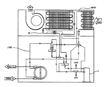
Figures 1 to 8 show COMPACT Vertical Refrigerant Schematics ¨ Hot Gas
Reheat in different modes as discussed below. Figure 1 shows cooling mode;
Figure 2
shows heating mode; Figure 3 shows hot gas reheat mode; Figure 4 shows hot gas
reheat
mode; Figure 5 shows hot gas reheat mode; Figure 6 shows cooling mode; Figure
7 shows
heating mode; and Figure 8 shows heating mode.
In the figures:
BCV refers to Hot Gas Bleed Check Valve
HCV refers to Hot Gas Check Valve
HEL refers to Heat Gas Reheat Valve Equalization Line
IBS refers to TXV Bulb Sensor
LPS refers to Low Pressure Switch
HBL refers to Hot Gas Bleed Line
Ill refers to TXV Pressure Equalization Line
UPS refers to High Pressure Switch
NF refers to no flow
WV refers to Water Valve (NO) Open Allowing Water Flow 0-volts
SO refer to Switch Open
- 8 -
Date regue3/?33ENceived 2023-02-10
[0050] Referring initially to Figures 1-4, a conventional water source
heat pump (1) is
illustrated. Figure 1 shows the cooling mode, Figure 2 shows the heating mode
and Figure
3 shows the hot gas reheat mode. Figure 4 also shows the hot gas reheat mode
just like
Figure 3 but further includes labels for the parts of system. These parts are
the same in
Figures 1-8, and thus, may not be included in all the Figures for the sake of
convenience.
[0051] In the cooling mode of Figure 1, compressed high pressure
refrigerant flow
(HPRF) exits the compressor (C) and flows through the hot gas reheat valve
(10) to the
reversing valve (12), through the water coil (16) to the thermostatic
expansion valve
(TEV). The TEV then reduces the pressure of the refrigerant. The resulting low
pressure
refrigerant flow (LPRF) then flows through a distributor (D) and then through
the DX
coil or the Evaporator (14), back through the reversing valve (12) and back to
the suction
side of the compressor (C). Note the refrigerant does not flow through the hot
gas reheat
coil (18) (note the "x" on the flow path at several locations).
[0052] In the heating mode of Figure 2, compressed high pressure
refrigerant flow
(HPRF) exits the compressor (C) and flows through the hot gas reheat valve
(10) to the
- 8a -
3
Date regueR33alLiceived 2023-02-10
reversing valve (12), through the DX coil or the Evaporator (14), and through
the
distributor (D) to the thermostatic expansion valve (TEV). The TEV then
reduces the
pressure of the refrigerant. The resulting low pressure refrigerant flow
(LPRF) then
flows through the water coil (16), back through the reversing valve (12) and
back to the
suction side of the compressor (C). Note the refrigerant does not flow through
the hot
gas reheat coil (18) (note the "x" on the flow path at several locations).
[0053] In the hot gas reheat mode shown in Figures 3-4, compressed
high pressure
refrigerant flow (HPRF) exits the compressor (C) and flows through the hot gas
reheat
valve (10) (the flow at the hot gas reheat valve (10) is switched as compared
to the cooling
and heating modes) to the hot gas reheat coil (18), through the hot gas reheat
coil (18),
through the hot gas check valve, through the reversing valve (12), and through
the water
coil (16) to the 1EV. The fEV then reduces the pressure of the refrigerant.
The resulting
low pressure refrigerant flow (LPRF) then flows through the distributor (D),
the DX coil or
Evaporator (14), back through the reversing valve (12) and back to the suction
side of the
compressor (C).
[0054] In Figures 1-4, the hot gas reheat valve (10) is a conventional
three-way
valve that sends refrigerant out of only one of the outlets as shown in the
Figures.
[0055] Referring now to Figures 5-14, an example of a heat pump (1')
in accordance
with the present invention will not be explained. Referring initially to
Figures 5-8, a
heat pump (1') is illustrated that is a modified version of the heat pump (1)
illustrated in
Figures 1-4. Specifically, the heat pump (1') illustrated in Figures 5-8
includes one
example of a structure that allows adjustment of the water flow to the water
coil (16)
during the hot gas reheat mode. Specifically, the heat pump (1') of Figures 5-
8 includes
a water valve (WV) disposed at an inlet of the water coil (16) and a head
pressure
control switch (HPCS) disposed between the outlet (0) of the compressor (C)
and the
hot gas reheat valve, as best shown in Figure 5.
[0056] The water valve (WV) and the head pressure control switch
(HPCS) are
connected in and form parts of a water valve control circuit, which is shown
in Figures 6-
14. Figures 5 and 8 illustrate a hot gas reheat mode of this embodiment.
In Figures 6 and 7, noting that RLO refers to Relay Open, the applicant
further notes that
Theimostat sends signal to relay (0-volts) keeping relay in Noonally open
position and
that in cooling mode, switch is not employed.
- 9 -
Date re guagel3reiceived 2023-02-10
In Figure 8, noting that RLC refers to Relay Closed, the applicant further
notes that
Thermostat sends signal to relay (24-volts) changing relay to closed position,
that the
switch can now open or close based on the switches actuation pressure and
release
pressure; and that in Hot Gas Reheat Mode, switch is employed.
In Figure 8, SA refers to switch being active and can open/close based on
actuation/released pressure specifications, which allows or stops water flow
based on
switch pressure specifications. This operation is different than the hot gas
reheat mode
operation of Figures 3-4. On the other hand,
- 9a -
Date re wage 3received 2023-02-10
Figures 6-7 illustrate cooling and heating modes of this embodiment,
respectively.
Despite the additional parts, i.e., the water valve (WV), the head pressure
control switch
(HPCS) and the other parts of the water valve control circuit, in the cooling
and heating
modes of Figures 6-7, the heat pump (1') of this embodiment operates the same
as cooling
and heating modes of Figures 1-2, respectively (note the "x" on the flow path
at several
locations). In Figures 6-8, the High Pressure Switch is removed, i.e., only
the head
pressure control switch (HPCS) is shown for the sake of illustration.
[0057] In this case, the water valve (WV) is a "normally open" valve, and
thus, unless
the relay and the head pressure control switch (HPCS) are both closed, the
water valve
(WV) will remain open so that water flows to the water coil (16). However, it
will be
apparent to those skilled in the art from this disclosure that the water valve
can be a
"normally closed" valve. In such a situation, the switch and the relay
operations as well as
the control signals could be reversed without departing from the scope of the
present
invention. In any case, the water valve (WV) is preferably controlled to be
open/closed as
explained below.
[0058] Referring to Figure 5, an operation in the hot gas reheat mode is
illustrated in
which the heat pump of this embodiment operates the same as the heat pump of
Figures 3-
4 in the hot gas reheat mode. However, in Figure 8 an operation in the hot gas
reheat
mode is illustrated in which the heat pump of this embodiment operates
differently than
the heat pump of Figures 3-4 in the hot gas reheat mode. Specifically, in
Figure 8, the
water valve can be closed so no water flows to the water coil (16). This
occurs when the
thermostat closes the relay as shown (because the heat pump is in the hot gas
reheat mode
¨ not in the cooling or heating mode), and the head pressure control switch
(HPCS) is
closed due to the pressure at the head pressure control switch (HPCS) being
below an
actuation pressure. See Figures 8 and 12. In other words, in Figure 8 the head
pressure
control switch (HPCS) can control whether the water valve (WV) is open or
closed based
on the logic shown in Figures 9-13.
[0059] Referring to Figure 9-13, the water valve control circuit will now
be explained
in more detail.
- 10 -
CA 3019759 2018-10-04
[0060] In Figures 9 and 10, SNO refers to "Switch Normally OPEN". In
Figure 9 the
heat pump is in a heating or cooling mode with the switch open. The thermostat
is keeping
the relay open so that the water valve is open so that regardless of the
position of the
switch, the control circuit is not closed and the water valve (WV) remains
open, i.e., the
water valve is a normally open valve in this embodiment. Regardless of the
pressure, if the
relay is open, such as in the heating or cooling mode, the water valve (WV)
will remain
open allowing the water to flow.
[0061] Noting that SW refers to Switch, in Figure 10 switch SW is now
active and can
respond to actuation/release pressure. The switch is normally OPEN. In Figures
10 to 13 10,
V24 refers to 24 volts when thermostat is in Hot Gas Mode. In Figure 10, ST1
indicates that
Switch is now active and now can respond to actuation/release pressure. In
Figure 10, the
relay is closed because the heat pump is in the hot gas reheat mode. Thus, the
switch is now
active to determine if the control circuit is closed. In Figure 10, the switch
is in the normally
open position and the water valve (WV) remains open, i.e., the water valve is
a normally
open valve in this embodiment.
[0062] In Figure 11, the Switch SW remains open until pressure falls
below 240psi;
Example - Release Pressure: 380pgig Actuation Pressure: 240 psig. In Figure
11, ST2
indicates that Switch remains open until pressure falls below 240 psi -
Example Release
Pressure: 380psig Actuation Pressure 240 psig. In Figure 11, an arrangement
similar to
Figure 10 is shown. In Figure 11, the pressure has been determined, and the
pressure is
above a release pressure (e.g., 240 psi). Therefore, the switch will remain
open so that
water continues to flow to the water coil (16). The control circuit will
remain in this mode
of operation unless the pressure drops below the actuation pressure.
[0063] In Figure 12, the Switch closes when pressure is below
actuation pressure and
Switch closes below 240 psi and remains closed until pressure increases above
380psi. In
Figure 12, ST3 indicates that Switch closes when pressure is below actuation
pressure;
WV1 indicates Water Valve CLOSED No Water Flowin 24-volts. In Figure 12, an
arrangement like Figure 11 is illustrated, but after the pressure has dropped
below the
actuation pressure (e.g., 240 psi). Once the pressure falls below the
actuation pressure in
the hot gas reheat mode, the switch will close. Note the relay is already
closed because In
the system is in the hot gas reheat mode. Therefore, once the switch is
closed, the control
circuit is closed and water flow to the water coil (16) is stopped by the
water valve (WV).
The system will then remain in this configuration until the pressure rises
above a release
- 11 -
Date re wage' 3received 2023-02-10
pressure (e.g., 380 psi) that is higher than the actuation pressure. In other
words, once the
pressure has fallen below the actuation pressure, the switch will remain
closed even if the
pressure rises about the actuation pressure.
[0064] In Figure 13, Above 800 psi, then valve opens allowing ater
flow and remains
open until pressure falls below 240psi. In Figure 13, ST4 indicates that
Switch Open and
that above 380psi, then valve opens allowing water flow and remains open until
pressure
falls below 240 psi; and WV2 indicates Water Valve OPEN Water Flowin. In
Figure 13, an
arrangement like Figure 12 is illustrated but illustrating a situation where
the pressure has
risen above the release pressure to reopen the switch. The relay is still
closed due to the
system being in the hot gas reheat mode. Therefore, again, the switch will
determine if the
control circuit is open or closed. The switch will now remain open unless the
pressure falls
below the actuation pressure, like Figures 11-12. As mentioned above, the
actuation pressure
is below the release pressure. Due to this
- lla -
wage' 3rei Date received 2023-02-10
configuration, it is possible for the switch to be open or closed at a common
pressure
between the actuation pressure and the release pressure, depending on if the
switch is
currently open or currently closed in the hot gas reheat mode.
[0065] As can be understood from the above the heat pump system in
accordance with
the present invention includes a compressor (C), a usage side heat exchanger
(14), a heat
source side heat exchanger (16), an expansion mechanism (TEV), a main
refrigerant flow
control device (12), a gas reheat heat exchanger (18), a fan (20), and a
secondary
refrigerant flow control device(10).
[0066] The compressor (C) delivers compressed refrigerant to a discharge
line (DL)
and receives a refrigerant from a suction line (SL). Examples of compressors
include
scroll, piston/cylinder, screw, and centrifugal compressor. The compressor (C)
of the
illustrated embodiment is not limited to a particular type. The usage side
heat exchanger
is an air/refrigerant heat exchanger, which is identified as a Dx coil or
Evaporator (14) in
the drawings. One example is a fin and tube heat exchanger. However, the usage
side
heat exchanger of the illustrated embodiment is not limited to a particular
type. The heat
source side heat exchanger in the illustrated embodiment is a
liquid/refrigerant heat
exchanger, more specifically a water/refrigerant heat exchanger, even more
specifically a
coax water coil (16) arranged to exchange heat between a heat transfer medium
(water)
and refrigerant flowing therethrough. However, the heat source side heat
exchanger of the
illustrated embodiment is not limited to a particular type. The expansion
mechanism in
the illustrated embodiment is a TEV. However, other examples of expansion
mechanisms
include electronic expansion valves (EEV), and orifices. However, the
expansion
mechanism is not intended to be limited to any particular type. The main
refrigerant flow
control device switchable between a cooling mode in which refrigerant flows
from the
discharge line through a refrigerant circuit, to the heat source side heat
exchanger, to the
expansion mechanism and then to the usage side heat exchanger, and a heating
mode in
which refrigerant flows from the discharge line through the refrigerant
circuit to the usage
side heat exchanger, to the expansion device and then to the heat source side
heat
exchanger The main refrigerant flow control device of the illustrated
embodiment is a 4-
way reversing valve (12). Other examples include multiple one, two and/or
three way
- 12 -
CA 3019759 2018-10-04
valves. However, the main refrigerant flow control device is not intended to
be limited to
any particular type. The gas reheat heat exchanger (18) connected in the
refrigerant circuit
is an air/refrigerant heat exchanger. One example is a fin and tube heat
exchanger.
However, the gas reheat heat exchanger of the illustrated embodiment is not
limited to a
particular type. The fan (20), identified in the drawings as "fan system" is
disposed to
direct an airflow across the usage side heat exchanger and the gas reheat heat
exchanger
into a target space. Examples of suitable fans include, an axial flow fan, a
cross-flow fan
and a centrifugal fan. However, the fan (20) of the illustrated embodiment is
not limited
to a particular type. The secondary refrigerant flow control device (10) is
switchable
between a first mode in which refrigerant flows from the discharge line to the
main
refrigerant flow control device in the heating mode and the cooling mode, and
a second
mode in which refrigerant flows from the discharge line to the gas reheat heat
exchanger
in a gas reheat mode and then flows to the main refrigerant flow control
device. The
secondary refrigerant flow control device in the illustrated embodiment is a
three-way
valve. Another example of a suitable flow control device is two two-way
valves.
However, the secondary refrigerant flow control device is not intended to be
limited to any
particular type. With this arrangement, a flow of the heat transfer medium to
the heat
source side heat exchanger is adjustable.
[0067] As mentioned above, in the illustrated embodiment, the heat
transfer medium
of the heat source side heat exchanger is a liquid, for example water. In
addition, as
mentioned above, in the illustrated embodiment, the source side heat exchanger
is a
coaxial heat exchanger. In addition, the heat pump also preferably includes a
heat transfer
medium flow control device disposed on an inlet side of the heat source side
heat
exchanger to adjust flow of the heat transfer medium into the heat source side
heat
exchanger. In the illustrated embodiment, the heat transfer medium flow
control device is
a liquid valve, for example a water valve that is open or closed. However, the
heat
transfer medium flow control device is not intended to be limited to any
particular type.
Therefore, the heat transfer medium flow control device includes a flow
control valve.
[0068] The heat transfer medium flow control device in accordance with
the
embodiment permits flow of the heat transfer medium to flow to the heat source
side heat
- 13 -
CA 3019759 2018-10-04
exchanger when secondary refrigerant flow control device is in the first mode
in the
heating mode and the cooling mode, and the heat transfer medium flow control
device is
configured to adjust flow of the heat transfer medium to the heat source side
heat
exchanger when secondary refrigerant flow control device is in the second mode
in the gas
reheat mode.
[0069] In addition, the heat pump also preferably includes a control
element disposed
between a discharge port of the compressor (C) and an inlet of the gas reheat
heat
exchanger, the control element being configured to control the heat transfer
medium flow
control device. In the illustrated embodiment, an example of the control
element is the
head pressure control switch (HPCS). However, the control element is not
intended to be
limited to any particular type. Therefore, the control element includes a
switch. The
switch is connected in a control circuit to the heat transfer medium flow
control device. In
addition, the control circuit includes a relay that receives a wired or
wireless signal from a
thermostat to open or close the relay. Moreover, the switch includes a
pressure control
switch that is normally open unless a pressure of refrigerant at the control
element falls
below an actuation pressure.
[0070] As explained above, once the pressure at the control element has
fallen below
the actuation pressure, the switch will be closed until the pressure at the
control element
rises above a release pressure that is higher than the actuation pressure. If
the pressure
control switch is in a normally open position, the pressure control switch
will remain in
the open position even when the pressure at the control element falls below
the release
pressure.
[0071] As mentioned above, in the illustrated embodiment the secondary
refrigerant
flow control device (10) is a three-way valve that selectively communicates
refrigerant
from the refrigerant circuit to said reheat coil and the main refrigerant flow
control device
is a reversible four-way valve. In the illustrated embodiment, the gas reheat
heat
exchanger is positioned upstream of the usage side heat exchanger in the gas
reheat mode
along the refrigerant circuit, and the gas reheat heat exchanger is positioned
upstream of
the main refrigerant flow control device in the gas reheat mode along the
refrigerant
circuit.
- 14 -
CA 3019759 2018-10-04
[0072] Figure 14 shows MicroTech SmartSource unit controller & I/O
expansiom
module connectors descriptions. Figure 14 illustrates a schematic view of a
MicroTech
SmartSource unit controller and I/O expansion module connected to the water
valve
control circuit of Figures 9-13 and illustrates one suitable thermostat. As
seen in Figure
14, an example of a suitable actuation pressure is 380 plus or minus 10 psi,
and an
example of a suitable release pressure is 240 plus or minus 10 psi. However,
as shown in
Figure 11, the switch actuation pressure and release pressure are specified
based on the
application, and thus, can be different than shown in Figure 14 depending on
the
application. It will be apparent to those skilled in the art from this
disclosure that an
electronic controller can be used to control the water valve control circuit,
or it can be
controlled using other conventional techniques. If an electronic controller is
used the
electronic controller is conventional, and thus, includes at least one
microprocessor or
CPU, an Input/output (I/O) interface, Random Access Memory (RAM), Read Only
Memory (ROM), a storage device (either temporary or permanent) forming a
computer
readable medium programmed to execute one or more control programs to control
the heat
pump. The electronic controller may optionally include an input interface such
as a keypad
to receive inputs from a user and a display device used to display various
parameters to a
user. The parts and programming are conventional, except as related to
controlling surge,
and thus, will not be discussed in detail herein, except as needed to
understand the
embodiment(s).
GENERAL IN IERPRETATION OF l'ERMS
[0073] In understanding the scope of the present invention, the term
"comprising"
and its derivatives, as used herein, are intended to be open ended terms that
specify the
presence of the stated features, elements, components, groups, integers,
and/or steps, but
do not exclude the presence of other unstated features, elements, components,
groups,
integers and/or steps. The foregoing also applies to words having similar
meanings such
as the terms, "including", "having" and their derivatives. Also, the terms
"part," "section,"
"portion," "member" or "element" when used in the singular can have the dual
meaning
of a single part or a plurality of parts.
[0074] The term "detect" as used herein to describe an operation or
function carried
out by a component, a section, a device or the like includes a component, a
section, a
device or the like that does not require physical detection, but rather
includes determining,
- 15 -
Date reguelfftV L-teived 2023-02-10
measuring, modeling, predicting or computing or the like to carry out the
operation or
function.
[0075] The term "configured" as used herein to describe a component,
section or part
of a device includes hardware and/or software that is constructed and/or
programmed to
carry out the desired function.
[0076] The terms of degree such as "substantially", "about" and
"approximately" as
used herein mean a reasonable amount of deviation of the modified term such
that the end
result is not significantly changed.
[0077] While only selected embodiments have been chosen to illustrate the
present
invention, it will be apparent to those skilled in the art from this
disclosure that various
changes and modifications can be made herein without departing from the scope
of the
invention as defined in the appended claims. For example, the size, shape,
location or
orientation of the various components can be changed as needed and/or desired.
Components that are shown directly connected or contacting each other can have
intermediate structures disposed between them. The functions of one element
can be
performed by two, and vice versa. The structures and functions of one
embodiment can be
adopted in another embodiment. It is not necessary for all advantages to be
present in a
particular embodiment at the same time. Every feature which is unique from the
prior art,
alone or in combination with other features, also should be considered a
separate
description of further inventions by the applicant, including the structural
and/or
functional concepts embodied by such feature(s). Thus, the foregoing
descriptions of the
embodiments according to the present invention are provided for illustration
only, and not
for the purpose of limiting the invention as defined by the appended claims
and their
equivalents.
- 16 -
CA 3019759 2018-10-04