Note: Descriptions are shown in the official language in which they were submitted.
I
Latchable Package
This invention relates to a latchable package such as a box, which may be used
in the
packaging of items. In particular, though not exclusively, the invention
relates to a child-
resistant package for storing potentially hazardous materials such as, for
example,
pharmaceuticals, which must be kept safe from children or irresponsible
adults.
The safe storage of potentially hazardous materials such as pharmaceuticals
has long been
a problem for families with young children. Whilst parents desire access to a
wide range of
pharmaceuticals in order to be able to treat illnesses promptly and easily,
the natural curiosity
of children can cause them to seek out and ingest such materials when
unsupervised. This
can have serious consequences. For example, an overdose of virtually any
pharmaceutical is
injurious to health. Indeed some pharmaceuticals are entirely unsuitable for
children and have
an adverse effect on the health of children even if handled or ingested in
very small quantities.
For the sake of simplicity, potentially hazardous materials such as those
described above will
hereinafter simply be referred to as "hazardous materials". Additionally, the
problems
described above are not limited to children and can also arise in respect of
irresponsible or
forgetful adults, such as for example some mentally ill or mentally disabled
patients, or the
elderly who may be prone to confusion as to the contents of a package. Whilst
the focus of
this specification is on children, it will be appreciated that the majority of
what is described
herein applies analogously to irresponsible or forgetful adults. All such
analogies are within
the scope of this specification, even where reference is made only to
children.
In light of their dangerous nature, hazardous materials must be kept out of
the reach of
children. This is an established practice that is of fundamental importance
and which may be
augmented, but can never be replaced, by child resistant closures (CRCs). CRCs
make it
harder for children to extract hazardous materials from a package, if they do
manage gain
access to them in packaged form.
Many CRC designs have been suggested in the past. However, such CRC designs
are often
complicated in structure and expensive to manufacture. In particular, assembly
processes are
typically longer and more complex for child-resistant packages, which results
in a costlier
CA 3020612 2018-10-11
2
manufacturing process. Since the cost of packaging is generally passed on to
consumers, this
leads consumers to buy products in non-resistant packaging where available,
thereby
increasing the risk of accidental poisonings and the like. Minimising
complexity of a CRC
design and its manufacturing process, and hence minimising its cost, is
therefore crucial in
providing a successful CRC.
It is important to balance the child-resistance of a CRC with reasonable ease
of opening for
adults wishing to access the contents of the package. For example, adults
needing to take
medication housed in the package may be physically impaired. Current CRC
designs often
require two-handed operation as an inherent part of their child resistance.
However, this two-
handed design can be inconvenient for users, for example if users have
dexterity in only one
hand, or if users need to open a CRC whilst using one hand for another task.
A further design consideration is that once a CRC has been opened, it is
important that it can
be easily and perceptibly returned to a secured position. If the mechanism for
returning the
CRC to a secured position is too complicated, the user may omit to return the
CRC to the
secured position, thereby leaving the hazardous material more easily
accessible. If it is not
obvious to the user that the CRC has been returned to the secured position,
the user may
inadvertently fail to secure the package correctly before it is returned to
its storage place,
negating the child-resistant design.
It is an object of this invention to address at least one of the problems
described above.
Statements of the invention
Against this background, from a first aspect, the invention resides in a
latchable package
comprising: a support for supporting one or more items a structure for
selectively blocking
access to the one or more items; and a latchable insert. The latchable insert
comprises a
substantially planar tab member that is coupled to the support such that the
insert and support
are movable together in an opening direction from a first position in which
the structure blocks
access to the one or more items to a second position in which the one or more
items are
accessibly clear of the structure. The structure and the latchable insert
comprise co-operating
latch features configured to engage when the insert and support are arranged
in the first
position.
CA 3020612 2018-10-11
3
=
The latchable insert provides a simple means for conferring a latchable
functionality on a
package. The latchable insert can be easily coupled to the support, and the
package is
therefore easy and hence inexpensive to manufacture. The resulting package is
therefore
.. relatively inexpensive. Furthermore, because the latchable functionality is
provided by a
substantially planar tab member, the addition of the latchable functionality
takes up very little
space in the package, thereby providing a space-efficient latchable package.
The support may comprise a tray. In this sense, a 'tray' may encompass any
structure having
a cavity, recess or detent for housing an article. Embodiments are envisaged
in which the tray
comprises a specially formed cavity, recess or detent that is sized and shaped
to house a
specific article, optionally in a push-fit.
For a particularly compact design, the latchable insert may be arranged in the
base of the tray.
Alternatively, the latchable insert may define a cover of the tray that is
movable between a
closed configuration in which the latchable insert blocks access to the tray,
and an open
configuration in which the contents of the tray are accessible.
In this case, the latchable insert may comprise a retaining formation
configured to retain the
latchable insert in the closed configuration. For example, the tray may
comprise opposite side
walls, and the retaining formation may comprise a retaining feature that is
configured to fit
between side walls of the tray in a push-fit to retain the latchable insert in
the closed
configuration.
The retaining formation may comprise a pair of elongate channels that extend
parallel to the
side walls of the support, the channels extending out of the plane of the tab
member to define
side walls that fits inside the side wall of the support in a push fit. In one
embodiment, the
channels extend in a direction away from the support to define a rim, and the
inner side walls
of the channel fit inside the side walls of the support in a push fit. In
another embodiment, the
channels extend in a direction towards the support, and the outer side walls
of the channel fit
inside the side walls of the support in a push fit.
CA 3020612 2018-10-11
4
=
A spacing between the inner or outer side walls of the channels is
substantially equal to a
spacing between outer sidewalls of the support.
The pair of elongate channels may define left and right channels provided at
left and right
sides of the latchable insert, and the left and right channels may be joined
at a front and a rear
of the insert by channels that extend between left and right sides of the
latchable insert.
The latchable insert may comprise a root portion that is coupled to the
support and a lid portion
that is movable with respect to the support to move the latchable insert into
the open position.
To his end, the insert may comprise a hinge between the root portion and the
lid portion. The
hinge may be defined by a crease, fold, score or perforation in the insert.
The hinge may in particular be defined by a fold, groove or channel that
protrudes out of the
plane of the tab member. In this case, the support may comprise a detent that
receives the
fold.
The root portion may comprise a coupling formation configured to couple the
root portion to
the support. In particular, the support may comprise opposite side walls, and
the coupling
formation may comprise protrusions configured to fit between the side walls in
a push fit to
couple the latchable insert to the support.
The latchable insert may be housed in a sleeve, the sleeve may be coupled to
the support.
The latch feature of the latchable insert may protrude from an opening or
aperture in the
sleeve.
The sleeve may be is made of cardboard. The sleeve may support printed matter,
for example
information or advertising, which may be printed directly on to the sleeve.
The sleeve may comprise an insert portion that houses the insert and a root
portion that is
coupled to the support. The sleeve may comprise a hinge between the root
portion and the
insert portion. The hinge may be defined by a crease, fold, score or
perforation in the sleeve.
The latch feature of the latchable insert may comprise one or more latch
formations.
CA 3020612 2018-10-11
5
The latch feature of the structure may comprise one or more abutment surfaces
against which
the one or more latch formations abut to engage to co-operating latch
features.
The abutment surfaces may be defined by an aperture on the structure.
The package may be configured such that when the package is in the first
position and the
latch features are engaged, the latch formation of the latchable insert
protrudes through the
aperture of the structure.
The support may comprise an aperture through which the latch formations of the
latchable
insert protrude. The aperture of the support may be provided on a side wall of
the support.
The aperture of the support may be located on an upper portion of the
sidewall, adjacent to a
top cover of the support.
In embodiments where the insert is arranged in a base of the tray, the
aperture of the support
may be located on a lower portion of the sidewall, adjacent to a base of the
support.
The tab member may comprise a body portion and a deformable latch member
connected to
the body portion by at least one live hinge, the latch member incorporating
the latch formation
and the latch formation being moveable by a user in an unlatching direction
that lies
substantially in a plane of the tab member.
The deformable latch member may be defined by a region of low resistance
between the body
portion and the latch member.
The region of low resistance may be defined by a cut-out, ridge, channel, fold
or detent in the
tab member.
The region of low resistance may be defined by an elongate fold in the tab
member. In this
case, the fold may define a ridge that protrudes out of the plane of the
support.
CA 3020612 2018-10-11
6
In this case, in embodiments where the tab member also may comprise a
retaining feature
defined by a channel, the ridge defining the region of low resistance and the
channel defining
the retaining formation may protrude from the plane of the tab member in
opposite directions.
The ridge and the channel may be located adjacent to one another. The ridge
and the channel
may together define an S' shaped fold in the tab member. Preferably, the ridge
is located
between the latch formation and the channel.
The tab member may have opposed major faces connected by opposed side edges
and the
latch formation may be moveable by a user in an unlatching direction that is
substantially
orthogonal to at least one side edge.
The latch member may incorporate at least an edge portion of said side edge.
The latch formation may comprise a locking formation of the edge portion. The
locking
formation may lie at an acute angle to an adjacent portion of the side edge.
The latch formation
may comprise a ramp formation opposed to the locking formation that lies at an
obtuse angle
to an adjacent portion of the side edge.
The region of low resistance may be an elongate region substantially aligned
with and
arranged near the side edge.
The latch member may be connected to the body portion by a pair of live hinges
arranged at
opposed ends of the latch member.
The latch formation may be integral with the latch member. The latch member
may be integral
with the body portion.
A second latch member may be provided on an opposed second side edge of the
tab member.
The tab member may be a cut or stamped sheet. Alternatively, the tab member
may be a
thermo-formed sheet, or an injection-moulded sheet may be made by any other
suitable
method.
In cross section substantially orthogonal to the side edge, the body and the
latch member may
be of substantially the same thickness.
CA 3020612 2018-10-11
7
In cross section substantially orthogonal to the side edge, the latch member
and the latch
formation may be of substantially the same thickness.
The tab member may have a length-to-thickness ratio of at least 20:1. More
particularly, the
tab member may have a length-to-thickness ratio of at least 100:1.
The latch features may be located approximately mid-way along the package in
the opening
direction.
Coupling between the latchable insert and the support may be effected by means
of an
adhesive. Alternatively, coupling between the latchable insert and the support
may be effected
by means of a mechanical coupling. For example, the latchable insert may be
configured to
couple to the support by means of a push-fit. Coupling between the latchable
insert and the
support may be effected by arranging the latchable insert substantially inside
the support.
Other suitable coupling means may also be use. The latchable insert may be
directly or
indirectly coupled to the support.
The latchable package may comprise a withdrawal stop structure for limiting
movement of the
support in the opening direction. The withdrawal stop structure may comprise
cooperating
formations on the support and the structure.
The withdrawal stop structure may comprise opposed abutment surfaces on the
support and
on an internal surface of the structure.
At least one of the opposed abutment surfaces may be defined by a withdrawal
stop latch
movable into a latch position with respect to the support or the structure.
The withdrawal
stop latch may be a flap on the support or the structure.
The flap may be at or near an end of the support or the structure.
The structure may comprise at least one open end.
CA 3020612 2018-10-11
8
The support may comprise a blocking means for blocking the open end of the
support when
the support is in the first position. The blocking means may be configured to
extend rearwardly
into the structure to block the open end of the structure. The blocking means
may comprise a
blocking surface that lies against an interior surface of the structure when
the support is in the
first position.
In the second position, the support may protrude from a first end of the
structure. A second
end of the structure opposite the first end may comprise an access opening
configured to
permit access to an end of the support to allow the support to be pushed in
the opening
direction by a user's finger while the latch features are in a disengaged
state. A base wall of
the structure may be provided with a channel configured to permit the user's
finger to move in
the opening direction whilst pushing the support.
The access opening may be defined by a cut-out in an end wall of the
structure. The end wall
of the structure may define a side closure portion that extends between the
cut-out and a side
edge of the end wall. The end wall of the structure may define a top closure
portion that
extends between the cut-out and a top edge of the end wall.
The channel may be defined by a cut-out in the base wall of the structure. The
base wall of
the structure may define a side closure portion that extends between the cut-
out and a side
edge of the base wall. The base wall of the structure may define a front
closure portion that
extends between the cut-out and a front edge of the base wall.
The access opening and the channel may be defined by a single cut-out.
The channel may have a length in the opening direction and a width
perpendicular to its length,
the length being at least 1.5 times the width.
From a second aspect, the invention resides in a method of manufacturing a
latchable
package, the package comprising a support for supporting hazardous materials,
a structure
for selectively blocking access to at least a part of the support, and a
substantially planar
latchable insert, the structure and the latchable insert comprising co-
operating latch features.
The method comprises coupling the latchable insert to the support and
arranging the support
and attached latchable insert at least partially inside the structure such
that the support and
CA 3020612 2018-10-11
9
the insert are movable together in an opening direction from a first position
in which the
structure blocks access to the support and the cooperating latch features are
engaged to a
second position in which access to the support is permitted.
The invention provides a quick and easy method of assembling a package that
requires only
a simple coupling of the latchable insert to the support. Packages can
therefore be made
quickly and easily at a relatively low cost. The method is also easily
scalable, in that both small
batches and large batches can be made economically using the method.
The support may comprise a tray, and the step of coupling the latchable insert
to the support
may comprise placing the latchable insert into the tray.
In this case, the method may further comprise arranging the latchable insert
such that the
latchable insert may define a base of the tray. Alternatively, the method may
further comprise
arranging the latchable insert to define a lid of the tray.
The method may comprise inserting the latchable insert into the tray in a push
fit.
The structure may comprise a side wall having at least one aperture and the
latchable insert
may comprise at least one latch formation. The method may further comprise
arranging the
latchable insert such that the latch formation protrudes through the aperture
in the side wall.
The latch feature may be resiliently deformable to move the latch formation in
an unlatching
direction and the method may comprise moving the latch formation in the
unlatching direction
to allow placement of the latchable insert into the tray.
The method may further comprise allowing the latch formation to move in a
latching direction
opposite to the unlatching direction to cause the latch formation to protrude
through the
aperture in the side wall.
The step of coupling the latchable insert to the support may comprise adhering
the latchable
insert to the support. Alternatively or additionally, the step of coupling the
latchable insert to
the support may comprise mechanically fixing the latchable insert to the
support.
The step of arranging the support and attached latchable insert at least
partially inside the
structure may comprise inserting the support and attached latchable insert
into the structure
until the co-operating latch features of the latchable insert and the
structure are brought into
CA 3020612 2018-10-11
10
engagement with one another, for example by pushing the support and attached
latchable
insert into the structure.
The latchable insert may comprise at least one latch formation and the
structure may comprise
a side wall having at least one aperture. The method may comprise inserting
the support into
the structure until the latch formation of the latchable insert protrudes
through the aperture of
the side wall of the structure.
The method may comprise assembling the structure by folding a blank. The
method may
comprise assembling the support by folding a blank. The step of coupling the
latchable insert
to the support may comprise folding a part of the support around the latchable
insert.
From another aspect, the invention resides in a latchable package comprising a
support
arrangement for supporting one or more items and a structure for selectively
blocking access
to the one or more items. The support arrangement is movable in an opening
direction from a
first position in which the structure blocks access to the one or more items
to a second position
in which one or more items are accessibly clear of the structure. The support
arrangement
__ and the structure comprise co-operating latch features that, when the
support arrangement is
in the first position, are configured to be movable by a first finger of a
user's hand between an
engaged state in which the support arrangement is prevented from moving in the
opening
direction, and a disengaged state in which the support arrangement is
permitted to move in
the opening direction. The structure comprises an access opening configured to
permit access
__ to the support arrangement to allow the support arrangement to be pushed in
the opening
direction by a second finger of a user's hand while the latch arrangement is
in the disengaged
state. A wall of the structure is provided with a channel configured to permit
the second finger
of the user's hand to move in the opening direction whilst pushing the support
arrangement.
In this way, the invention provides a package that can only be opened by
simultaneously
disengaging a latch and pushing the support in the opening direction. This
action requires a
degree of manual dexterity that is easy for adults, but that cannot be
achieved by a child,
thereby providing a child-resistant package. By virtue of the access opening
and the channel,
a user can disengage the latch using a first finger, access the support to
push it out of the first
.. position using a second finger of the same hand, and continue to push the
support via the
channel towards the second, open configuration. Provision of the access
opening and the
channel protects otherwise vulnerable parts of the package from access by a
child, whilst still
CA 3020612 2018-10-11
11
allowing sufficient access to open the package by an adult when needed. The
package
therefore allows a combination of latchability and one-handed operation.
The access opening may be defined by a cut-out in an end wall of the
structure. The end wall
of the structure may define a side closure portion that extends between the
cut-out and a side
edge of the end wall. The end wall of the structure may define a top closure
portion that
extends between the cut-out and a top edge of the end wall.
Alternatively or additionally, the access opening may be defined by a cut-out
in the base wall
of the structure.
The support may comprise a grip feature on its base, and the access opening in
the structure
may provide access to the grip feature. The grip feature may comprise an
aperture in the base
of the structure.
The channel may be defined by a cut-out in the base wall of the structure. The
base wall of
the structure may define a side closure portion that extends between the cut-
out and a side
edge of the base wall.
The base wall of the structure may define a front closure portion that extends
between the
cut-out and a front edge of the base wall.
The channel may have a length in the opening direction and a width
perpendicular to its length,
the length being at least 1.5 times the width. The channel and the access
opening may be
contiguous with one another.
The latch features may be located approximately mid-way along the package in
the opening
direction. The support arrangement and the structure may comprise two sets of
latch features
arranged on opposite sides of the package. The or each latch feature may
comprise at least
one latch formation that is movable in an unlatching direction into the
disengaged state.
The latch formation and the access opening may be positioned such that a user
can move the
latch member in the unlatching direction using the first finger of the user's
hand and can
simultaneously push the support arrangement using a second finger of the same
hand.
CA 3020612 2018-10-11
12
=
A spacing in the opening direction between the latch formation and the access
opening may
be no greater than 12 cm. A width of the package in a direction perpendicular
to the opening
direction is no greater than 13 cm.
The support arrangement may comprise a component made of a plastics material.
The
component may be a vacuum-formed component or an injection-moulded component.
The support arrangement may comprise a support for supporting one or more
items and a
latchable insert in the form of a substantially planar tab member that may
comprise the latch
feature, the latchable insert being coupled to the support such that the
insert and support are
movable together in the opening direction.
The invention also extends to a method of opening the latchable package
described above,
the method comprising: moving the latch feature into a disengaged state using
a first finger of
a user's hand; pushing the support arrangement in the opening direction while
the latch feature
is disengaged using a second finger of the same hand to move the support out
of the first
position; and moving the second finger along the channel in the base wall of
the structure to
push the support arrangement further in the opening direction towards the
second position.
In another aspect, the invention resides in a latchable package comprising a
support for
supporting one or more items and a structure for selectively blocking access
to the one or
more items supported by the support. The structure and the support comprise co-
operating
latch features configured to engage when the structure and support are
arranged in a secured
position. At least one side of the support is provided with both an internal
side wall and an
outer side wall, the outer side wall defining a part of the external perimeter
of the support and
the latch feature of the support being provided on the outer side wall. The
internal side wall
and the outer side wall are joined by a hinge, such that pushing the latch
feature of the support
causes the latch feature to move inwardly towards the internal side wall from
a latched
configuration to an unlatched configuration.
Optionally, the hinge may be a live hinge formed between the outer side wall
and a top surface
that joins the internal and outer side walls. The outer side walls may
additionally or
alternatively made of a flexible plastics material (e.g., having a thickness
of less than 0.5mm).
CA 3020612 2018-10-11
13
The latch feature may additionally or alternatively be connected to the outer
side wall by a rim
or flange that extends outwardly from the outer side wall. Internal and outer
side walls may
also alternatively or additionally be provided on each of the left and right
sides of the support.
Internal and outer side walls may yet also alternatively or additionally be
provided on front and
rear sides of the support. In such a case, the internal and outer side walls
may optionally
further be provided on the front side of the support being joined by a
blocking surface and/or
the internal and outer side walls may optionally further be on the rear side
of the support being
joined by a blocking surface. Each blocking surface may further lie against an
interior surface
of the structure when the structure and support are in the secured position.
Optionally, the latch feature of the support may further comprise one or more
latch formations
that protrude through an aperture in the structure when the structure and
support are in the
secured position. The latch feature of the structure may then further comprise
one or more
abutment surfaces against which the one or more latch formations of the
support abut when
the structure and support are in the secured position. The support may
optionally be
substantially tray-shaped.
In another aspect, the invention resides in a latchable package comprising a
support
comprising a base for supporting one or more items and a structure for
selectively blocking
access to the one or more items supported by the support. The structure and
the support
comprise co-operating latch features configured to engage when the structure
and support
are arranged in a secured position. At least one side of the support is
provided with an internal
side wall that joins to the base, an outer side wall that defines at least a
part of an external
perimeter of the support, the latch feature of the support being provided on
the external
perimeter defined by the outer side wall. The internal side wall and the outer
side wall are
joined by a hinge, such that pushing the latch feature of the support causes
the latch feature
to move inwardly towards the internal side wall from a latched configuration
to an unlatched
configuration. Optionally, internal and outer side walls may be provided on
left and right sides
of the support. Additionally or alternatively, internal and outer side walls
may be provided on
front and rear sides of the support. The internal and outer side walls
provided on the front side
of the support may then optionally be joined by a blocking surface and/or the
internal and
outer side walls provided on the rear side of the support may then optionally
be joined by a
blocking surface. The latch feature of the support may then, additionally or
alternatively,
CA 3020612 2018-10-11
= 14
further comprise one or more latch formations that protrude through an
aperture in the
structure when the structure and support are in the secured position. The
latch feature of the
structure may optionally comprise one or more abutment surfaces against which
the one or
more latch formations of the support abut when the structure and support are
in the secured
position. Alternatively or additionally, The hinge may be a live hinge formed
between the outer
side wall and a top surface that joins the internal and outer side walls.
In another aspect, the invention resides in a support for use in a latchable
package, the
support comprising a base for supporting one or more items and one or more
latch features
configured to engage with co-operating latch features of a structure of the
latchable package.
The structure selectively blocks access to the one or more items supported by
the support
when the structure and support are arranged in a secured position. At least
one side of the
support is provided with an internal side wall that joins to the base and an
outer side wall that
defines at least a part of an external perimeter of the support, the one or
more latch features
being connected to the outer side wall. The internal side wall and the outer
side wall are joined
by a hinge, such that pushing the latch feature of the support causes the
latch feature to move
inwardly towards the internal side wall from a latched configuration to an
unlatched
configuration.
It will be appreciated that preferred and/or optional features described above
in relation to
one aspect or embodiment of the invention may be used alone, or in appropriate
combination with other aspects and embodiments of the invention also.
Brief description of the figures
In order that the invention may be more readily understood, reference will now
be made, by
way of example, to the accompanying drawings, in which:
Figure 1 is a perspective view of a latchable package according to an
embodiment of
the invention in a first or secured configuration;
Figure 2 is a perspective view of the latchable package of Figure 1 in a
second or
access configuration;
CA 3020612 2018-10-11
15
Figure 3 is a perspective view of a latchable insert, a support and a
structure that
constitute disassembled components of the package of Figure 1;
Figure 4 is a perspective view of the latchable insert of Figure 3;
Figure 5 is a partial enlarges view of latch formation forming part of the
latchable insert
of Figure 4, when incorporated in the package of Figure 1 and when the package
is in
the first configuration;
Figure 6 is a perspective view of the support of Figure 3;
Figure 7 is a perspective view of the structure of Figure 3 with the walls
made
transparent to reveal obscured features;
Figure 8 is a perspective view of the latchable package of Figure 1 in the
second
configuration, with the structure and support made transparent to reveal
obscured
features;
Figures 9A and 9B are top and bottom perspective views respectively of the
latchable
package of Figure 1 in the first configuration;
Figures 10A and 10B are schematic plan views of the latchable insert of Figure
4
arranged in the package of Figure 1, with the latch formations in an engaged
state;
Figure 11 is a schematic plan view of the latchable insert of Figure 4
arranged in the
package of Figure 1, with the latch formations in a disengaged state;
Figure 12 is a schematic plan view of the latchable insert of Figure 4
arranged in the
package of Figure 1, with the latch formations in a disengaged state and with
the
latchable insert displaced slightly in an opening direction;
Figure 13 is a perspective view showing the base of the package of Figure 1,
in the
second configuration and with the structure transparent to reveal obscured
features;
CA 3020612 2018-10-11
==
16
Figure 14 is a partial side view of the package of Figure 13;
Figures 15A to 15D illustrate stages in assembling the package of Figure 1
from the
components of Figure 3;
Figure 16 is a perspective view of a support arrangement according to another
embodiment for use in a latchable package;
Figure 17 is a perspective view of a latchable package comprising the support
arrangement of Figure 16;
Figure 18 is a perspective view of a support arrangement according to a
further
embodiment for use in a latchable package;
Figure 19 is a perspective view of a latchable package comprising the support
arrangement of Figure 18;
Figure 20 is a perspective view from below of a package according to another
embodiment with the package in a closed configuration;
Figure 21 is a perspective view from below of the package of Figure 20 with
the
package in the open configuration;
Figures 22, 23 and 24a are perspective views of alternative tab members that
may
be used in conjunction with the package of Figure 1, and Figures 24b and 24c
are
front views of the tab member of Figure 24a when in operation;
Figures 25a and 25b are perspective views of a support arrangement for use in
another embodiment of a package according to the invention, with a planar tab
member defining a lid of the container, and showing the lid in the closed and
open
positions respectively, and Figures 25c and 25d are cross sections of the
planar tab
CA 3020612 2018-10-11
17
=
member of Figures 25a and 25b fitted between side walls of a support through
the
root portions and lid portions respectively, with the lid in the closed
position;
Figures 26a and 26b are perspective views of a package comprising the support
arrangement of Figures 25a to 25c, with the package in closed and open
positions
respectively;
Figures 27a and 27b are perspective and side views respectively of an
alternative
tab member that can be used with the support arrangement of Figures 25a, 25b
and
25c; and Figure 27c is a front cross-section view of the tab member of Figures
27a
and 27b inserted between side walls of the support;
Figures 28a and 28b illustrate a support arrangement for use in a package
according
to another embodiment of the invention and Figure 28c illustrates the
container of
Figures 28a and 28b in isolation; and
Figure 29a and 29b illustrate a further alternative tab member according to
the
invention, in which the tab member is housed in a sleeve and the sleeve and
tab
member together define a lid of the container, and Figure 29 illustrates the
tab
member in use in a package where the tab member defines a lid of the support.
Detailed description of embodiments of the invention
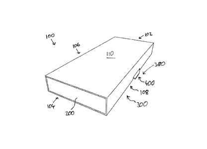
Referring to Figures 1, 2 and 3, a child resistant package 100 comprises a
support 200 for
storing hazardous materials (not shown), a structure, in the form of a sleeve
300 for blocking
access to the hazardous materials, and a latchable insert in the form of a
substantially planar
tab member 400 for latching the package 100. The package 100 comprises a rear
end 102, a
front end 104, a left side 106, a right side 108, an upper side 110, and a
lower side (not
shown).
The package 100 is moveable by a user between a fully-closed or secured
position, shown in
Figure 1, in which access to the hazardous materials is blocked by the sleeve
300, and a fully-
open or access position, shown in Figure 2, in which access to the hazardous
materials is
permitted.
CA 3020612 2018-10-11
18
The tab member 400 is coupled to the support 200 such that the tab member 400
and support
200 are movable together in an opening direction from the secured position to
the access
position.
The sleeve 300 and the tab member 400 comprise co-operating latch features,
indicated
generally at 380. The latch features 380 are configured to engage when the tab
member 400
and the support 200 are arranged in the secured position.
The components of the latchable package will now be described with reference
to Figures 4
to 6.
As best seen in Figure 4, the tab member 400 is a panel or substrate formed
from a
substantially flat sheet, which is made from a flexible cardboard or plastics
material. The tab
member 400 is planar such that it extends in a plane parallel to the lower
side of the blister-
pack when it is housed in the package 100 (see Figure 2). The panel or
substrate may be, for
example, a cut or stamped sheet, or it may be an injection moulded sheet.
A body 401 forms the majority of the tab member 400. Regions of low resistance
in the body
401, exemplified here as cut-outs 416 in the body 401 define latch members
434, which are
joined to the body 401 by live hinges 436.
The tab member 400 comprises a front edge 402, a rear edge 404, a left edge
406, a right
edge 408, an upper side 410, and a lower side (not shown).
The distance between the front and rear edges 402, 404 defines a length of the
tab member
400, and the distance between the left and right edges 406, 408 defines its
width. The spacing
between the upper side 410, and the lower side defines a thickness of the tab
member 400,
which is substantially less than its length or width.
In the embodiment illustrated, the sheet is a styrene sheet having a thickness
of approximately
1 mm and a length of approximately 12 cm. The sheet therefore has a length-to-
thickness
ratio of approximately 120:1. The sheet is of a stiffness that is great enough
to impart self-
CA 3020612 2018-10-11
19
=
supporting stiffness to the sheet (i.e. the sheet is not significantly
deformed under its own
weight), but low enough to allow the sheet to flex to some degree. The sheet
also has a yield
stress that is high enough to allow substantial flexing of the sheet without
plastic deformation.
The cut-outs 416 in the body 401 that define the latch members 434 take the
form of left and
right slots aligned respectively with left and right edges 406, 408 of the tab
member 400. The
slots 416 are elongate, being substantially oblong in shape, and extend
parallel to the left and
right edges 406, 408 along the majority of the length of those edges 406, 408.
The length of each slot 416 is substantially greater than the width of each
slot. In the
embodiment illustrated, the width of each slot 416 is approximately 2 mm, or
twice the
thickness of the tab member 400, and the length of each slot 416 is
approximately 8 cm, or
approximately forty times its width.
The elongate slots 416 terminate at front and rear ends 420, 418, which are
spaced a distance
from the respective front and rear edges 402, 404 of the tab member 400. In
the embodiment
illustrated, the elongate slots 416 have a length that is approximately 70 %
of the length of the
tab member 400, and are arranged centrally with respect to the front and rear
edges 404, 402
of the tab member 400.
In this way, the spacing between the front end 420 of the slot 416 and the
rear edge 404 of
the tab member 400 is equal to the spacing between the rear end 418 of the
slot 416 and the
front edge 402 of the tab member 400. This spacing is equal to approximately
15 % of the
length of the tab member 400.
As best seen in Figure 4, at the left and right edges 406, 408 of the tab
member 400, each
latch member 434 is provided with a latch formation 422. Each latch formation
422 is disposed
at a substantially central position on the respective left or right edge 406,
408 of the tab
member 400, and protrudes outwardly from that edge 406, 408.
The tab member 400 is symmetrical about its central longitudinal axis.
Therefore, the left and
right latch formations 422 are mirror images of each other and function
identically but in
opposite directions. It will be appreciated that the latch formations 422 are
spaced apart from
CA 3020612 2018-10-11
20
= =
one another by a distance that corresponds approximately to the width of the
tab member
400. In the embodiment shown, this distance is sufficiently large that an
adult, having relatively
large hands, could depress both latch formations 422 simultaneously using only
one hand, for
example between thumb and forefinger, but a child, having relatively small
hands, could not.
Considering for convenience the right edge 408 and right latch member 434 and
latch
formation 422 only, the latch member 434 is formed from the sheet, and hence
is formed
integrally with the body 401 of the tab member 400. Thus, the latch member 434
is of
substantially the same thickness as the body 401 of the tab member 400, and
lies in the same
plane.
The latch member 434 is an elongate beam or arm that lies outboard of the slot
416 and
encompasses a portion of the right edge 408 of the tab member 400. More
specifically, the
latch member 434 encompasses at least the portion of the right edge 408 of the
tab member
400 that includes the latch formation 422. The latch member 434 terminates
forwardly and
rearwardly in live hinges 436 that are disposed longitudinally outboard of the
respective front
and rear ends 418, 420 of the slot 416.
The spacing between the slot 416 and the right edge 408 of the tab member 400
defines the
width of the latch member 434. In the embodiment illustrated, the width of the
latch member
434 is approximately 2.5 mm, which is slightly greater than the width of the
slot 416.
Consequently, the width of the latch member 434 is large enough that the latch
member 434
is not easily broken and can provide structural support to the latch formation
422, but small
enough that the latch member 434 can be deformed easily.
Referring to Figures 4 and 5, the latch formation 422 comprises a rear edge
424, a front edge
426, and an outer edge 428. The outer edge 428 of the latch formation 422 lies
substantially
parallel to the right side 408 of the tab member 400. The perpendicular
spacing between the
outer edge 428 of the latch formation 422 and the right edge 408 of the tab
member 400
defines a width of the latch formation 422. The latch formation 422 is of a
relatively small width
compared to the width of the tab member 400: specifically, in the embodiment
illustrated, the
width of the latch formation 422 is approximately 1.5 mm, and is hence
approximately 1.5
times the thickness of the tab member 400.
CA 3020612 2018-10-11
= = 21
The rear edge 424 of the latch formation 422 extends rearwardly between the
outer edge 428
of the latch formation 422 and the right edge 408 of the tab member 400. The
rear edge 424
is tapered so as to extend simultaneously inwardly, towards a centre of the
tab member 400,
and rearwardly, towards the rear edge 404 of the tab member 400, such that the
rear edge
424 meets both the outer edge 428 of the latch formation 422 and the right
edge 408 of the
tab member 400 at an obtuse angle of approximately 165 . Thus inclined, the
rear edge 424
of the latch formation 422 defines a ramp.
The front edge 426 of the latch formation 422 also extends rearwardly between
the outer edge
428 of the latch formation 422 and the right edge 408 of the tab member 400.
The front edge
426 is inclined so as to extend simultaneously inwardly and rearwardly, such
that it meets
both the outer edge 428 of the latch formation 422 and the right edge 408 of
the tab member
400 at an acute angle of approximately 55 . In this way, the front edge 426 of
the latch
formation 422 defines an under-cut notch or a shoulder. When the tab member
400 is
arranged in the package 100 in the closed position, the shoulder abuts a
corresponding
abutment surface 352 on the sleeve 300 and so acts as a locking formation.
Where the latch formation 422 meets the right edge 408 of the tab member 400,
the spacing
between the front and rear edges 424, 426 of the latch formation 422 defines
the length of the
latch formation 422. In the embodiment illustrated, the length of the latch
formation 422 is
approximately 20 % of the length of the slot 416.
When a user applies an inward force to the latch formation 422, for example by
squeezing the
left and right latch formations 422 between their thumb and middle finger, the
latch member
434 of the tab member 400 is resiliently deformed in an inward direction.
The slot 416 allows the latch member 434 to bend inwardly about the live
hinges 436, such
that a central portion of the latch member 434 occupies the space of the slot
416. In this way,
the latch member 434 is effectively subjected to a three-point bend, with
outward bending
moments being applied at the live hinges and an opposed inward bending moment
being
applied at the latch formation 422 (i.e. at the centre of the latch member
434) by the user's
finger or thumb.
CA 3020612 2018-10-11
= = 22
The extent of deflection of the latch member 434 is therefore restricted by
the width of the slot
416. The width of the slot 416 is selected to be narrow enough that deflection
of the latch
member 434 is restricted to a degree of deflection that is within the elastic
limits of the latch
member 434.
This bending of the latch member 434 allows the latch formation 422 to be
moved in an
unlatching direction L that extends substantially orthogonally to the left and
right edges 406,
408 of the tab member 400.
In this way, the latch formation 422 is naturally and resiliently biased
outwardly in a first,
engaged position in which the front, rear and outer edges 424, 426, 428 of the
latch formation
422 protrude outwardly beyond the right edge 408 of the tab member 400. Upon
application
of an inward force to the latch formation 422 by a user, the latch formation
422 can be
resiliently moved in the unlatching direction L to a second, disengaged
position, in which the
outer edge 428 of the latch formation 422 lies substantially flush with, or
inwardly of, the right
edge 408 of the tab member 400. When the inward force is removed, the latch
formations 422
return to the first, engaged position once more.
The sheet-like configuration of the tab member 400 means that it can be formed
from a single
sheet of material, for example by a simple process of cutting or stamping. The
sheet material
itself is inexpensive, and the manufacturing process is fast, efficient and
similarly inexpensive.
Alternatively, the tab member 400 could be made by other inexpensive methods,
for example
by injection moulding a plastics material. In this way, the cost of the
package can be kept
relatively low. Furthermore, the latch-carrying component is so thin that it
takes up only
minimal space in the package when stacked with other components such as the
blister pack,
thereby reducing its size, and improving its aesthetic appeal.
Referring now to Figure 6, the support 200 comprises a main body that defines
a tray 202.
The tray 202 comprises a rear end 204, a front end 206, a left side 208, a
right side 210, and
a base 212.
CA 3020612 2018-10-11
= 23
The base 212 of the tray 202 is defined by a generally planar base wall 214.
Left and right
side walls 216, 218 are upstanding from the base wall 214 at respective left
and right sides
208, 210 of the tray 202. The front end 206 of the tray 202 is provided with a
front blocking
means 220 that defines a front wall 222 of the tray and a front blocking
surface 224 that lies
perpendicular to the front wall 222 and that extends a short distance from the
front wall 222
into the tray 202. The rear end 204 of the tray 202 is provided with a similar
rear blocking
means 226 that defines a rear wall 228 of the tray 202 and a rear blocking
surface 230 that
lies perpendicular to the rear wall 228 and that extends a short distance from
the rear wall 228
into the tray 202.
The left and right sides 208, 210 of the tray 202 are provided with elongate
apertures 232.
Each aperture 232 sits over an edge 234 defined where each side wall 216, 218
meets the
base wall 214. In this way, each aperture 232 extends a short distance up the
side wall 216,
218 and a short distance into the base wall 214.
In the assembled package 100, the apertures 232 receive the latch formations
422 of the tab
member 400 (see Figure 2).
At the rear end 204 of the tray 202, the support 200 is provided with a
withdrawal stop
formation in the form of a withdrawal stop latch 236. The withdrawal stop
latch 236 is a flap
that extends rearwardly from a lower rear edge of the tray 202. The withdrawal
stop latch 236
comprises a crease 238 where the flap 238 meets the lower rear edge of the
tray 202, and a
front edge 240 opposite the crease.
In the embodiment shown, the support 200 is made of cardboard, and is formed
by folding a
flat blank in the configuration shown. However, the support 200 may be formed
from any
suitable material and by any suitable method. For example, the support 200 may
be formed
from a plastics material such as impact styrene by vacuum forming or injection
moulding.
Referring now to Figure 7, the sleeve 300 comprises a main body 302 in the
form of a shell
that defines an interior space 303. The sleeve has a rear end 304, a front end
306, a left side
308, a right side 310, a base 312 and a top 314.
CA 3020612 2018-10-11
= 24
The base 312 and top 314 of the sleeve 300 are defined respectively by a
generally planar
base wall 316 and a generally planar upper wall 318. Left and right side walls
320, 322 join
the base wall 316 to the upper wall 318 at respective left and right sides
308, 310 of the sleeve
300.
The front end 306 of the sleeve 300 is open. At the front end 306, the base
wall 316 is provided
with a withdrawal stop latch in the form of a flap 324. The flap 324 extends
rearwardly from a
front edge 326 of the base wall 316 into the interior space 303. The
withdrawal stop latch 324
comprises a crease 325 where the flap 324 meets the front edge 326 of the base
wall 316,
and a rear edge 327 opposite the crease 325.
The rear end 304 of the sleeve 300 is partially closed by a rear end wall 328.
The rear end
wall 328 comprises a cut-out that defines an access opening 330 in the rear of
the package
100.
The cut-out 330 extends only partially along the width of the rear end wall
328 and only
partially up the height of the rear end wall 328. In this way, the rear end
wall 328 of the
structure 300 defines side closure portions 332 that extend between the cut-
out 330 and side
edges 334 of the rear end wall 328 and a top closure portion 336 that extends
between the
cut-out 330 and a top edge 338 of the rear end wall 328.
At the base 312 of the sleeve 300, the base wall 316 is provided with a
channel 340 defined
by a cut-out in the base wall 316. The channel 340 extends from a rear edge
347 of the base
wall 316 forwardly towards the front end 306 of the sleeve 300.
The channel 340 has a length in the opening direction that is greater than its
width in a
direction perpendicular to the opening direction. More specifically, the
length of the channel is
at least 1.5 times the width of the channel, and is preferably approximately
twice the width of
the channel.
The channel 340 extends only partially across the width of the base wall 316,
and only partially
along the length of the base wall 316. In this way, the base wall 316 of the
sleeve 300 defines
side closure portions 342 that extend between the channel 340 and left and
right side edges
CA 3020612 2018-10-11
25 =
344 of the base wall 316 and a front closure portion 346 that extends between
the channel
340 and the front edge 326 of the base wall 316.
In the embodiment shown, the cut out that defines the access opening 330 and
the cut out
that defines the channel 340 are continuous with one another so as to define a
single cut-out
that straddles the rear edge 347 of the sleeve 300 to define both access
opening 330 and the
channel 340.
At the left and right sides 308, 310 of the sleeve, the base wall 316
comprises left and right
side edges 344 defined where the base wall 316 meets the left and right side
walls 320, 322.
Each side 308, 310 of the sleeve is provided with an elongate aperture 348
that straddles the
respective left or right side edge 344. In this way, each elongate aperture
348 extends a short
distance up the side wall 320, 322 and extends a short distance into the base
wall 316.
An edge surface 350 surrounding the aperture 348 comprises a front edge that
defines an
abutment surface or abutment edge 352 on the sleeve 300. In use, the latch
formation 422 on
the tab member 300 abuts against the abutment edge to engage with the latch
formation 422,
thereby preventing movement of the tab member 300 and hence the support 200.
Each aperture 348 is disposed centrally between the front and rear ends 308,
310 of the
sleeve 300, and is of a length that is slightly greater than the length of a
latch formation 422
of the tab member 400. In this way, in the assembled package 100, the latch
formation 422
can be received in the aperture 348.
In the embodiment shown, the sleeve 300 is made of cardboard, and is formed by
folding a
flat blank in the configuration shown. However, the sleeve 300 may be formed
from any
suitable material and by any suitable method. For example, the support 200 may
be formed
from a plastics material such as impact styrene by vacuum forming or injection
moulding.
The construction and operation of the fully-assembled package will now be
described in more
detail with reference to Figures 8 and 9.
CA 3020612 2018-10-11
= = 26
Referring to Figure 8, in the assembled package 100, the tab member 400 is
arranged inside
the tray 202 of the support 200. In this way, the support 200 and the tab
member 400 together
define a support arrangement 500.
The tab member 400 is arranged at the base 212 of the tray 202. In this way,
the tab member
400 takes up only a very small volume of the tray that would otherwise be
available for holding
items. Each latch formation 422 of the tab member 400 protrudes through the
respective
aperture 232 at the side of the tray 202. In this way, the latch formation 422
is accessible
through the tray 202.
The support arrangement 500 is slidably arranged inside the interior space 303
defined by the
sleeve 300 so that the support 200 and the tab member 300 can be moved back
and forth
together between the access position and the secure position (see Figures 1
and 2).
As best seen in Figures 9A and 9B, when the support 200 and the tab member 400
are
arranged in the secure position, the latch formations 422 on the tab member
400 protrude
through the apertures 348 on the sleeve 300. Together, the latch formations
422 of the tab
member 400 and the abutment surfaces 352 on the wall surrounding the apertures
348 of the
sleeve 300 define the co-operating latch features 380 that engage when the
support 200 and
the tab member 400 are in the secure position.
The support 200 and sleeve 300 each have features that contribute to the child-
resistance of
the package and make it difficult for a child to access the contents of the
tray 202 when the
package 100 is secured.
Referring back to Figure 6, the blocking means 220, 226 on the tray 202 of the
support act to
block the ends of the package 100 to make it difficult for a child to access
the contents of the
tray 200 when the package is secured. In particular, front and rear walls 222,
228 block the
open end at the front of the package 100 and the access opening 330 at the
rear of the
package 100, and the blocking surfaces 224, 230 lie flush against the upper
wall 318 of the
sleeve 300 to prevent a child accessing the tray by working a finger over the
front or rear wall
222, 228.
CA 3020612 2018-10-11
27
The closure portions 332, 336, 342, 346, of the rear and base walls 328, 316
of the sleeve
300 (see Figure 8) also act to obstruct access the contents of the tray 200
when the
package 100 is secured, whilst still providing the aperture 330 that defines
the access
opening 330 and channel 340. In particular, the closure portions block access
to any gaps
between the sides and top of the tray 202 and the interior surface of the
sleeve 300, thereby
preventing a child working a finger between the tray and the sleeve to access
the contents.
Referring now to Figure 10, when the package 100 is secured and the latch
formations 422
are in the engaged state, they are located in the apertures 348 of the sleeve
300, with the
front edges 426 of the latch formations 422 protruding into the apertures, and
facing the
abutment surfaces 352 on the walls surrounding the apertures 348.
If a user attempts to move the support and hence the tab member 400 in the
direction of arrow
X when the latch formations 422 are in their engaged state, the front edges
426 of the latch
formations 422 bear against the respective abutment edges 352 of the apertures
348, as
shown in Figure 14B, which prevents movement of the tab member 400 in the
direction of
arrow X. If a user continues to attempt to force the support and hence the tab
member in the
direction of arrow X once the front edges 426 of the latch formation 422 are
already bearing
against the abutment edge 352 of the apertures 328, the inclination of the
front edge 426 of
the latch formation 422 forces the latch formations 422 outwardly, further
away from the
disengaged state.
Movement of the support 200 and hence the tab member 400 in direction X can
only occur
when the latch formations 422 are simultaneously brought into their disengaged
state by a
user pressing the latch formations 422 towards each other in a squeezing
action between a
user's thumb and middle finger, as shown in Figure 11. As the user squeezes
the latch
formations 422, the latch members 434 move in the unlatching direction L,
which is
substantially orthogonal to the side edges 406, 408, and is in the plane of
the tab member
400. The latch members are retained in this plane at least in part by the 214
of the tray 202.
In other words, the base wall of the tray (visible in Figure 6) acts to
counteract any out-of-
plane flexibility of the sheet to retain the latch members 434 in the plane of
the tab member
400.
CA 3020612 2018-10-11
28
=
By moving the latch members 434 in the unlatching direction, the latch members
434 are
moved into the disengaged state. In the disengaged state, the front edges 426
of the latch
formations 422 are arranged inwardly of the side walls of the sleeve 300. In
this way, when
the user moves the tab member 400 in the direction of arrow X, the front edges
426 of the
latch formations 422 do not abut the abutment edges 352 of the apertures 328,
and the tab
member 400 and hence the support 200 are free to slide within the sleeve 300
in the opening
direction X.
Once the user has moved the latch formations 422 in the unlatching direction
so that the latch
formations 422 are in the disengaged state, the support 200 must be pushed in
the opening
direction X to open the package 100. To this end, whilst pinching the latch
formations 622
between a user's thumb and middle finger, the user employs another finger of
the same hand,
for example the forefinger, to access the support 200 through the access
opening 330 at the
rear of the package 100. The user pushes the support 200 in the opening
direction X to move
the latch formations 422 into a position inside the side walls 320, 322 of the
sleeve 300. In
other words, the user pushes the support 200 using the access opening 330 in
the opening
direction X until the support 200 and hence the tab member 400 have been moved
just away
from the secured position.
Referring back to Figure 9B, after the support 200 and tab member 400 have
been moved just
away from the secured position, the user continues pushing the support 200
further in the
opening direction X using their forefinger. To achieve this, the user's
forefinger must follow
the channel 340 in the base wall 314 of the sleeve 300. By virtue of the
channel 340 the user's
forefinger can remain in continuous contact with the support 200 to push it in
the opening
direction X, until the user's forefinger reaches the end of the channel 340.
At that point, the
support 200 has been moved towards to access position to a sufficient extent
that the user
can access the contents of the tray 202.
The latch formations 422, access opening 330 and channel 340 are all
positioned to enable
the user to disengage the latch formations 422 and simultaneously push the
tray in the
opening direction X using a single hand. To this end, the spacing between the
latch formations
422 in a direction perpendicular to the opening direction is no greater than
the typical thumb-
to-middle-finger span of an adult hand (for example, no greater than 13 cm
which is a
CA 3020612 2018-10-11
29
=
maximum span of a typical adult, or more preferably no greater than 10.5 cm),
and the spacing
between the latch formations 422 and the access opening 330 in a direction
parallel to the
opening direction is no greater than the typical thumb-to-forefinger span of
an adult hand (for
example, no greater than 12 cm).
The presence of the channel 340 allows the user to continue pushing the
support 200 in the
opening direction using a single hand. The contents of the tray can be
accessed when the
package has been opened as much as the channel 340 will allow. Alternatively,
the package
can be opened fully, for example using a two-handed operation in which a user
holds the
sleeve 300 with one hand and pulls the front end of the support 200 with the
other hand.
The need to squeeze the latch formations 422 together whilst simultaneously
accessing and
pushing the support 200 via the access opening 330 and channel 340 requires a
level of
dexterity that is difficult for children, but that is easy for adults. It is
therefore very difficult for
a child to open the package, while an adult can easily open the package using
only one hand.
The latch formations 422, access opening 330 and channel 340 therefore work in
synergy to
provide a package that is child-resistant and yet can be easily opened with
one hand.
The latchable insert in the form of the tab member 200, in conjunction with
the apertures on
the sleeve 300, acts to provide child resistant functionality to the package
100 whilst taking up
very little space within the package.
Referring to Figures 13 and 14, further movement of the support 200 in the
opening direction
brings the support 200 and the tab member 400 into the fully-open state. In
this fully-open
state, the withdrawal stop latches 324, 336 on the sleeve 300 and the support
200 engage
with one another to prevent further movement of the support 200 in the opening
direction.
In particular, when the withdrawal stop latches 324, 336 are engaged, the
front edge 240 of
the withdrawal stop latch on the support 236 abuts against the crease 325 of
the withdrawal
stop latch 324 on the sleeve, and/or the rear edge 327 of the withdrawal stop
latch 324 on the
sleeve 300 abuts against the crease 238 of the withdrawal stop latch 236 on
the support 200.
CA 3020612 2018-10-11
= 30
=
In this way, the withdrawal stop latches 324, 336 act to limit movement of the
support 200 in
the opening direction, so that the support 200 and the tab member 400 cannot
be easily
removed from the sleeve 300.
To return the support 200 from the fully-open state the user simply pushes the
support 200
back into the sleeve 300. As the support 200 is pushed into the sleeve 300,
the side walls
320, 322 of the sleeve 300 initially push the left and right latch formations
422 into the
disengaged state. The ramp-like taper of the rear edges of the latch
formations 422 enables
this inward movement. However, when the latch formations 422 reach their
associated
apertures 348 in the side walls 320, 322, they are biased into the engaged
state. Thus, the
left and right latch formations 422 engage in a snap fit with the sleeve 300
when the support
200 is returned into the sleeve 300 in direction X. The snap fit gives a clear
indication to the
user that the package 100 has been returned to the fully-closed state, and can
therefore be
stored safely.
A method of making the package 100 described above by assembling its component
parts will
now be described with reference to Figures 15A to 15D.
Referring to Figure 15A, the support 200 is first provided. The support may be
provided by
folding a blank on site to form the desired support configuration.
Alternatively the support may
pre-fabricated off-site, by folding a blank or by another method, such as a
moulding process
that results in a moulded support component.
Referring to Figure 15B, the tab member 400 is then coupled to the support
200. In this case,
the tab member 400 is inserted into the tray 202 of the support 200 so that
the tab member
400 defines the base of the tray 202 and the latch formations 422 of the tab
member 400
protrude through the apertures 232 of the support 200. The tab member may
additionally be
adhered to the base of the tray 202 if required.
As the tab member 400 is inserted into the tray, the side walls 216, 218 of
the tray 202 exert
a force on the latch formations 422 in the unlatching direction to move the
latch formations
422 into the disengaged state during insertion. Once the tab member 400
reaches the base
CA 3020612 2018-10-11
31
of the tray, the latch formations 422 align with the apertures 232 and the
latch formations 422
are free to spring outwardly into the engaged position in a snap fit.
Next, as shown in Figure 150, the support 200 and tab member 400 are inserted
into the
sleeve. To insert the support 200, the rear end of the support 200 is pushed
into the open end
at the front of the sleeve 300 in a closing direction Y that is opposite to
the opening direction
X.
The support 200 and tab member 400 are pushed further into the sleeve 300
until the support
200 reaches the secure position, as shown in Figure 15D. Once the support 200
reaches the
secure position, the latch formations 422 snap fit into the apertures 348 in
the sleeve 300 and
the assembly process is complete.
In this way, a child resistant package can be simply and easily manufactured
by inserting a
latchable insert in the form of a planar tab member 400 into a support 200. To
confer child-
resistant functionality, it is necessary only to couple the latchable insert
to the support, in this
case by inserting the latchable insert 400 into the support, and thus only one
additional
process step is required to assemble the package.
A particular advantage of the use of the latchable insert 400 to confer child
resistance is that
the process is easily scalable. A small run of such packages can be easily
achieved with
relatively little investment, since the only additional part required is the
latchable insert 400
which can be bought on a small scale if necessary. Cardboard blanks making up
the sleeve
300 and the support 200 need only be modified by addition of apertures, and
this modification
can be easily made when the blank is cut or stamped. In this way, a package
manufacturer
can easily make small runs of the latchable package, for example for testing
purposes,
economically and without significant investment. Conversely, the process can
be easily scaled
up to a large-volume output if required.
Furthermore, the planar nature of the tab member means that the tab member can
be
accommodated in the tray 202 of the support 200 whilst taking up very little
space that would
be otherwise available for holding items in the tray. In this way, the child
resistant functionality
has a negligible impact on the size and capacity of the package.
CA 3020612 2018-10-11
32
It will be appreciated that the feature of the latchable insert 400, and the
features of the access
opening and channel may be used independently of one another.
For example, the access opening and channel may be omitted to provide a
package with a
latchable insert that is intended to be opened in a two-handed operation.
Alternatively, the latchable insert may be omitted and the latch formations,
and hence the
child-resistant functionality may be integrated directly with the support.
Alternative embodiments, in which the child-resistant functionality is
integrated with the
support rather than provided by means of a separate latchable insert, will now
be described
with reference to Figures 16 to 19.
Figures 16 and 17 illustrate a first alternative embodiment of a package 1100.
The package
comprises a support arrangement 1200 (shown in isolation in Figure 16) and a
structure in the
form of a sleeve 1300.
The sleeve 1300 is substantially the same as the sleeve 300 already described
above.
The support arrangement 1200 is similar to the support 200 described above but
differs in that
the support arrangement 1200 has integrated child-resistant functionality.
In particular, the base wall 1214 of the tray 1202 adopts a structure that
matches the structure
.. of the tab member described above. In this way, elongate cut outs 1242,
latch members 1244,
and latch formations 1246 are provided on the base wall 1214 of the tray 1202.
The latch
formations 1246 protrude beyond side walls 1216, 1218 of the tray 1202 so that
the latch
formations 1246 can protrude into the apertures 1348 on the sleeve 130 and
abut against
abutment surface 1352 on the wall surrounding the aperture 1348. The latch
formations 1246
.. of the base wall 1214 operate in substantially the same way as the latch
formations 422 of the
tab member 400 described above.
CA 3020612 2018-10-11
33
In the vicinity of the latch formations 1246, the side walls 1216, 1218 of the
tray 1202 are
provided with elongate apertures 1248 towards the base of the side walls 1216,
1218. These
elongate apertures 1248 sever the latch members 1244 from the side walls 1216,
128,
allowing the latch members 1244 to have the flexibility required to move the
latch members in
the unlatching direction.
Operation of the package is substantially the same as described above. In
particular, the latch
formations 1246 act together with the access opening 1330 and channel 1340 to
provide the
combination of child resistance and one-handed operation described in relation
to the package
.. 100 above.
The tray 1202 of this embodiment is formed of a plastics material, for example
by injection
moulding.
Figures 18 and 19 illustrate a second alternative embodiment of a package
2100. The package
comprises a support arrangement 2200 (shown in isolation in Figure 18) and a
structure in the
form of a sleeve 2300.
The sleeve 2300 is substantially the same as the sleeve 300 already described
above.
The support arrangement 2200 is similar to the support 200 described above but
differs in that
the support arrangement 2200 has integrated child-resistant functionality.
In this case, the support arrangement 2200 comprises a main body in the form
of a shell 2202
that is substantially tray-shaped. The shell 2202 is formed of a plastics
material by vacuum
moulding. The tray comprises outer front and rear walls 2204, 2206 joined by
outer side walls
2208 that define an external perimeter of the tray 2202, and internal front
and rear walls 2210,
2212 joined by internal side walls 2214 that define an internal perimeter of
the tray 2202. A
base wall 2216 joins the internal walls 2210, 2212, 2214 at their base.
At the top surface of the tray 2202, the outer front wall 2204 and outer rear
wall 2206 are
joined respectively to the inner front wall 2210 and the inner rear wall 2212
by blocking
surfaces 2218 which perform the same function as the blocking surfaces
described in relation
CA 3020612 2018-10-11
= 34
=
to the package of Figures 1 to 15 above. Also at the top surface, the outer
side walls 2208 are
joined to the inner side walls 2214 by side portions 2220 of the top surface.
Around the outer perimeter of the shell 2202 is a rim 2222 that extends
perpendicularly and
outwardly in all directions from the outer walls 2204, 2206, 2208. At each of
the left and right
sides, the rim 2222 is provided with a latch formation 2224 that is of
substantially the same
shape as the latch formation described in relation to the package of Figures 1
to 15 above.
The outer walls 2204, 2206, 2208 of the shell are flexible, by virtue of being
thin (typically less
than 0.5 mm) and being made of a flexible plastics material. In this way, the
left and right side
walls 2208 together with the associated rim 2222 and latch formations 2224,
define a
resiliently deformable latch member. In particular, the join between the side
wall 2208 and the
side portion 2220 of the top surface acts as a live hinge 2226. Pushing the
latch formations
2224 in the unlatching direction L causes the side walls to hinge about these
live hinges 2226
so that the latch formations move inwardly from the latched configuration to
an unlatched
configuration.
In the assembled package 2100, the support arrangement 2200 is housed inside
the sleeve
2300. When the support arrangement 2200 is in the secured position, the latch
formations
2224 protrude through apertures 2348 on the sleeve 2300 and abut against
abutment edges
2352 on the wall surrounding the aperture 2348 in the manner already described
above.
Operation of the package is substantially the same as described above. In
particular, the latch
formations 2246 act together with the access opening 2330 and channel 2340 to
provide the
combination of child resistance and one-handed operation described in relation
to the package
100 above.
Figures 20 and 21 illustrate a further embodiment of a package 3100. The
embodiment of
Figures 20 and 21 is similar to the embodiment of Figures 1 to 15 and differs
only in that the
access opening 3330 and the channel 3340 are arranged differently.
In this embodiment, the access opening 3330 is provided in the base wall 3316
of the structure
3300. The base wall 3214 of the support 3200 is provided with a grip feature
in the form of an
CA 3020612 2018-10-11
35
aperture 3250, and when the package 3100 is secured as shown in Figure 20, the
aperture
3250 in the base wall 3214 of the support 3200 aligns with the access opening
3330 in the
base wall 3316 of the structure 3300. The aperture 3250 in the base wall 3214
of the support
3200 is surrounded by an edge surface 3352.
The channel 3340 is also provided in the base wall 3316 of the structure. The
channel 3340
is contiguous with the access opening 3330, such that the access opening 3330
and the
channel 3340 are defined by the same cut-out 3350. The channel 3340 extends
from the
access opening 3300 in the opening direction.
To open the package, a user squeezes the latch formations 3422 in the manner
already
described in relation to the package of Figures 1 to 15. The user then pushes
the support by
inserting a finger, for example a forefinger, through the access opening 3330
in the structure
3300 and into the aperture 3250 in the support 3200. The user then pushes
their forefinger
against the edge 3252 of the base wall 3214 surrounding the aperture 3250 to
move the
support 3200 in the opening direction. The user continues to push the support
3200,
whereupon the user's forefinger enters the channel, and follows the channel in
the opening
direction while continuing to push the support 3200. When the user's finger
reaches the end
of the channel 3340 the package has been at least partially opened.
The aperture 3250 in the support 3200 could be replaced with an alternative
grip feature such
as a protrusion or button, which may have a high-friction surface. In this
case, the protrusion
is accommodated in the channel as the support 3200 is moved in the opening
direction.
Figure 22, Figure 23 and Figures 24a to 24c illustrate alternative tab members
that may be
incorporated into a package of the invention in place of the tab members
described above.
In the tab member 4400 of Figure 22, the region of low resistance that defines
each latch
member 4434 is defined by a longitudinal channel 4416 formed in the body 4401
of the tab
member 4400 adjacent to the latch member 4434. The channel 4416 is defined by
a fold in
the body 4401 of the tab member 4400, with the fold protruding out of the
plane of the tab
member 4400 in a direction that, in use, extends into the support.
CA 3020612 2018-10-11
= = 36
When a user squeezes the latch members 4434 between thumb and forefinger,
sides of the
channels 4416 are squeezed together, thereby allowing the latch members 4434
to move in
the unlatching direction.
By virtue of the fold construction, on a side of the tab member 4400 that is
opposite to the
channel, each fold defines a protrusion or ridge 4417. The ridges 4417 act to
increase the
bending stiffness of the tab member 4400 and thereby improve its durability.
It will be appreciated that the tab member 4400 could be inverted, in which
case the channels
4416 would be similarly inverted to define an inverted channel or a ridge.
The tab member 5400 of Figure 23 comprises a channel 5416 that extends around
a perimeter
of the tab member 5400, slightly inboard from its edges. The channel 5416
comprises left and
right longitudinal sections 5416a and front and rear transverse sections 5416b
that join the
longitudinal sections 5416a.
As with the embodiment of Figure 22, an underside of the channel 5416 defines
a ridge 5417.
Undersides of the longitudinal channel sections 5416a define longitudinal
ridge sections
5417a that increase bending stiffness as in the tab member 4400 of Figure 22.
Undersides of
the transverse channel sections 5416b define transverse ridge sections 5417b
that provide
additional torsional stiffness to the tab member 5400.
As with the embodiment of Figure 22, it will be appreciated that the tab
member 5400 could
be inverted, in which case the channels 5416 would be similarly inverted to
define an inverted
channel or a ridge.
The tab member 6400 of Figure 24a does not comprise a region of low
resistance. Instead,
the latch member 6434 is integral with the body 6401 of the tab member 6400.
In this
embodiment, the body of the tab member 6401 is sufficiently flexible that the
tab member
6401 can bend out-of-plane.
When the latch formations 6422 are in the engaged state, the tab member 6400
is
substantially planar as shown in Figure 24b. To move the latch formations 6422
in the
CA 3020612 2018-10-11
37
unlatching direction and into a disengaged state, a user squeezes the latch
members 6434
between thumb and fore finger, and the inward force causes the body 6401 of
the tab member
6400 to deflect out of the plane of the tab member 6400 into an arc. The
deflection causes
the latch formations 6422 to move inwardly towards one another in the
unlatching direction.
Figures 25a to 25c illustrate an alternative tab member 7400 coupled to a
support 7200.
The tab member 7400 is optionally hingedly coupled to the support 7200 via a
hinge coupling
7450. In the embodiment shown, the support 7200 and tab member 7400 are
integrally
formed, for example from a thermo-formed sheet or an injection-moulded sheet,
and the hinge
7450 is defined by a crease or fold.
Embodiments are also envisaged in which the support 7200 and tab member 7400
are formed
from separate pieces and the hinged coupling is omitted.
The tab member 7400 comprises two portions: a root portion 7400a and a lid
portion 7400b.
The root portion 7400a is coupled to the support 7200 via a coupling means
7460 that will be
described in detail later. The root portion 7400a is hingedly connected to the
lid portion 7400b
via a hinge 7452 defined by a crease, fold, score or perforation at the
boundary between the
sections. In this way, the lid portion 7400a is movable with respect to the
root portion 7400b
and hence the support 7200 between a closed configuration in which the lid
portion 7400a
blocks access to the support 7200, and an open configuration in which access
to the support
7200 is permitted. The lid portion 7400b can be retained in the closed
position by a retaining
means 7480 that will be described in detail later.
The coupling means 7460 that couples root portion 7400a to the support 7200
will now be
described in further detail, with reference to Figure 25c.
As can be seen in Figure 25a, the coupling means 7460 comprises a channel 7416
that
extends around a perimeter of the root portion 7400a. The channel 7416
comprises left and
right longitudinal channel portions 7416a that extend in the opening direction
of the package.
Undersides of the channels 7416a define ridges 7416b.
CA 3020612 2018-10-11
38
As shown in Figure 25c, when the root portion 7400a is coupled to the support
7200, the
ridges 7416b, sit between side walls 7216, 7218 of the support 7200. More
particularly, a
spacing between a left-most or outer side wall 7417a of the left protrusion,
and a right-most
or outer sidewall 7417b of the right protrusion is substantially the same as a
spacing between
the side walls 7216, 7218 of the support. In this way, the ridges fit snugly
between the side
walls 7216, 7218 in a push fit to couple the tab member 7400 to the support
7200.
Referring to Figure 25d, the retaining means 7480 of the lid portion 7400b
that retains the lid
portion 7400b in the closed configuration is of substantially the same
construction as the
coupling means 7460 that couples root portion 7400a to the support 7200.
In particular, the retaining means 7480 comprises a channel 7486 that extends
around a
perimeter of the lid portion 7400b.
The channel 7486 comprises left and right longitudinal channel portions 7486a
that extend in
the opening direction of the package. Undersides of the channels 7486a define
ridges 7486b.
When the lid portion 7400b is in the closed configuration, the ridges 7486b,
sit between side
walls 7216, 7218 of the support 7200. More particularly, a spacing between a
left-most or
outer side wall 7487a of the left ridge, and a right-most or outer sidewall
7487b of the right
ridge is substantially the same as a spacing between the side walls 7216, 7218
of the support.
In this way, the ridges fit snugly between the side walls 7216, 7218 in a push
fit to hold the lid
portion 7400b in the closed position.
The channel 7486 further comprises front and rear transverse channel portions
7486c that
extend perpendicular to the opening direction of the package. Undersides of
the transverse
channels 7486c define transverse ridges 7486d.
When the lid portion 7400b is in the closed configuration, the transverse
ridges 7486d sit
between front and rear walls 7212, 7214 of the support 7200. More
particularly, a spacing
between a front-most or outer wall of the front ridge, and a rear-most or
outer wall of the rear
ridge is substantially the same as a spacing between the front and rear walls
7212, 7214 of
CA 3020612 2018-10-11
39
the support. The ridges fit snugly between the front and rear walls 7212, 7214
in a push fit to
hold the lid portion 7400b in the closed position.
In this way, the lid portion 7400b defines a complete seal with the support
around its entire
perimeter. This is particularly beneficial if the support holds, for example
fresh goods, which
require an air-tight seal.
Figures 26a and 26b show the tab member 7400 and support 7200 integrated into
a package
7100. As can be seen in Figure 26a, when the package is closed, both the root
portion and lid
portion are housed within the sleeve 7300 of the package 7100 to prevent
access to the
support 7200.
As shown in Figure 26b, when the support is moved in the opening direction and
the package
is brought into the open configuration, the root portion 7400a of the tab
member remains within
the sleeve 7300, while the lid portion 7400b is accessibly clear of the
sleeve.
More specifically, when the package is in the open configuration, the hinge
7452 between the
root portion 7400a and the lid portion 7400b aligns with an end of the sleeve.
In this way, the
lid portion 7400b can be disengaged from the support 7200, for example by
pulling upwardly
on the rim of the lid portion 7400b, and can be lifted about the hinge 7452 to
move the lid
portion 7400b into an open configuration to access material inside the
support.
Figures 27a to 27c show an alternative tab member 8400 that is similar to the
tab member
7400 of Figure 26a, except that the body of the tab member 8401 comprises an S-
shaped fold
arrangement that serves to define both a retaining means 8480 and a region of
low resistance
that defines the latch member 8434.
More particularly, around a perimeter of the root portion 8400b of the tab
member 8400, the
body 8401 of the tab member 8400 is folded into a fold that defines an 'S-
shaped' cross
section. Moving from an outside edge of the perimeter inwards, the body 8401
is first folded
upwardly out of the plane of the tab member in a direction away from the
support, and is
subsequently folded downwardly out of the plane of the tab member in a
direction towards the
support.
CA 3020612 2018-10-11
40
In this way, if viewed from above, the retaining means 8480 successively
defines a ridge 8482
that protrudes away from the support and a channel 8484 that protrudes into
the support, the
channel and the ridge being adjacent to one another.
The ridge 8482 defined by the upward fold (which it will be appreciated when
viewed from
below would have the appearance of a channel) provides the region of low
resistance that
defines the latch member 8434 and facilitates movement of the latch feature
8422 in the
unlatching direction, in the same manner as the region of low resistance
described in relation
to Figure 22 and 23 above.
The channel 8484 defined by the downward fold (which it will be appreciated
when viewed
from below would have the appearance of a ridge), acts as the retaining means
that retains
the lid portion 8400b in the closed configuration in the same manner as the
retaining means
7480 described in relation to Figure 25d above, providing a push fit with the
support
A particular advantage of configuring the tab member 8400 such that the upward
fold that
defines the region of low resistance is outboard of the downward fold that
defines the retaining
means, is that the ridge defined by the upward fold can be deformed to effect
unlatching of
the latch formation without interfering with the position of the downward fold
that forms the
retaining means, thereby allowing the package to be unlatched without
compromising the seal
between the lid portion 8400b and the support 8200.
Figures 28a to 28b show a further embodiment of a tab member 9400 for use in
the package.
The tab member comprises a root portion 9400a and a lid portion 9400b. Each of
the root
portion 9400 and lid portion 9400b comprise a rim 9480 at the outer edge of
the respective
portion, the rim 9480 being defined by an upward fold that defines an inverted
channel. The
fold defines sidewalls of the rim and a top wall that extends between the side
walls. Between
the rim 9480 of the root portion 9400a and the rim 9480 of the lid portion
9400b is a channel
or groove 9482 that acts as a hinge.
The rims 9480 define a coupling means on the root portion 9400a and a
retaining means on
the lid portion 9400b. The rim is configured to sit over the sidewalls and
front and rear walls
CA 3020612 2018-10-11
. 41
=
of the support so as to form a seal over the support. In particular, the walls
of the support are
sized to fit snugly between the inner sidewalls of the rim to define a seal.
This acts firstly to
couple to root portion 9400a to the support 9200, and secondly to retain the
lid portion 9400b
in the closed position with respect to the support 9200.
The fold of the rim 9480 provides the region of low resistance that defines
the latch member
9434. The latch formations 9422 are supported on outer side walls of the rim
9480. Squeezing
the latch formations 9422 together causes the outer side walls to move
together, thereby
causing the latch formations 9422 to move in the unlatching direction.
Figure 28c shows the support 9200 in isolation and reveals that the sidewalls
of the support
comprise a detent 9280 that accommodates the groove or channel 9482 between
the root
portion 9400a and the lid portion 9400b. In this way, the tab member 9400 can
be pushed
over the walls of the support 9200 until the top wall of the rim 9480 of the
tab member 9400
contacts the walls of the support 9200, with the groove or channel 9482 of the
tab member
9200 being accommodated in the detent 9280 in the support 9200.
Figures 29a and 29b show an insert arrangement 10800 for use with the support.
The insert
arrangement comprises an insert defined by a tab member 10400 that is
substantially the
same as the insert of Figure 4, and a sleeve 10600 that houses the insert.
The sleeve 10600 is substantially flat and defines a passage that receives the
insert 10400.
The sleeve 10600 comprises apertures 10610 in its left and right sides,
through which the
latch formations 10422 of the tab member 10400 protrude.
The sleeve may be made from cardboard and may be printed, for example with
information
or promotional material.
The sleeve 10600 comprises a root portion 10600a and a lid portion 10600b, the
root portion
10600a being coupled to the support and the lid portion 10600b being moveable
relative to
the root portion 10600a to move between closed and open configurations. The
sleeve
comprises a hinge 10620 between the root and lid portions.
CA 3020612 2018-10-11
42
In use, as shown in Figure 29c, the sleeve 10600 is coupled to the support
10200. The
coupling between the sleeve 10600 and the support indirectly couples the tab
member 10400
to the support 10200.
At one end, the sleeve 10600 defines a flap 10650 that is hingedly connected
to a part of the
sleeve 10600 that houses the insert. When integrated into the package, the
flap 10650 can
act as a stop formation of the type that has already been described above, to
limit withdrawal
of the support.
It will be appreciated that stop formations in the form of flaps or other
suitable constructions
can be provided on any of the tab members described above.
In the embodiments shown, the child resistance provided by the latches is
augmented by the
fact that the spacing between the latch formations is great enough that a
child could not easily
depress both latch formations simultaneously with one hand. However, this
width of the
package merely augments the child resistance, and is not a necessary feature.
For example,
in relatively small packages, the width of the package may not be large enough
to augment
the child resistance in this manner, and in such small packages the presence
of the latches is
sufficient to provide ample child resistance.
Although in the embodiments described the package is provided with two latch
members and
two latch formations, it will be appreciated that in some embodiments only a
single latch
formation and/or latch member need be provided. In other embodiments, more
than two latch
formations or latch members may be provided. For example, a single latch
member may
support more than one latch formation. In another embodiment, each side of the
tab member
may have two slots that provide two latch members, and each latch member may
support one
of more latch formations. The latch formations need not be provided at a
central position, but
may be provided at any suitable location, for example, towards the front or
rear end of the
package.
In embodiments where a latchable insert is used, the insert need not be placed
in the base of
the support, but may be in any suitable position. For example, the insert may
be arranged
above the support such that the insert defines a lid for the tray.
CA 3020612 2018-10-11
43
The latchable insert may be coupled to the support by any suitable means that
allows
movement of the support to effect movement of the insert in the same
direction. For example,
the insert may be adhered to the support, mechanically attached to the
support, or carried by
the support to effect the coupling.
It should be appreciated that various other modifications and improvements can
be made
without departing from the scope of the invention as defined in the claims.
CA 3020612 2018-10-11