Note: Descriptions are shown in the official language in which they were submitted.
CA 03020881 2018-10-12
WO 2017/180632 PCT/US2017/027023
Pressure Cycle Actuated Injection Valve
CROSS-REFERENCE TO RELATED APPLICATIONS
This application claims priority to provisional U.S. patent application serial
number
62/321,557 filed April 12, 2016, the entire contents of which is hereby
expressly incorporated by
reference thereto.
I. BACKGROUND OF THE INVENTION
1. Field of the Invention
[0001] This invention relates to a dual barrier pressure cycle actuated
injection valve
(DBPCAIV) that is used as a substitute for gas charged, deep set surface
controlled subsurface
safety valves currently in use for providing a safety valve in conjunction
with a barrier valve in
subsea oil/gas wells.
[0002] The DBPCAIV is positioned adjacent a stab at the end of a tubular
string for providing a
flow passage in the subsea well. The DBPCAIV is designed to accommodate a
plurality of
pressure cycles to facilitate testing at a pressure downhole gage (PDG).
II. BRIEF SUMMARY OF THE INVENTION
[0003] The DBPCAIV of the present invention includes an injection valve having
a flapper
closure valve at its downhole end and also includes a variable orifice insert.
[0004] The DBPCAIV together with a traditional barrier valve provide a dual
barrier during
installation.
[0005] Tubing pressure cycles close the valve and enable pressure testing at a
pressure downhole
gage. One or more additional pressure cycles reopen the injection valve and
lock out its internal
hydraulic piston. With pressure functionality disabled within the injection
valve, pressure cycling
that is required to open the barrier valve can proceed. When the barrier valve
is opened, flow alone
operates the safety valve during normal operation.
[0006] The injection valve includes an upper indexing sleeve that includes a
plurality of groove
segments on its outer surface. A pin fixed in the injection valve housing will
cause the indexing
sleeve to rotate in response to pressure cycles.
- 1 -
CA 03020881 2018-10-12
WO 2017/180632 PCT/US2017/027023
[0007] After a given number of pressure cycles the pin will constrain the
axial movement of the
indexing sleeve which in turn will lock out movement of a piston which is
adapted to move a flow
tube.
[0008] The injection valve also includes a lower indexing sleeve which also
includes a plurality
of groove segments that interact with a stationary pin to rotate the lower
indexing sleeve through a
plurality of pressure cycles. Once the barrier valve is open, the lower
indexing sleeve is axially
movable to an amount sufficient to open and close the flapper valve element
during flow cycles of
the injection fluid.
III. BRIEF DESCRIPTION OF SEVERAL VIEWS OF THE DRAWINGS
[0009] For a detailed description of the preferred embodiments of the
invention, reference will
now be made to the accompanying drawings in which:
[0010] Figure 1 is a schematic view of an injection valve according to an
embodiment of the
invention positioned adjacent to the polished bore receptacle of the well.
[0011] Figure 2 is a schematic of the injection valve and tubing positioned
within the polished
bore receptacle.
[0012] Figure 3 is schematic of the injection valve with the flapper element
in a closed position
with the stab sealed in the polished bore receptacle.
[0013] Figure 4 is a schematic view of the injection valve in an open position
with the stab
sealed in the polished bore receptacle.
[0014] Figure 5 is a schematic view of the injection valve in the open
position and the barrier
valve in an open position after the final barrier valve pressure cycle.
[0015] Figure 6 is a schematic view of the injection valve and barrier valve
in the open position
during injection fluid flow.
[0016] Figure 7 is schematic view of the injection valve in a closed position
when injection fluid
flow is terminated.
[0017] Figure 8 is a cross-sectional view of the injection valve according to
an embodiment of
the invention.
[0018] Figure 9 is a perception view of the upper indexing sleeve.
[0019] Figure 10 is a schematic depiction of the grooves located on the
surface of the upper
indexing sleeve.
- 2 -
CA 03020881 2018-10-12
WO 2017/180632 PCT/US2017/027023
[0020] Figure 11 is a perspective view of the lower indexing sleeve.
[0021] Figure 12 is a depiction of the grooves located on the outer surface of
the lower indexing
sleeve.
[0022] Figure 13 is a cross-sectional view of the injection valve as it is
positioned above the
polished bore receptacle as shown in figure 1.
[0023] Figure 14 is a depiction of the position of the pin within the grooves
on the surface of the
upper indexing sleeve in the position of the injection valve shown in Figure
1.
[0024] Figure 15 is a showing of the position of the pin within the grooves of
the lower indexing
sleeve when the injection valve is in the position shown in Figure 1.
[0025] Figure 16 is a showing of the injection valve in the position shown in
Figure 2 with the
stab sealing into the polished bore receptacle.
[0026] Figure 17 is a showing of the position of the pin within the grooves of
the upper indexing
sleeve when the injection valve is in the condition shown in Figure 16.
[0027] Figure 18 is a showing of the position of the pin in the grooves of the
lower indexing
sleeve when the injection valve is in the condition shown in figure 16.
[0028] Figure 19 is a cross-sectional view of the injection valve in the
position of Figure 3 once
the tubing pressure has been bled to close the flapper valve.
[0029] Figure 20 is a showing of the position of the pin in the grooves of the
upper indexing
sleeve when the injection valve is in the condition shown in Figure 19.
[0030] Figure 21 is a showing of the position of the pin in the grooves of the
lower indexing
sleeve when the injection valve is in the condition shown in Figure 19.
[0031] Figure 22 is a cross-sectional view of the injection valve in the
position shown in Figure
3 with the pressure increased.
[0032] Figure 23 is a showing of the position of the pin in the grooves of the
upper indexing
sleeve when the injection valve is in the condition shown in Figure 22.
[0033] Figure 24 is a showing of the position of the pin in the grooves of the
lower indexing
sleeve when the injection valve is in the condition shown in Figure 22.
[0034] Figure 25 is a cross-sectional view of the injection valve after the
tubing pressure is bleed
to test for pressure leak rate between the injection valve and the barrier
valve.
[0035] Figure 26 is a showing of the pin in the grooves of the upper indexing
sleeve when the
injection valve is in the condition shown in Figure 25.
- 3 -
CA 03020881 2018-10-12
WO 2017/180632 PCT/US2017/027023
[0036] Figure 27 is a showing of the pin in the groove of the lower indexing
sleeve when the
injection valve is in the condition shown in Figure 25.
[0037] Figure 28 is a cross-sectional view of the injection valve after
pressure testing and with
the flapper element in an open position.
[0038] Figure 29 is a showing of the position of the pin in the grooves of the
upper indexing
sleeve when the injection valve is in the condition of Figure 28.
[0039] Figure 30 is a showing of the position of the pin in the grooves of the
lower indexing
sleeve when the valve is in the condition of Figure 28.
[0040] Figure 31 is a cross-sectional view of the injection valve after the
flapper valve has been
opened and the tubing pressure bled.
[0041] Figure 32 is a showing of the position of the pin in the grooves of the
upper indexing
sleeve when the valve is in the condition shown in Figure 31.
[0042] Figure 33 is a showing of the position of the pin in the grooves of the
lower indexing tube
when the injection valve is in the condition shown in Figure 31.
[0043] Figure 34 is a cross-sectional view of the injection valve during the
application of
pressure cycles as needed to open the barrier valve.
[0044] Figure 35 is a showing of the position of the pin in the grooves of the
upper indexing
sleeve when the injection valve is in the condition shown in Figure 34.
[0045] Figure 36 is a showing of the position of the pin in the grooves of the
lower indexing
sleeve when the injection valve is in the condition shown in Figure 34.
[0046] Figure 37 is a cross-sectional view of the injection valve with the
flapper element in an
open position.
[0047] Figure 38 is a showing of the position of the pin in the grooves of the
upper indexing
sleeve when the injection valve is in the condition shown in Figure 37.
[0048] Figure 39 is a showing of the position of the pin the grooves of the
lower indexing sleeve
when the injection valve is in the condition shown in Figure 37.
[0049] Figure 40 is a cross-sectional view of the injection valve when the
barrier valve is in the
open position and there is full flow through the variable orifice insert.
[0050] Figure 41 is a showing of the position of the pin in the grooves of the
upper indexing
sleeve when the injection valve is in the condition shown in Figure 40.
- 4 -
CA 03020881 2018-10-12
WO 2017/180632 PCT/US2017/027023
[0051] Figure 42 is a showing of the position of the pin in the grooves of the
lower indexing
sleeve when the injection valve is in the condition shown in Figure 40.
[0052] Figure 43 is a cross-sectional view of the injection valve with
injection flow terminated.
[0053] Figure 44 is a showing of the position of the pin in the grooves of the
upper indexing
sleeve when the injection fluid is in the condition shown in Figure 43.
[0054] Figure 45 is a showing of the position of the pin in the lower indexing
sleeve when the
injection vale is in the condition shown in Figure 43.
IV. DETAILED DESCRIPTION OF THE INVENTION
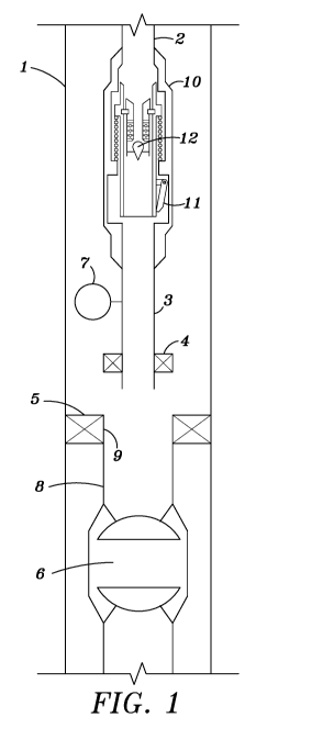
[0055] Figure 1-5 illustrates the various steps that can be taken prior to
opening the barrier valve
of a subsea well according to an embodiment of the invention.
[0056] As shown in Figure 1, a typical subsea well includes casing 1, a
tubular string 2, a stab 3
with an annular seal 4, a polished bore receptacle 8, tubing hangers 5 and a
barrier valve 6. In
accordance with the invention an injection valve 10 with a variable orifice
insert 12 is attached to a
lower end of the tubular string 2. Injection valve 10 includes a flapper
closure element 11. The
flapper element 11 is in an open position and variable orifice insert 12 is in
a bypass mode to allow
the injection valve to be run into the well adjacent to the polished bore
receptacle as shown in
Figure 1.
[0057] Figure 2 illustrates the position of the injection valve with stab 3
positioned within the
polished bore receptacle. Flapper element 11 is in the open position and the
variable orifice insert
12 is in the bypass mode.
[0058] Applying pressure to the barrier valve with the injection valve in the
position and the
relieving the tubing pressure will cause flapper element 11 to close as
illustrated in Figure 3 as
discussed below. In order to pressure test the injection valve and barrier
valve pressure now can be
increase between the two valves via the pressure testing gauge and inlet 7,
and pressure within
tubing 2 is relieved. Once the dual barrier integrity is confirmed, the
blowout preventer assembly
can now be removed from the well head. At this point two pressure cycles have
been completed.
[0059] At this point by increasing tubing pressure the flapper element with
open to the position
shown in Figure 4 and when tubing pressure is relieved, the flapper element
will remain open as
explained below. The variable orifice insert remains open in a bypass
position. Now the barrier
- 5 -
CA 03020881 2018-10-12
WO 2017/180632 PCT/US2017/027023
valve can be pressure cycled as needed with the injection valve and the
variable orifice valve
remaining open.
[0060] Figure 5 illustrates the barrier valve in an open position after the
final barrier valve
pressure cycle. With the barrier valve open initial injection flow resets the
variable orifice insert as
explained below and flow occurs through the barrier valve as shown in Figure
6. When injection
fluid flow stops, flapper element 11 will move to a closed position shown in
Figure 7. The variable
orifice insert and the injection valve will open without flapper damage and
close for protection
when injection stops thereby forming a dual barrier injection valve.
[0061] Figure 8 illustrates the details of an injector valve including a
variable orifice insert
according to an embodiment of the invention.
[0062] Injector valve 15 includes a main valve housing which includes an
uphole connector
portion 20, a piston housing 21 having a vent 17, a middle portion 22 and a
downhole flapper
element housing 23. Flapper element 63 is pivotably mounted by a pivot mount
62 to housing 23 in
a known manner.
[0063] An hydraulic piston 26 is positioned within a wall section of piston
housing 21. The
uphole portion of piston 26 is exposed to pressure within connector portion
20. The downhole
portion of piston 26 abuts against a shoulder 19 on an upper indexing sleeve
24. An upper flow
tube 36 has an uphole portion 25 positioned within upper indexing sleeve 24,
and a lower portion
40 which extends within middle hosing portion 22. Upper flow tube 36 also
includes an enlarged
portion 125. Upper indexing sleeve 24 shown in Figure 9 is mounted for axial
and rotational
movement within the injection valve housing and includes a plurality of
grooves section 70-83 as
depicted in Figure 10. A pin 28 fixed in housing 21 is adapted to guide axial
and rotational
movement of the upper indexing sleeve 24 via groove sections 70-83. An annular
bearing 112 is
positioned between shoulder 19 and upper flow tube 36.
[0064] A variable orifice insert 112 is inserted into the injection vale
housing and includes a
connector portion 29, a locking collet 38 with a plurality of radially spaced
fingers 39 and an upper
flow section 47 which is connected to a lower flow tube 46. At least one
magnet 44 is attached to
lower flow tube 46 and at least one magnet 45 of opposite polarity is freely
mounted on the lower
flow tube. Magnet 45 is adapted to move with a lower flow sleeve 43 which
moves axially over
lower flow tube 46. A spring 51 is positioned between magnet 45 and a stop 102
provided on lower
- 6 -
CA 03020881 2018-10-12
WO 2017/180632 PCT/US2017/027023
flow tube 46 so that axial movement of lower flow sleeve 43 will compress
spring 51. Seals 111
are positioned between upper flow tube 36 and the variable orifice insert 112.
[0065] Lower flow sleeve 43 carries at its downhole end a valve body 53
supported by a
plurality of struts 54. A valve seat 55 is provided on the downhole end of
lower flow tube 46 to
create a variable annular orifice 115 shown in figure 40.
[0066] A lower cylindrical indexing sleeve 103 shown in perspective in figure
11 includes an
uphole portion 105 and a downhole portion 61. Lower indexing sleeve 103 also
include a plurality
of grooves 89-101 on its outer surface as depicted in figure 12. Lower
indexing sleeve is adapted
for rotational and axial movement within the injection valve housing. An
annular power spring 41
surrounds the lower portion 40 of the upper flow tube 36 and the uphole
portion 105 of the lower
indexing sleeve as shown in figure 8. Power spring 41 is captured between
upper flow tube 36 and
a shoulder 104 in the interior of middle housing 22 so that as upper flow tube
is moved in a
downhole direction via piston 26 by pressure within the tubular string, power
spring 41 is
compressed. Downhole movement of section 61 of the lower indexing sleeve is
constrained by a
shoulder 64 pivoted in the interior surface of injection valve housing 22. A
fixed pin 110 guides
movement of lower indexing sleeve 103 via grooves 91-101.
[0067] A plurality of locking dogs 35 cooperate with a groove 37 on the
interior surface of upper
flow tube 36 to lock the variable orifice insert within the injection valve.
In the position shown in
figure 8, lower portion 61 of the lower indexing sleeve holds flapper element
63 in an open
position. A locking collet 42 is located at the lower end of lower portion 40
of the upper flow tube
and is adapted to capture the lower indexing sleeve at groove 49.
[0068] The operation of the variable orifice insert including the run in
position is more fully
described in U.S. Patent Application Publication number 2015/0361763A1
published December
17, 2015, the entire contents of which is hereby expressly incorporated herein
by reference thereto.
[0069] Figure 13 illustrates the condition of the injection valve at its
location in the well shown
in figure 1. In this position flapper element 63 is in an open position, the
variable orifice insert is in
the bypass position, pin 28 of the upper indexing sleeve is within the
downhole end of slot 70 as
shown in figure 14 and pin 110 of the lower indexing sleeve is at the top of
groove 91 as shown in
figure 15.
[0070] Figure 16 illustrates the condition of the injection valve shown in the
position of figure 2
after the tubing pressure against the barrier valve been increased. Pressure
acting on piston 26
- 7 -
CA 03020881 2018-10-12
WO 2017/180632 PCT/US2017/027023
moves the piston in a downhole direction which in turn axially moves upper
indexing sleeve 24,
upper flow tube 36 and variable orifice insert 13 downwardly, thereby
compressing power spring
41. Pin 28 is now located at the top of groove 72 of upper indexing sleeve as
depicted in figure 17
and pin 110 is positioned at the top of groove 91 of the lower indexing sleeve
as shown in figure
18. The variable orifice insert is still in the bypass mode allowing limited
fluid flow through
annular orifice 105. Lower portion 40 of the upper flow tube engages and
captures upper portion
105 of the lower indexing sleeve at 49.
[0071] Figure 19 illustrates the condition of the injection valve as shown in
figure 3 after the
tubing pressure is relieved. Power spring 41 shifts upper flow tube 36, lower
flow tube 40 and the
lower indexing sleeve and variable orifice insert to an uphole portion. This
causes flapper element
63 to close. Pin 28 is now positioned at the bottom of groove 74 of the upper
indexing sleeve and
pin 110 is positioned at 89 of the lower indexing sleeve as shown in figures
20 and 21.
[0072] As pressure within the tubing is increased to do pressure testing, the
piston 26, upper
flow tube 36, upper and lower indexing sleeves well be moved downwardly a
short distance as
shown in figure 22 and as illustrated by the pin 28 being positioned at 76 in
the upper indexing
sleeve as shown in figure 23. Pin 28 thus restricts further downward movement
of upper indexing
sleeve 24. Pin 110 is located at position 89 shown in figure 24. Power spring
41 has been
compressed a limited amount. Flapper valve 63 remains closed.
[0073] At this point pressure within the tubing is relieved so that the
injection valve is now in the
position shown in figure 25. Pressure can be applied between the injection
valve and the barrier
valve through pressure downhole gauge 7 for testing purposes. Any leak rate is
monitored. In this
position flapper element 63 is closed as is barrier valve 6. Pin 28 is
positioned at 77 of the upper
indexing sleeve as shown in figure 26 and pin 110 is located at position 89 of
the lower indexing
sleeve as shown in figure 27. Power spring 41 has moved the piston, upper and
lower indexing
sleeves, the upper flow tube and the variable orifice insert to the position
shown in figure 25. If the
pressure testing is successful, the blowout preventer at the well head may now
be removed.
[0074] At this point in the well completion process, tubing pressure can be
increase and flapper
element 63 will be opened as shown in figure 28 by virtue of piston 26 moving
downhole thereby
axially moving upper indexing sleeve 24, flow tube 36 and lower indexing
sleeve 103. Lower
portion 61 of the lower indexing sleeve 13 will pivot flapper element 63 to an
open position.
- 8 -
CA 03020881 2018-10-12
WO 2017/180632 PCT/US2017/027023
[0075] In this state of operation, pin 28 will be at location 80 of the upper
indexing sleeve as
shown in figure 29 and pin 110 will be at location 95 of the lower indexing
sleeve as shown in
figure 30.
[0076] At this point pressure within the tubing can be relieved and the
injection valve will revert
back to the condition of figure 31. Power spring acts on upper flow tube 36,
upper indexing sleeve
24 and piston 26 to move them to the position shown in figure 31. Pin 28 is
positioned at location
82 of the upper indexing sleeve as shown in Figure 32 and pin 110 of the lower
indexing sleeve is
at position 97 as shown in Figure 33.
[0077] As pressure cycles are applied to the injection valve, in the condition
of Figure 31 as
required to open the barrier valve, upper indexing sleeve's axial movement is
limited by end points
81 and 82 as shown in figure 35 which limits the movement of piston 26.
Consequently flapper
element 63 remains in an open position as shown in Figure 34. Pin 110 is
located at position 97 of
the lower indexing sleeve as shown in figure 36.
[0078] When the barrier valves is opened and flow occurs, piston 28, upper
indexing sleeve 24
and upper flow tube 36 will be returned to position shown in figure 37. Pin 28
is at position 82 of
the upper indexing sleeve as shown in figure 38 and pin 110 remains at
position 97 of the lower
indexing sleeve as shown in figure 39.
[0079] Full flow is now possible through the injection valve and the barrier
as shown in figure
40. Flapper element 63 has been moved to a fully open position by lower
portion 61 of the lower
indexing sleeve and valve body 53 has been axially displaced from valve seat
55 by the full flow
thereby creating annular orifice 105. Spring 51 is compressed by axially
movement of lower flow
sleeve 43. The force of the full flow through the injection valve is
sufficient to overcome the
attractive force between magnets 44 and 45 and the force necessary to compress
spring 51. Power
spring 41 is also compressed by the force of injection fluid acting on upper
flow tube at 36.
Downhole movement of upper indexing sleeve 24 is prohibited by pin 28 engaging
the top portion
81 of the groove in the outer surface of upper indexing sleeve 24 as shown in
figure 41. Lower
indexing sleeve has moved in a downhole direction to a point where further
movement is blocked
by pin 110 engaging the groove on the outer surface of the lower indexing
sleeve at 100, as shown
in figure 42.
[0080] Stopping the flow of injection fluid will result in the injection valve
moving to the
condition shown in figure 43. Power spring 41 shifts upper flow tube 36 in an
uphole direction and
- 9 -
CA 03020881 2018-10-12
WO 2017/180632 PCT/US2017/027023
upper flow tube 36 through locking collet 42 in groove 49 of the lower
indexing sleeve carriers
with it lower portion 61 of the lower indexing sleeve 103 to the position
shown in figure 43.
Flapper 63 is resiliently biased to a closed position as is well known in the
art and thus will pivot to
engage valve seat 111 thus preventing uphole fluid flow.
[0081] Spring 51 and magnets 44, 45 will move lower flow sleeve 43 and valve
body 53 in an
uphole direction to engage valve seat 55 thereby forming a second valve which
prevents uphole
fluid flow. Thus a dual barrier safety valve is formed.
[0082] Pin 28 is located at position 82 of the upper indexing sleeve as shown
in Figure 44 and
pin 110 is positioned at point 101 in the lower indexing sleeve as shown in
figure 45.
[0083] If injection fluid flow is restarted, the injection valve will assume
the full flow condition
shown in figure 40 with the travel of the upper indexing sleeve limited by the
distance between
points 81 and 82 as shown in figure 41 and lower flow tube can move axially
between point 100
and 101 as shown in figure 45. In this manner, injection fluid flow may be
started and stopped an
unlimited number of times. Once the drilling blow out preventer is removed, a
production tree is
installed on the well. The barrier valve can now be cycled permanently open
thereby activating the
injection valve. When this occurs, dual barriers are maintained by the
injection valve and the
production tree.
[0084] The spring constants for springs 41 and 51 are chosen such that upper
flow tube 36 will
move to open the flapper valve at a first pressure level and an increased flow
pressure will open the
variable annular orifice 115.
[0085] Although the present invention and its advantages have been described
in detail, it should
be understood that various changes, substitutions and alterations may be made
herein without
departing from the spirit and scope of the invention as defined by the
appended claims.
- 10 -