Note: Descriptions are shown in the official language in which they were submitted.
CA 03021020 2018-10-12
WO 2017/184916 PCT/US2017/028723
BEVERAGE CAN HAVING A GROMMET
TECHNICAL FIELD
[0001] The present invention relates to containers, and more particularly to
pressurized
beverage containers having a valve.
BACKGROUND
[0002] Commercial beverage cans are typically formed of two pieces: a drawn
and
wall-ironed ("DWI") body and an end or lid seamed onto the open end of the can
body. In the
DWI process for forming a can body, a circular blank is first cut from a sheet
of a 3000 series
aluminum alloy, such as 3004 having the following properties according to
(ASTM B209-14):
Aluminium: 95.6 to 98.2% (or remainder after the limits below)
Copper: 0.25% max
Iron: 0.7% max
Magnesium: 0.8 to 1.3%
Manganese: 1.0 to 1.5%
Silicon: 0.3% max
Zinc: 0.25% max
Residuals: 0.15% max
[0003] The blank is drawn into a cup in a machine referred to as a cupper. The
drawing
process typically does not change the thickness of the material, such that the
sidewall and base of
the cup have the same or nearly the same thickness as the blank.
[0004] The cup is then transferred into a machine referred to as a bodymaker,
in which
a cylindrical ram is inserted into the open end of the cup in a close fit. The
ram them pushes the
cup through a series of circular dies. Each die has an opening diameter that
is slightly less than
the outside diameter of the metal of the cup. Thus the metal is "ironed" in
each die, which thins
and elongates the sidewall. At or near the end of the ironing stages, the ram
pushes the can body
onto doming tooling, which deforms the flat can bottom into a dome and forms
the foot. The
most popular size of commercial beverage cans have a dome having a thickness
of
approximately 0.010 inches thick. In most circumstances, the bottom of the can
is structurally
complete at the end of the bodymaking operation.
[0005] After the bodymaker, the can body typically goes through operations
that form a
neck and a flange on the open end of the can. The can body before filling with
the product is
- 1 -
CA 03021020 2018-10-12
WO 2017/184916 PCT/US2017/028723
coated with a conventional lacquer to provide a barrier between the liquid
product and the
aluminum.
[0006] The end or lid is typically formed of a 5000 series aluminum alloy in a
shell
press that forms a circular blank into a shell and a conversion press that
attaches the tab to the
shell. After filling, an end is positioned on the can body such that the
peripheral curl structure of
the end is aligned with the can body flange. The both the end and the can body
are mutually
deformed to form the seam.
[0007] The internal pressure in a beverage can typically is from gas entrained
in the
liquid product, or generated from liquid nitrogen dosing prior to seaming the
container.
[0008] It has been a longstanding focus of DWI beverage can manufacturers to
make
the can lightweight and structurally intact, even when the can is under
pressure and is given
rough handling.
[0009] Aerosol cans typically are made of three pieces: a domed end that is
fitted with
a dispensing valve, a cylindrical body that is open on each end, and a shallow
bottom end. The
can body is typically formed by rolling a flat sheet of tinplate steel and
welding the ends together
to form a longitudinal joint. The bottom end and domed ends are seamed onto
the open ends of
the welded cylinder.
[0010] Aerosol cans typically have a valve in the top component of the can,
which is
used for charging the can with propellant. Alternatively a grommet that is
located in an aperture
in the domed base, may be used for charging the can with a propellant, which
typically is a
volatile hydrocarbon. The grommet in the domed base is used when the product
and the
propellant must remain separate. For example, popular commercial systems,
referred to bag-in-
can or bag-on-valve, use a pouch or bag that holds the product while the
propellant surrounds the
bag. Some applications use a piston barrier to separate the product from the
propellant, such as
technology marketed under the tradename EarthsafeTM by a sister company of the
present
assignee.
[0011] Several conventional grommets are commercially available for charging
aerosol
cans with propellant, as will be understood by persons familiar with
technology of charging
aerosol cans. In a conventional aerosol can, an aperture is formed in the
bottom end before the
end is seamed onto the cylindrical can body. Because the aperture is formed in
the unattached
end, opposing tools have easy access to contact the upper and lower surfaces
of the end. The
grommet can then be installed into the aperture from either the topside or
underside of the end
before seaming onto the can body.
- 2 -
CA 03021020 2018-10-12
WO 2017/184916 PCT/US2017/028723
SUMMARY
[0012] In the process of forming an aperture, also referred to as a through-
hole, by a
tool opposing tools puncturing a metal sheet, a burr typically is formed.
[0013] A burr formed on the inboard side of the rim of the aperture may reduce
contact
between the burr and the liquid product (compared with a burr located on the
outboard side of
the aperture rim), as the burr may be in contact with or buried in the
elastomer or polymer of the
grommet. The burr may be uncoated or have less coating than the topside of the
domed base,
and therefore contact between the burr and the liquid product has the
possibility of having a
detrimental effect on the product.
[0014] According to an aspect of the invention, a filled and sealed beverage
can, an
unseamed can body, and a method for forming a valve/grommet in a can body are
provided. The
filled and sealed beverage can includes the drawn and wall ironed can body
that includes a dome
in the base, a foot outboard the base, and an elongate ironed sidewall
extending upwardly from
the foot. The dome has an aperture formed through the dome and a wall about
the aperture that
terminates in a rim. A burr is located on an inboard portion of the rim. A
grommet is disposed
in the aperture. An inboard portion of the aperture is in contact with the
liquid product contents
of the can. The beverage can also includes an end seamed to an open end of the
can body
opposite the base to enclose the can.
[0015] In a preferred embodiment, the wall is an upstanding wall that is
vertical or
nearly vertical and is circumferential about the aperture. The dome may be
recess-less about the
upstanding wall such that the base of the grommet is not recessed relative to
the dome, or may
dome may have a recess (such as about the aperture and/or wall) such that the
base of the
grommet is recessed relative to the dome.
[0016] Preferably, the upstanding wall terminates at a rim surface that forms
an angle A
relative to a horizontal reference line that is between -30 degrees and 60
degrees, preferably
between zero and 45 degrees, and more preferably between 5 and 40 degrees.
[0017] As the burr is on the inboard side, the burr may contact the grommet.
The
grommet includes a base located on the outboard side of the dome, a crown
located on the
inboard side of the dome, and a neck between the base and the dome for
receiving the rim of the
aperture. Thus, in a preferred embodiment the burr contacts the neck of the
grommet when the
grommet is in its sealing state. Because the dome of the grommet is in the
interior of the can, a
portion of the grommet contacts the liquid product.
[0018] The method of forming a valve in a drawn and ironed beverage can body
begins
with a one-piece, drawn and ironed beverage can body that includes a dome in
the base, a foot
- 3 -
CA 03021020 2018-10-12
WO 2017/184916 PCT/US2017/028723
outboard of the base, and an elongate ironed sidewall extending upwardly from
the foot. The
method includes the steps of positioning a first tool in an interior of the
can body; contacting an
exterior surface of the dome with a second tool such that the first and second
tools are aligned;
forming an aperture in the dome by the action of the first and second tools
such that a burr is
formed on a inboard rim of the aperture; and inserting a grommet into the
aperture. The first tool
contacts an interior surface of the dome. And the burr is inwardly oriented
relative to the
grommet.
[0019] The forming step preferably includes (or the method includes another
step of)
deforming a portion of the dome adjacent the aperture to form an upstanding
wall. Preferably
the deforming step occurs at the same time as the forming step and before the
inserting step.
Preferably, the upstanding wall is vertical or nearly vertical and is
circumferential about the
aperture.
[0020] The dome may be recess-less about the upstanding wall such that the
base of the
grommet is not recessed relative to the dome, or the dome may has a recess, as
the result of any
of the method steps, about the upstanding wall such that the base of the
grommet is recessed
relative to the dome.
[0021] Preferably, the upstanding wall is formed such that the upstanding wall
terminates at a rim surface that forms an angle A relative to a horizontal
reference line that is
between -30 degrees and 60 degrees, preferably between zero and 45 degrees,
and more
preferably between 5 and 40 degrees.
[0022] As the burr is on the inboard side, the burr may contact the grommet
when
assembled. The grommet includes a base located on the outboard side of the
dome, a crown
located on the inboard side of the dome, and a neck between the base and the
dome for receiving
the rim of the aperture. Thus, in a preferred embodiment the burr contacts the
neck of the
grommet when the grommet is in its sealing state. Because the dome of the
grommet is in the
interior of the can, a portion of the grommet contacts the liquid product.
BRIEF DESCRIPTION OF THE DRAWINGS
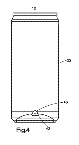
[0023] Figure 1 is a side view of a beverage can assembly according to an
aspect of the
present invention.
[0024] Figure 2 is a top perspective view of the beverage can assembly of
Figure 1,
with the end removed for clarity.
[0025] Figure 3 is a bottom perspective view of the beverage can assembly of
Figure 1.
- 4 -
CA 03021020 2018-10-12
WO 2017/184916
PCT/US2017/028723
[0026] Figure 4 is a longitudinal cross section view bisecting the can
assembly of
Figure 1.
[0027] Figure 5 is a perspective view of the cross section of Figure 4.
[0028] Figure 6 is a top view of the can of Figure 1, with the end of the can
assembly
removed for clarity.
[0029] Figure 7 is bottom view of the can assembly of Figure 1.
[0030] Figure 8 is an enlarged cross sectional view a portion of the dome of
the can of
Figure 1 bisecting the grommet.
[0031] Figure 9 is a cross sectional view bisecting the grommet before
installation into
the aperture.
[0032] Figure 10 is an enlarged cross sectional view of a portion of the
aperture in the
can bottom.
DETAILED DESCRIPTION OF ILLUSTRATIVE EMBODIMENTS
[0033] Referring to the figures, a beverage can assembly 10 includes a can
body 20, an
end, and a grommet 40. In the figures, the can end is omitted for clarity to
illustrate the
grommet.
[0034] The can end, which may be conventional, is seamed onto the end of the
can
body. It is understood that the can end may be, for example, one of the ends
as marketed by
Crown Cork & Seal, Inc. under its SuperEnd mark, such as an end as generally
described in
United States Patent Application Number 102070.006145 ("ISE"), the structural
description of
which is incorporated herein by reference. Accordingly, it is understood that
the end includes a
curl or hook that cooperates with a can body flange to form the seam shown in
the figures, a
center panel, a pour opening defined by a score on the center panel, a tab for
opening the pour
opening upon actuation, and other structure that will be understood by persons
familiar with
beverage can configuration. The present invention is not limited to the
particular end
configuration.
[0035] It is understood that the present invention is employed with a sidewall
that is
formed by wall ironing and bottom that is formed in by a doming operation.
Thus, it is
understood that the present invention encompasses any upper configuration of
the can, such as
DWI metal bottles having necks that taper to a neck finish and that often are
capped with a roll-
on pilfer-proof metal closure, metal cans having small, seamed on ends such as
disclosed in
- 5 -
CA 03021020 2018-10-12
WO 2017/184916 PCT/US2017/028723
United States Patent Application Number 14/773,892, entitled "Necked Beverage
Can Having a
Seamed-On End," sometimes referred to as cattle cans.
[0036] Can body 20 is a drawn and wall-ironed, single-piece body that includes
an
integral sidewall 22, a neck 24 that extends to a seam 26, and a base 30. Base
30 extends from
the lower portion of sidewall 22 and includes a foot 32, inboard of which is a
dome 34. In cross
section, foot 32 includes the curved standing ring on which the can rests, an
inboard wall of the
foot that extends upwardly from the standing ring, and a transition that
merges into the dome 34.
The profile shape of base 30 may be conventional.
[0037] Preferably, can body 20 is a conventional 211 or 66mm can body of the
type
that is sold commercially in the United States as a 12 ounce or 16 ounce can
and in Europe as a
330 ml or 440 ml can. The can body can be any height and diameter, such as 52
mm or 58 mm
diameter marketed as SlimTM or SleekTM cans, or any other DWI beverage can
body diameter.
The can body is formed of a 3000 series aluminum, such as 3004. Sidewall 22
typically is
approximately 0.004 inches thick, or 0.003 inches to 0.006 inches. Dome 34 is
typically
approximately 0.010 inches thick, or 0.008 inches to 0.011 inches.
[0038] An aperture 36 is formed in the base, preferably at the center for
convenience of
forming and charging. Aperture 36 preferably includes a wall 62 that deviates,
in cross sectional
profile, from the curvature of dome 34. To the extent that wall 62 deviates
from the curvature of
the dome local to wall 62, wall 62 is referred to as an upstanding wall.
Preferably, the wall
projects inwardly (that it, inward toward the can or upwardly in the resting
orientation).
Alternatively, the present invention may be employed with a dome for which
there is no wall at
all, either inwardly protruding or outwardly protruding.
[0039] Wall 62 terminates at a rim 64, which defines a rim surface 64 at its
terminal
face. In circumstances in which upstanding wall 62 approaches vertical at rim
64, rim surface 64
will form an angle A that is approaches horizontal. The angle that rim surface
64 (in cross
section) forms relative to a horizontal reference line, as shown best in
Figure 10, encompasses
any angle (other than 90 degrees or nearly 90 degrees ¨ that is, other than
vertical). Preferably,
angle A is between -30 degrees and 60 degrees, more preferably zero and 45
degrees, more
preferably between 5 and 40 degrees. For measuring, a best fit line can be
drawn through rim
surface 64 and projected therefrom.
[0040] As wall 62 is upstanding and/or rim surface angle A is not 90 degrees,
rim 64
has an inboard side and an outboard side, as defined radially relative to the
a vertical centerline
of aperture 36. Inboard side is radially inward relative aperture 36 and
outboard side is radially
- 6 -
CA 03021020 2018-10-12
WO 2017/184916 PCT/US2017/028723
outward relative to aperture 36. When aperture 36 is formed by opposing
tooling, as is common
for forming grommet apertures, a burr is formed at least on one edge of the
rim of the aperture.
[0041] A burr, in general, is a thin projection of metal that extends from an
edge or
rough edge. Burrs are formed as part of metal fabricating steps, such as
forming the through-
hole in a domed base. When used for aerosols, it may be preferable when
forming an aperture
for a grommet to set up the tooling and control it so that the burr is formed
on outboard side of
the rim such that the burr does not contact or dig into the polymer material
of the grommet. The
inventors have found, however, that when employing modern tooling with modern
grommets, a
burr can contact the grommet in a way that does not compromise the function of
the grommet
during and after charging. The burr when formed on the inboard side is thus
not in contact with
or has reduced contact with the liquid product (compared with a burr located
on the outboard
side of the aperture rim), which is beneficial because burrs of apertures
usually lack sufficient
lacquer coating as a barrier against liquid product contact.
[0042] The invention is not limited to any particular grommet. For purposes of
illustration, a grommet marketed as the UltramotiveTM grommet is shown in the
figures and
described. A person familiar with grommet and propellant charging technology
related to
grommets will understand the use of other grommet configurations, such a
universal grommet or
other commercially available grommets.
[0043] Grommet 40 has a base 42, a neck 44, and a crown 46. Neck 16 fits
within the
aperture 36 as shown in the figures, as best illustrated in Figure 8. Figure 9
illustrates grommet
40 before insertion into aperture 36.
[0044] Base 42 has four through openings 48 through which propellant may be
inserted
to charge can 10. Openings 48 extend through base 42 to the extent that at
least a portion of the
openings 48 are in communication with the space about neck 44. During the
charging process, a
pin of a gassing head is applied to the center of grommet 40 to stretch neck
44 and extend crown
46 upwardly to lift crown 46 out of engagement with base 42. Thus, upon
stretching, openings
48 communicate with the interior of can assembly 10 to charge the can with
propellant. Then
when the gassing head is removed, the elastic grommet returns to its at-rest
positions shown in
Figure 8 in which openings 48 are sealed, which is referred to as the
grommet's sealing state.
Grommet 40 also has features that facilitate stretching the neck 16 during the
charging process,
as is understood by persons familiar with grommet structure and function. The
portion of United
States Patent Number 6,729,362 explained the structure of the grommet in its
relaxed state,
sealing state, and charging state is incorporated herein by reference. The
inventors have found
that, contrary to the conventional thinking, even with a burr located on the
inboard side of the
- 7 -
CA 03021020 2018-10-12
WO 2017/184916 PCT/US2017/028723
rim 64 (that is, inwardly facing toward the grommet), the grommet can extend
between its
relaxed state and charging state and back again without interfering in the
charging or sealing
functions of the grommet.
[0045] To form can 10, can body 20 is first formed, preferably by conventional
means.
Aperture 36 is formed by the action of opposing tools contacting the opposing
surfaces (inboard
and outboard) of dome 34. The tooling deforms the dome surface about aperture
36 to thereby
form upstanding wall 62 and rim surface 64. Preferably, there is no recess or
countersink about
upstanding wall 62 to receive or recess grommet base 42. Thus, dome 34
preferably has a
smooth and unbroken curve that extends outwardly from upstanding wall 62. The
grommet 40 is
installed from the bottom of can body 20. After the can is filled with product
and sealed by
seaming an end onto the can body, the can is charged with a gas. The product
may be any
beverage. One example is a coffee product with milk or cream, and the charging
gas is nitrous
oxide.
[0046] The tooling for forming aperture 36, including aperture rim 60,
upstanding wall
62, and rim surface 64 are well known, which will be understood by persons
familiar with
manufacturing of cans having grommets. Preferably, the grommet is installed
from the
underside of can 20, rather than through the open end of the can, for reasons
of access and
alignment. Moreover, persons familiar with grommet technology will understand
tooling
configurations that are capable of forming the burr on the inboard side of rim
surface 64.
[0047] The present invention is described using embodiments that are not
intended to
be limiting. Rather, the claims are intended to define the scope of the
invention.
- 8 -