Note: Descriptions are shown in the official language in which they were submitted.
1
TIRE PRESSURE CONTROL VALVE ASSEMBLY
TECHNICAL FIELD
[0001] This relates to a valve assembly used in a system for controlling
the tire pressure
of a vehicle, and a method of manufacturing the valve assembly.
BACKGROUND
[0002] Tire pressure control systems are used to increase and decrease
the pressure of a
vehicle to improve the vehicle's operation. For example, when travelling on
highways, a
higher tire pressure results in better fuel economy, whereas when traversing
soft ground such
as mud or sand, a vehicle may have better traction at lower tire pressures.
[0003] Various systems are available that allow tire pressure changes to
be automated,
such as United States patent no. 5,587,698 (Genna) entitled "Automatic tire
pressure control
system for a vehicle" which describes a system that automatically adjusts the
pressure in
vehicle tires in respond to air pressure and temperature fluctuations.
SUMMARY
[0004] According to an aspect, there is provided a valve assembly for a
tire pressure
control system used to control tire pressure of a vehicle. The valve assembly
compiises a
unitary body and one or more valves. The valve assembly comprising attachment
points for
mounting the unitary body to a vehicle wheel end, one or more valve cavities
formed in the
unitary body, and a plurality of air passages formed in the unitary body. The
plurality of air
passages comprise an air supply passage for connecting to an air supply and a
tire supply
passage for connecting to a vehicle tire. The air supply passage and the tire
supply passage are
connected to each of the one or more valve cavities. Each of the one or more
valves comprises
a valve element mounted to the valve cavity, an air supply chamber in
communication with the
air supply passage, and a tire supply chamber in communication with the tire
supply passage.
The air supply chamber and the tire supply chamber are defined by the valve
cavity and the
valve element. The valve element is biased toward a closed position that seals
between the air
supply chamber and the tire supply chamber, the valve element moving to an
open position
Date Regue/Date Received 2022-11-25
2
that permits airflow between the air supply chamber and the tire supply
chamber upon
application of a predetermined pressure within the valve cavity against the
valve element.
[0005] According to other aspects, the valve assembly may comprise one
or more of the
following features, alone or in combination: each valve may comprise a cover
that overlies the
valve cavity and the valve element, where an inner surface of the cover
defines a cover cavity;
the valve element may comprise a diaphragm secured between the valve cavity
and the cover
cavity, wherein the diaphragm is exposed to the tire pressure on a valve-
facing side of the
diaphragm and atmospheric pressure on a cover-facing side of the diaphragm;
the diaphragm
.. may be biased by a spring element positioned between the cover and the
diaphragm; the cover
may comprise a vent that vents the cover cavity to atmosphere; the valve
assembly may further
comprise an air supply connector in communication with each of the air supply
passages, where
the air supply connector is rotatable relative to the unitary body, and the
air supply connector
is connected to an air supply hose from an air supply; each air supply passage
may comprise a
flow restriction that restricts the rate of pressure reduction during a
deflation operation through
the valve cavity; each tire supply passage may comprise a supplemental port
for selectively
connecting an alternate air passage from the air supply to the tire supply
passage; and the
attachment points of the valve assembly may comprise a set of apertures sized
and aligned to
receive two or more tire studs of a tire wherein the attachment points may
comprise a plurality
.. of sets of apertures sized to mount to different tire stud patterns.
[0006] According to an aspect, there is provided a method of
manufacturing a valve
assembly. The method compi __ ises the steps of:
obtaining a unitary body having a first face, a second face opposite the first
face
and separated by a thickness;
machining the unitary body to form attachment points for mounting the unitary
body to a vehicle wheel end, and one or more valve cavities formed in the
unitary body, each
of the one or more valve cavities being connected to an air supply passage
that is connectable
to an air supply and a tire supply passage that is connectable to a vehicle
tire, wherein each of
the air supply passage and the tire supply passage are formed in the unitary
body;
mounting a valve element to each of the one or more valves such that the valve
Date Regue/Date Received 2022-11-25
3
element defines an air supply chamber in communication with the air supply
passage and a tire
supply chamber in communication with the tire supply passage; and
biasing the valve element toward a closed position that seals between the air
supply
chamber and the tire supply chamber such that the valve element moves to an
open position
that permits airflow between the air supply chamber and the tire supply
chamber upon
application of a predetermined pressure within the valve cavity against the
valve element.
[0007] According to other aspects, the method may comprise one or more
of the following
features, alone or in combination: mounting a valve element may comprise
mounting a cover
to the unitary body that overlies the valve cavity and the valve element,
wherein an inner
surface of the cover may define a cover cavity, and wherein the valve element
may comprise a
diaphragm secured between the valve cavity and the cover cavity, such that the
diaphragm is
exposed to the tire pressure on a valve-facing side of the diaphragm and
atmospheric pressure
on a cover-facing side of the diaphragm; biasing the valve element may
comprise biasing the
diaphragm by a spring element positioned between the cover and the diaphragm;
the cover
cavity may comprise a vent that is vented to atmosphere; the method may
further comprise the
steps of attaching an air supply connector to the unitary body in
communication with each of
the air supply passages, the air supply connector being rotatable relative to
the unitary body,
and connecting the air supply connector to an air supply hose from an air
supply; machining
the air supply passages may comprise forming a flow restriction that restricts
the rate of
pressure reduction during a deflation operation through the valve cavity;
machining the tire
supply passage may comprise machining a supplemental port in fluid connection
with the tire
supply passage; attachment points may comprise a set of apertures sized and
aligned to receive
two or more tire studs of a tire; and the attachment points may comprise a
plurality of sets of
apertures sized to mount to different wheel end stud patterns.
[0008] In other aspects, the features described above may be combined
together in any
reasonable combination as will be recognized by those skilled in the art.
BRIEF DESCRIPTION OF THE DRAWINGS
[0009] These and other features will become more apparent from the
following description
in which reference is made to the appended drawings, the drawings are for the
purpose of
Date Recue/Date Received 2022-11-25
4
illustration only and are not intended to be in any way limiting, wherein:
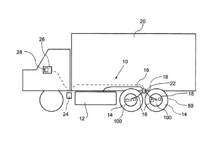
FIG. 1 is a tire pressure control system shown on a vehicle.
FIG. 2 is a perspective, exploded view of the tire pressure control valve
assembly.
FIG. 3 is a partially transparent top plan view of a unitary body of the valve
assembly.
FIG. 4 is a perspective view of a unitary body of the valve assembly.
FIG. 5 is side elevation view in section of the unitary body along line 5-5
shown in
FIG. 3.
FIG. 6 is a detailed top plan view of a valve cavity.
DETAILED DESCRIPTION OF PREFERRED EMBODIMENTS
[0010] Referring to FIG. 1, an example of a tire pressure control
system, generally
identified by reference numeral 10, is shown, with valve assemblies 100
mounted to vehicle
tires 14. In the depicted example, tire pressure control system 10 uses
sensors and a
microcontroller 24 to determine the current tire pressure, and control the
tire pressure
changes when adjusting to a different tire pressure. In some examples, such as
the system
described in Canadian patent application no. 2,970,014 entitled "Tire Pressure
Control
System", microcontroller 24 may use algorithms that allow the system to
effectively learn
how the vehicle air supply 12 and tire groups 50 are configured, and optimize
the inflation
and deflation control of the tires 14, while continually learning these
parameters during
normal operation. The system may also offer the ability to autonomously
control tire
pressures without operator intervention based on data from other sensors. The
discussion
with respect to FIG. 1 relates to a particular system that uses a controller
and automation
intended to improve the efficiency and usability of the system. However, it
will be
understood that this is merely an example of a possible system, and that valve
assemblies
100 may be used in other tire pressure control systems. For example, valve
assemblies 100
may be used in manual systems that rely on manual intervention to increase or
decrease the
tire pressure, where valve assemblies 100 direct the flow of air to or from
tires 14.
[0011] As shown in FIG. 1, one example of a tire pressure control system 10
uses a supply
of compressed air 12 that is connected to supply compressed air to the vehicle
tires 14 through
an air conduit 16, and controlled by a control valve 18. The supply of
compressed air 12 may
Date Regue/Date Received 2022-11-25
5
be any suitable source, such as an existing air supply system that is commonly
found on some
transport vehicles 20 as shown, which typically includes a tank and a
compressor, or may be
an additional or dedicated air supply system installed on the vehicle 20,
which will typically
also include at least a compressor. The conduit 16 and valve assemblies 100
used to connect
between the air supply 12 and the tires 14 may have various configurations
based on the
preferences of the user and the intended use. For example, as will be
discussed below, each
valve assembly 100 may control one tire 14, or a group of tires 14 that are
connected in parallel
downstream of valve assembly 100. In the depicted example, a single control
valve 18 is used
to control inflation and deflation of a group of tires 14 in a double-axle
vehicle 20, where the
wheels are controlled in axle groups 50, where axle group 50 refers to a set
of tires on one side
of vehicle 20. Preferably, as will be discussed below, valve assembly 100 is
designed to
prevent a failure of one tire, such as loss of pressure due to a puncture,
etc., from causing other
tires connected to the same valve assembly 100 to lose pressure as well.
[0012] In the depicted example, the pressure in tires 14 is detected by air
pressure sensors
22, which may be included at any convenient location, such as with valves 18,
valve assembly
100, tires 14, air conduits 16, etc. Valves 18 are controlled by
microcontroller 24 to control
the supply of compressed air to the vehicle tires 14 via valve assemblies 100
to increase the air
pressure in the vehicle tires 14, and to vent compressed air from the vehicle
tires 14 to
atmosphere to decrease the air pressure. If present, microcontroller 24 may be
provided with
different degrees of utility. For example, microcontroller 24 may be
programmed to simply
respond to user inputs, or it may be programmed with instructions to calculate
a valve operation
that may be initiated when a signal is received. Such as signal may originate
from any number
of sources such as an operator interface 26, air pressure sensors 22, or other
sensors 28.
[0013] Referring to FIG. 2, valve assembly 100 is fanned from a unitary
body 102 that has
a first face 103, and a second face 104 opposite to first face 103. Unitary
body 102 has a
thickness that allows various elements, such as passages and cavities
described below, to be
formed. The thickness may not be uniform, and portions may be cut away to
reduce the weight
and amount of material required. Various manufacturing techniques may be used
to form these
elements depending on the material of unitary body 102. In the preferred
embodiment, where
unitary body 102 is made from aluminum due to its cost and material
properties, the elements
Date Regue/Date Received 2022-11-25
6
may be effectively formed by machining. Other materials may be used, such as
steel, nylon,
which may require or permit different manufacturing techniques as is known in
the art.
[0014] Unitary body 102 has one or more valves 120, such as two as shown
in the depicted
example, that are intended to be used for a double-wide tire set. Valve 120
has a valve cavity
106 formed, such as by machining, in first face 103 of unitary body 102, and a
valve element
122. Valve cavity 106 may be described as being integrally formed, in that it
is formed directly
in unitary body 102. Valve cavity 120 may be further defined by other
components installed
within or adjacent thereto, in addition to valve element 122 which is part of
valve 120. Valve
120 has an air supply chamber 108 and tire supply chamber 110, as shown in
FIGS. 3, 4, and
6. As depicted, chambers 108 and 110 are formed within valve cavity 106. Valve
element 122
is biased toward a closed position, such as by a spring element 124. In the
closed position,
valve element forms a seal between air supply chamber 108 and tire supply
chamber 110.
Upon application of a predetermined force within valve cavity 106 against
valve element 122,
valve element 122 will move toward an open position, allowing airflow between
supply
chamber 108 and tire supply chamber 110. Preferably, the predetermined force
required to
open valve element 122 corresponds with a pressure threshold within chambers
108 and 110,
where the force relates to the pressure and the surface area exposed to that
area, as will be
discussed in greater detail below. In the depicted example, valve element 122
is a sealing
diaphragm that sits over valve cavity 106, and is sealed along it outer edge.
As a diaphragm,
valve element 122 moves toward valve cavity 106, and seals between chambers
108 and 110
by engaging a profile that separates the chambers. Valve element 122 as shown
has a spring
element 124 positioned behind valve element 122 to bias valve element 122
toward the closed
position. It has been found that this type of valve provides a sufficiently
reliable and simple
design for the intended purpose. However, it will be understood that there are
various designs
that may be used for valve closure and various ways in which the valve closure
may be biased.
[0015] The depicted example has a valve cover 126 that is fastened
overtop of valve
element 122 and valve cavity 106. Valve cover 126 has a cover cavity 128 that
receives some
or all of valve element 122. When installed, valve cover 126 secures valve
element 122 relative
to valve cavity 106, and provides support for spring element 124. It will be
understood that
other design options are available. For example, valve cover 126 may depend on
the type of
Date Regue/Date Received 2022-11-25
7
valve element 122, the way in which valve element 122 is biased, the type of
spring element
124 if present, etc. Preferably, and as depicted, valve element 122 will be
exposed to air
pressure on one side and atmospheric air on the other side. As depicted, this
is accomplished
by providing valve cover 126 with a vent, such as an orifice 130 that allows
cover cavity 128
to be vented to atmosphere, such that the cover-facing side of valve element
122 maintained at
atmospheric pressure and the valve facing side of valve element 122 is exposed
to the tire
pressure.
[0016] In addition to valve cavities 106, air supply passages 112 and
tire supply passages
114 are founed in unitary body 102. Referring to FIGS. 2 and 3, air supply
passages 112 are
used to connect between air supply chamber 108 and air supply 12 via supply
hoses 118. As
air supply 12 is stationary relative to vehicle 20, and rotates relative to
tires 14, including the
valve stem (not shown), it is necessary to provide a rotating part. As
depicted, this is done by
providing an air supply connector 116 that capable of rotating relative to
unitary body 102.
This allows air supply passage 112 and air supply 12 to be connected, while
still allowing for
relative rotation of the various components. Air supply connector 116 will
generally have a
bearing and seal assembly (not shown) that permits rotation, while maintaining
air pressure
within air supply passage 112. As can be seen, air supply connector 116 is
able to rotate at the
point at which it attaches to unitary body 102. It will be understood that any
suitable assembly
may be used for this purpose, and that the point at which rotation occurs may
vary.
[0017] Air supply connector 116, shown in FIG. 2, is preferably in
communication with
each air supply passage 112 in unitary body 102 as shown in FIG. 3, and has a
connection 118
to air supply hose 16, which is shown in FIG. 1. Referring to FIG. 1, air
supply hose 16 is in
turn connected to air supply 12 via valve 18. Referring to FIG. 3, each air
supply passage 112
may include a flow restriction 113 to restrict the rate of air flow through
air supply passage.
When used, flow restriction 113 is preferably designed and sized to maintain a
predetermined
pressure profile within valve 120, shown in FIG. 2, to maintain valve 120 in
the open position.
Under normal operation, this controls the rate of change of pressure within
valve 120 such that
.. valve 120 is maintained in the open position throughout the operation, even
though the pressure
at control valve 18 (shown in FIG. 1) may be much higher or lower than the
instantaneous
pressure within tire 14. On the other hand, in the event of a failure in the
system, such as a
Date Regue/Date Received 2022-11-25
8
punctured tire or ruptured air hose, the pressure within valve 120 will drop
quickly due to air
escaping through tire supply passage 114. The rapid drop in pressure toward
atmospheric
pressure, once it exceeds the designed threshold, will cause valve 120 to
close, and isolating
the failed tire 14 to prevent air pressure from being lost elsewhere in the
rest of the tire system.
For example, when valve assembly 100 is connected to multiple separate tires
14, a loss in
pressure in one tire 14 would otherwise result in a loss of pressure in all
tires connected in
series.
[0018] As noted above, air supply passages 112 for separate tires 14
that are formed in the
same unitary body 102 may be connected in parallel, allowing a single air
supply 12 and control
valve 18 to control the air pressure in axle group 50 simultaneously. When
sufficient pressure
is in the system, valve elements 122 will be in the open position and will not
restrict the flow
to the respective tires 14. This also allows air to pass between different
tires 14 connected to
the same valve assembly 100. Connected tires 14 will automatically balance
pressure in
.. response to external stimuli that may compress tires 14 within axle group
50 unequally, such
as uneven ground, obstacles, etc. without the intervention of microcontroller
24.
[0019] Tire supply passages 114 form a fluid connection between tire
supply chambers
110 and vehicle tires 14. A cross-section along line 5 in FIG. 3 is shown in
FIG. 5 showing tire
supply passage 114 and valve cavity 106. Tire supply passage may additionally
include a
supplemental valve 115, such as a typical Schrader valve, so that an air
supply may be
connected directly to tire 14, bypassing valve 120. Supplemental valve 115 can
be used to fill
or empty tire 14 when the pressure is below the threshold and valve element
122 is closed, or
to provide a point at which the pressure of tire 14 can be manually tested. In
the depicted
example, both air supply passages 112 and tire supply passages 114 are shown
to extend to the
perimeter of unitary body 102 between first face 103 and second face 104. This
is for ease of
manufacturing supply passages and during normal operation will be sealed with
sealing caps
119. Passages 112 and 114 may take other forms, depending on the preferences
of the user,
the manufacturing techniques used, and the material of unitary body 102
[0020] Unitary body 102 has attachment points 132 that allow valve
assembly 100 to be
mounted to a wheel end 15 of vehicle 20. Wheel end 15 is used to refer
generally to the
Date Regue/Date Received 2022-11-25
9
structural component at the end of a vehicle axle, such as the rim, wheel
assembly, axle end,
etc. In one example, unitary body 102 may be mounted studs that are typically
carried by, for
example, the brake drum or brake disk of wheel end 15. It will be understood,
however, that
unitary body 102 may be mounted to any suitable structural component of wheel
end 15. As
shown, attachment points 132 are preferably a set of apertures sized and
aligned to receive two
or more studs (not shown) of tire 14, which allows valve assembly 100 to be
mounted using
similar equipment and tools to those used to install tires 14. Attachment
points 132 may also
consist of a plurality of sets of apertures that correspond to different stud
patterns, as depicted
in the current example. As shown, unitary body 102 has eighteen attachment
points 132,
permitting unitary body to be mounted to 9 different stud patterns. The number
of attachment
points 132 may be modified according to the preferences of the user, and the
dimensions of
unitary body 102.
[0021] There will now be described a method for manufacturing one
example of a valve
.. assembly 100. The method of manufacturing any given design may be modified
based on the
material being used, and using different manufacturing techniques. It will be
also understood
that the method may be modified to accommodate variations in the design
permitted herein.
[0022] The method begins with obtaining a generally circular unitary
body 102 with flat
first and second faces 103 and 104. Initially, unitary body 102 may be a
"blank", meaning it is
a solid piece of metal cut into a squat, cylindrical shape. Unitary body 102
is then machined
to have various elements, such as attachment points 132, one or more valve
cavities 106, and
a plurality of air passages. Attachment points 132 may be a set or a plurality
of sets of apertures
as described above. Air passages 112 and 114 are machined to be connected to
the valve cavity
.. 106, with air supply passages 112 in communication with valve 18 and tire
supply passages
114 in communication with fires 14. A central aperture is preferably machined
into unitary
body 102 to be fitted with a bearing and valve assembly (not shown) that
allows air supply
passages 112 to be connected to valve 18 via air supply connector 116, which
is capable of
rotating relative to unitary body 102 while being connected to air supply 12
with air supply
hoses 16. Flow restriction 113 may be machined as part of air supply passage
112. A
supplemental port, to which valve 115 is connected, may be machined as part of
tire supply
passage 114. This allows the user to have the option of bypassing valves 120,
such as for rapid
Date Regue/Date Received 2022-11-25
10
inflation or deflation of tires 14, in the event of a failure of valves 120 or
other component, or
to provide a point at which the pressure of tire 14 may be tested.
[0023] Once
the machining steps are completed, a valve element 122 is mounted to each
of the valve cavities 106, such that an air supply chamber 108 in
communication with air supply
passage 112 and tire supply chamber 110 in communication with tire supply
passage 114 are
defined within valve cavity 106. Valve element 122 is biased toward a closed
position that
seals between air supply chamber 108 and the tire supply chamber 110 such that
the valve
element 122 moves to an open position upon the application of a predeten-nined
pressure from
within valve cavity 106 against valve element 122. This will normally be the
range of expected
operating pressures for tires 14. Valve element 122 may be a diaphragm, and
there may be a
cover 126 with a cover cavity 128 secured over top of valve element 122 such
that the
diaphragm is secured between valve cavity 106 and cover cavity 128 and is
exposed to the tire
pressure on the valve-facing side of the diaphragm and atmospheric pressure on
the cover-
facing side of the diaphragm. This may be done by providing a vent, such as a
small orifice or
other opening in cover 126, to maintain atmospheric pressure behind the
diaphragm. Valve
element 122 may be biased with the use of spring element 124 positioned
between cover 126
and diaphragm.
[0024] In this patent document, the word "comprising" is used in its non-
limiting sense to
mean that items following the word are included, but items not specifically
mentioned are not
excluded. A reference to an element by the indefinite article "a" does not
exclude the
possibility that more than one of the elements is present, unless the context
clearly requires that
there be one and only one of the elements.
[0025] The
scope of the following claims should not be limited by the preferred
embodiments set forth in the examples above and in the drawings, but should be
given the
broadest interpretation consistent with the description as a whole.
Date Regue/Date Received 2022-11-25