Note: Descriptions are shown in the official language in which they were submitted.
UV DISINFECTANT SYSTEM
TECHNOLOGY
[0001] The present disclosure relates to disinfectant systems and control and
monitoring of
disinfectant systems.
BACKGROUND
[0002] UV radiation may be used to disinfect clear or opaque liquids such as
water,
including wastewater, juices, brines, marinades, beverages, and the like.
Examples
include U.S. Patent Nos. 3,527,940 and 4,968,891 and U.S. Patent Application
No.
10/542,793. Using UV radiation to disinfect liquids offers many advantages
that often
make it a very attractive option as compared to other methods of disinfecting
liquids.
It will often provide for improved disinfection in a fast, simple, relatively
inexpensive
manner.
[0003] The effectiveness of UV radiation to disinfect a liquid diminishes
rapidly with the
distance that the radiation must pass through the liquid, so the surface of
the liquid
receives stronger radiation than the depths of the liquid. So under conditions
of laminar
flow, disinfection of the deeper liquid is less than disinfection of the
surface of the liquid.
Furthermore, relying primarily upon natural turbulence in a liquid to provide
for even,
thorough disinfection of the liquid can be unreliable.
1
Date Recue/Date Received 2020-06-05
CA 03021376 2018-10-17
WO 2017/188915
PCT/US2016/029114
SUMMARY
100041 In one embodiment, a UV disinfectant system comprises a chamber and a
plurality of
ultraviolet light emitting bulbs. The chamber may have at least one wall
transparent to
ultraviolet light and define a treatment flow path for liquid to be treated
with the ultraviolet light.
The plurality of ultraviolet light emitting bulbs may be positioned external
to the chamber,
adjacent to the transparent wall to direct ultraviolet light into the chamber
along the treatment
flow path. The system may further include an inflow port, outflow port, and
pump. The inflow
port may be configured for passage of the liquid to be treated into the
treatment flow path. The
outflow port may be configured for passage of the treated liquid from the
treatment flow path to
an outlet of the chamber. The pump may be configured for pumping the liquid
through the
chamber. The system may further include a static mixer positioned in the
chamber and
comprising a plurality of vanes extending into the treatment flow path,
dimensioned to disrupt
laminar flow along the treatment flow path. The treatment flow path may
include a gap passing
between at least one of the vanes and the transparent wall. The system may
further include a
cabinet housing the chamber and bulbs and having an upper end and a lower end.
A first blower
may be positioned to drive airflow out of the cabinet at the lower end. A
second blower may be
positioned to drive airflow out of the cabinet at the upper end. A vent may
enable airflow into
the cabinet between the upper end and the lower end of the cabinet. An air
temperature sensor
may be configured to measure air temperature at one or more locations within
the cabinet. A
liquid temperature sensor may be configured to measure a liquid temperature at
one Or more
locations within the chamber. A flow meter may be configured to measure a flow
rate of liquid
at one or more locations within the chamber. The system may further include a
controller
operable to control operations of the pump, bulbs, and blowers and
operationally coupled to the
2
CA 03021376 2018-10-17
WO 2017/188915
PCT/US2016/029114
air temperature sensor, liquid temperature sensor, and flow meter to receive
collected
measurement data, The controller comprises a processor, a computer-readable
storage medium
having instructions stored executable by the processor to perform the
operations of the UV
disinfectant system, and a user interface operable to interface users with the
controller to view
measurement data collected from the air temperature sensor, liquid temperature
sensor, and flow
meter and to modify at least one of power delivery to the bulbs, blower speed,
or pump speed.
100051 In another aspect, a UV disinfectant system comprises a chamber and a
plurality of
ultraviolet light emitting bulbs. The chamber may have at least one wall
transparent to
ultraviolet light and defining a treatment flow path for liquid to be treated
with the ultraviolet
light. The plurality of ultraviolet light emitting bulbs may be positioned
external to the chamber,
adjacent to the transparent wall to direct ultraviolet light into the chamber
along the treatment
flow path. The system may further include an inflow port, outflow port, and
pump. The inflow
port may be configured for passage the liquid to be treated into the treatment
flow path. The
outflow port may be configured for passage the treated liquid from the
treatment flow path to an
outlet of the chamber. The pump may be configured for pumping the liquid
through the
chamber. The system may further include a static mixer positioned in the
chamber and
comprising a plurality of vanes extending into the treatment flow path,
dimensioned to impede
laminar flow along the treatment flow path. The treatment flow path may
include a gap passing
between at least one of the vanes and the transparent wall.
[00061 In one embodiment, the chamber is defined between an outer wall Of an
inner tube and an
inner wall of an outer tube, and wherein the outer tube comprises the
transparent wall. The
vanes may extend from the outer wall of the inner tube. The gap may be defined
between the
vanes and the inner wall of the outer tube. The vanes may spiral around a
circumference of the
3
CA 03021376 2018-10-17
WO 2017/188915
PCT/US2016/029114
inner tube. In one configuration, the vanes do not extend completely around a
circumference of
the inner tube. At least one vane may extend around the eireumference of the
inner tube between
about 160 degrees and about 200 degrees. The vanes may be aligned along the
length of the
treatment flow path. The vanes may be spaced apart between about two feet and
about three
feet along the treatment flow path. Turbulence features may be located on a
surface of at least
one of the vanes to increase local turbulence. The turbulence features may
comprise raised
bumps along an interface of the inner tube and the vane. In still another
aspect, a UV
disinfectant system comprises a chamber and a plurality of ultraviolet light
emitting bulbs. The
chamber may have at least one wall transparent to ultraviolet light and
defining a treatment flow
path for liquid to be treated with the ultraviolet light. The plurality of
ultraviolet light emitting
bulbs may be positioned external to the chamber, adjacent to the transparent
wall to direct
ultraviolet light into the chamber along the treatment flow path. The system
may further include
an inflow port, outflow port, and pump. The inflow port may be configured for
passage the
liquid to be treated into the treatment flow path. The outflow port may be
configured for passage
the treated liquid from the treatment flow path to an outlet of the chamber.
The pump may be
configured for pumping the liquid through the chamber. The system may further
include a static
mixer positioned in the chamber and comprising a plurality of vanes extending
into the treatment
flow path, dimensioned to impede laminar flow along the treatment flow path.
The system may
further include a cabinet housing the chamber and bulbs and having an upper
end and a lower
end. A first blower may be positioned to drive airflow out of the cabinet at
the lower end. A
set.:ond blower may be positioned to drive airflow out of the cabinet at the
upper end. A vent
may enable airflow into the cabinet between the upper end and the lower end of
the cabinet.
4
CA 03021376 2018-10-17
WO 2017/188915
PCT/1JS2016/029114
100071 The first blower and the second blower may be variable speed blowers.
The system may
further comprise a temperature sensor to measure an air temperature in the
cabinet. The first
blower and second blower may be operationally coupled to the temperatures
sensor such that the
speed of the first blower and the second blower increase in response to a
measured temperature
above a set point temperature. The first blower and second blower may be
operationally coupled
to the temperatures sensor such that the speed of the first blower and the
second blower decrease
in response to a measured temperature below a set point temperature. The
temperature sensor
may comprise a thermocouple. The first blower may be located in. the lower end
of the cabinet
and the second blower may be located in the upper end of the cabinet. The
first blower may be
positioned to drive airflow out of the cabinet at the lower end in a first
direction and the second
blower may be positioned to drive airflow out of the cabinet at the upper end
in a second
direction, and wherein the first direction is opposite the first direction The
vent may comprise a
plurality of louvers.
100081 In yet another aspect, .a UV disinfectant system comprises a chamber
and a plurality of
ultraviolet light emitting bulbs. The chamber may have at least one wall
transparent to
ultraviolet light and defining a treatment flow path for liquid to be treated
with the ultraviolet
light The plurality of ultraviolet light emitting bulbs may be positioned
external to the chamber,
adjacent to the transparent wall to direct ultraviolet light into the chamber
along the treatment
flow path. The system may further include an inflow port, outflow port, and
pump. The inflow
Port may be configured for passage the liquid to be treated into the treatment
flow path. The
outflow port may be configured for passage the treated liquid from the
treatment flow path to an
outlet of the chamber. The pump may be configured for pumping the liquid
through the
chamber. The system may further include a static mixer positioned in the
chamber and
CA 03021376 2018-10-17
WO 2017/188915
PCT/US2016/029114
comprising a plurality of vanes extending into the treatment flow path,
dimensioned to impede
laminar flow along the treatment flow path The system may further include a
cabinet housing
the chamber and bulbs.
100091 An air temperature sensor may be configured to measure air temperature
at one or more
locations within the cabinet A liquid temperature sensor may be configured to
measure a liquid
temperature at one or more locations within the chamber-. A flow meter may be
configured to
measure a flow rate of liquid at one or more locations within the chamber. The
system may
flintier include a. controller operable to control operations of the pump,
bulbs, and blowers and
operationally coupled to the air temperature sensor, liquid temperature
sensor, and flow meter to
receive collected measurement data. The controller comprises a processor, a
computer-readable
storage medium having instructions stored executable by the processor to
perform the operations
of the UV disinfectant system, and a user interface operable to interface
users with the controller
to view measurement data collected from the air temperature sensor, liquid
temperature sensor,
and flow meter and to modify at least one of power delivery to the bulbs,
blower speed, or pump
speed.
100101 In one embodiment, the instructions stored in the computer readable
medium comprise a
plurality of set point conditions defining preferred operational conditions
comprising at least one
of (a) an air temperature at the one or more locations in the cabinet, (b) a
liquid temperature at
the one or more locations within the chamber, (c) a flow rate at the one or
more locations within
the chamber, or (d) an illumination of the bulbs. The instructions stored in
the computer-
readable medium mat further include instructions to modify an operation of the
UV disinfectant
system in response to a non-conforming set point condition. The computer-
readable storage
medium may include additional instructions stored to modify an operation of
the UV disinfectant
6
CA 03021376 2018-10-17
WO 2017/188915
PCT/US2016/029114
system in response to a non-conforming set point condition which result in the
operations
comprising terminating power to the bulbs when at least one of (a) the flow
meter measures no
flow, (b) the air temperature sensor measures an air temperature higher than
an air temperature
set point, (c) the liquid temperature sensor measures a liquid temperature
higher than a liquid
temperature set point, or (d) the air temperature sensor measures an air
temperature lower than an
air temperature set point. The computer-readable storage medium may include
additional
instructions stored to modify an operation of the UV disinfectant system in
response to a non-
conforming set point condition which result in the operations comprising at
least one of
terminating power to pump or reducing pump speed when the liquid temperature
sensor
measures a liquid temperature below a liquid temperature set point, Of
supplying power to the
pump or increasing speed of the pump when the liquid temperature sensor
measures a liquid
temperature above a liquid temperature set point. The computer-readable
storage medium may
store additional instructions stored to modify an operation of the UV
disinfectant system in
response to a non-conforming set point condition which result in the
operations comprising
supplying power to the blowers or increasing speed of the blowers when the air
temperature
sensor measures an air temperature above an air temperature set point. In one
embodiment, the
system further comprises a control panel associated with the cabinet, wherein
the user interface
comprises a local user interface provided on the control panel. The user
interface may comprise
a remote user interface accessible to a remote user device over a network,
14herein the remote
user interface is accessible by the remote user device to view measurement
data, and wherein the
remote user interface is operable by the remote user device to control an
operation of the UV
disinfectant system comprising at least one of (a) modifying power delivery to
the bulbs to turn
on Or turn off the bulbs, (b) changing a speed of operation of the pump to
modify a flow rate or
7
temperature of the liquid pumped through the chamber, or (c) changing a speed
of one or
more blowers to modify air temperature at one or more locations within the
cabinet. The
computer-readable storage medium may store additional instructions which when
executed by
the processor keeps track of an operational life of the bulbs.
[0011] Embodiments of the present invention may be adapted for use with
systems to apply
antimicrobial solution to food items, for example, raw chicken, to disinfect
the antimicrobial
solution before it is recycled for reuse within the application system.
Examples of aspects of
such antimicrobial application systems are found in, for example, US patent
applications
10/535,030; 14/471,846; 14/510,385; and 14/510,439.
BRIEF DESCRIPTION OF THE DRAWINGS
[0012] The above brief description, as well as further objects, features and
advantages will be
more fully appreciated by reference to the following detailed description
taken in conjunction
with the accompanying drawings, wherein:
[0013] FIG. 1 is a sectional, side elevation view of a treatment chamber
forming part of a
radiation treatment device for use in a UV disinfectant system according to
various
embodiments;
[0014] FIG. 2 is a sectional, overhead view of a radiation treatment device
for use in a UV
disinfectant system according to various embodiments;
8
Date Recue/Date Received 2020-06-05
CA 03021376 2018-10-17
WO 2017/188915
PCT/US2016/029114
100151 FIG. 3 is a partial, side elevation view of an alternate embodiment of
a radiation
treatment device for use in a UV disinfectant system according to various
embodiments;
10016] FIG. 4 is a is a partial, sectional, oVerhead view of an alternate
embodiment of a
radiation treatment device for use in a UV disinfectant system according to
various
embodiments;
10017] FIG. 5 is an overhead, perspective view of a parallel flow alignment of
a radiation
treatment device for use in a UV disinfectant system according to various
emhoditnents;
100181 FIG. 6 is an overhead, perspective view of a series flow alignment of a
radiation
treatment device for use in a UV disinfectant system according to various
embodiments;
100191 FIG, 7 is a front elevation view of a cabinet for housing a radiation
treatment device for
use in a UV disinfectant system according to various embodiments;
100201 FIG. 8 is a partial, side elevation view of a cabinet for housing a
radiation treatment
device for use in a UV disinfectant system according to various embodiments;
100211 FIG. 9A is an overhead, perspective view of a stationary mixer of a
radiation treatment
device of a UV disinfectant system according to various embodiments;
[0022] FIG. 9B is a axial, perspective view of the stationary mixer shown in
FIG. 9A according
to various embodiments;
[00231 FIG. 10A is an overhead, perspective view of a stationary mixer of a
radiation treatment
device of a UV disinfectant system according to various embodiments;
9
CA 03021376 2018-10-17
WO 2017/188915
PCT/US2016/029114
100241 FIG. 1013 is a axial, perspective view of the stationary mixer shown in
FIG. 10A
according to various embodiments;
100251 FIG. 11 is a partial, sectional, overhead view of a mixer and bulbs of
a radiation
treatment device of a UV disinfectant system according to various embodiments;
100261 FIG. 124 is a front elevation view of a cabinet for housing a radiation
treatment device
of a UV disinfectant system according to various embodiments;
[0027] FIG. 12B is a front elevation view of the cabinet shown in FIG. 12A
with the door
removed according to various embodiments; and
100281 FIG. 13 schematically illustrates a control system of a UV disinfectant
system according
to various embodiments.
DESCRIPTION
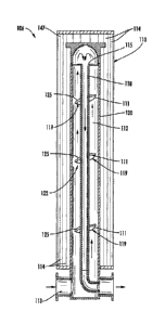
[0029] Referring to FIG. 1, the reference numeral 10 refers in general to a
radiation treatment
device. The device 10 comprises a treatment chamber 12 and a radiation source
14 disposed in
close proximity thereto, shown in FIG. 4, The treatment chamber 12 comprises a
header 16,
inner and outer tubes 18 and 20, a static mixer 22, and an end cap 24. The
header 16 has an outer
housing 26, an inner header tube 28, an input pipe 30 with an input opening
32, and an output
pipe 34 with an output opening 36. The outer housing 26 is open at the top,
closed at the bottom,
and has two side openings disposed on opposite sides, with one side opening
being larger than
the other. A mount 38 is secured to the bottom wall of the outer housing 26,
The input pipe is
CA 03021376 2018-10-17
WO 2017/188915
PCT/US2016/029114
affixed to the outer housing 26, aligned with the larger of the two side
openings The output pipe
34 is affixed to the outer housing 26 aligned ith the smaller of the two other
side openings. The
input and output pipes 30 and 34 both have inner diameters of approximately
1.5 inches. The
inner diameter of the output pipe 34 is larger than the diameter of the side
opening. The inner
header tube 28 has an input opening centrally disposed and coaxially aligned
with the outer
housing 26 and an output opening aligned with the smaller of the two side
openings. The inner
diameter of the inner header tube 28 is substantially the same as the diameter
of this side
opening. The header 16 is preferably made of stainless steel and is of clean
in place construction.
It is of course understood that the header 16 may be made of any number of
different materials or
combinations of materials. It is also understood that the header 16 may be
assembled or
fabricated from a number of different parts or may be cast or molded as one or
more integral
pieces.
[00301 The outer tube 20 is made of a material that is transparent to UV
radiation or to the type
of radiation used. The outer tube 20 is preferably constructed of a polymer,
is more preferably
constructed of a fluoropolymer, and is most preferably constructed of
fluorinated ethylene
propylene. The outer tube may of course be constructed of any number of
materials known to
possess the desired degree of transparency. The outer tube 20 has a length of
approximately 60
inches and has an inner diameter of approximately 1.25 inches. A lower portion
of the outer tube
20 is secured to the header 16, such as by using a hose clamp 40. The end cap
24 is affixed to an
upper portion of the outer tube 20, such as by using a hose clamp 40. A lower
surface 42 of the
end cap 24 is curved to assist in redirection of the liquid with minimal
pressure drop. The cap 24
is preferably stainless steel,
CA 03021376 2018-10-17
WO 2017/188915
PCT/US2016/029114
[00311 An output end of the inner tube 18 is affixed to the input end of the
inner header tube 28,
and the inner tube 18 extends coaxially aligned within the outer tube 20 along
most if not all of
the height, or longitudinal length, of the outer tube 20. The inner tube 18 is
preferably stainless
=
steel having an inner diameter of substantially within a range of from
approximately 0,5 inch to
approximately 3.25 inch The inner tube has an outer diameter that is
substantially within a range
of approximately from approximately 0.75 inch to approximately 3.5 inch The
outer diameter of
the inner, tube 18 and the inner diameter of the outer tube 20 are preferably
selected to provide a
relatively narrow annulus 44 between the two having a width of approximately
0.25 inch. An
inner surface of the inner tube 18 defines an inner flow path.
[00321 An inner surface of outer tube 20 and an outer surface of inner tube 18
define an outer
flow path. An opening in a distal end of the inner tube 18 places the outer
flow path in fluid flow
communication with the inner flow path. The outer surface of the inner tube 18
is not transparent
with respect to the radiation from the radiation source 14 and is preferably
reflective of the
radiation.
[00331 The static mixer or helical member 22 is an auger style static mixer
that is affixed to the
outer diameter of the inner tube 18, such as by welding. The mixer 22 extends
between the outer
wall of the inner tube 18 and the inner wall of the outer tube 20 and
preferably contacts the inner
wall of the outer tube 20. The mixer 22 is preferably stainless steel.
[00341 Different degrees of winding may be used depending upon desired
characteristics of the
device 10. In one embodiment the winding provides a liquid travel path of
approximately 3.9
inches for each 1 inch of annulus 44 height For a treatment chamber 12 in
which the height of
12
CA 03021376 2018-10-17
WO 2017/188915
PCTIUS2016/029114
the annulus 44 area is approximately 60 inches, this would provide a liquid
travel path of
approximately 234 inches.
10035] Referring to FIG. 2, a modular illumination unit 46 is provided, formed
from two mirror
image sections 47. The sections 47 are connected to one another by a hinge 49
or in any
conventional manner, Each section 47 comprises a plurality of bulbs 14, one or
more reflectors
48, and a bracket 50. The bracket 50 supports and aligns the bulbs 14 and
supports and aligns the
reflector or reflectors 48 positioned adjacent to the bulbs 14. The reflector
48 is configured with
a curved portion or segment, such as a semi -circular, hyperbolic, or
parabolic shaped portion or
segment, associated with each bulb 14, disposed and aligned to reflect and
focus radiation
emitted from outer portions of the bulb 14 back toward the treatment chamber
12. The segments
are disposed so that the reflector 48 is generally clamshell shaped. In that
regard, a cross section
of one segment falling in a common plane of a cross section of an adjoining
segment does not
form a portion of a common circle or semi- circle with the cross section of
the adjoining
segment, Each cross section is preferably semi- circular, and each cross
section of a segment has
an are length that is greater than approximately 450. The inner 8-urface of
the reflector= 48 is
selected to be highly reflective of the radiation used. For example, if a UV
bulb 14 is used, the
inner surface is preferably polished aluminum. Each section 47 is secured to
its mating section
47 and is secured within the cabinet 66 in any number of ways, such as being
secured to a back
wall of the cabinet or to brackets disposed within the cabinet 66. In the
embodiment shown, one
section 47 is disposed toward a back portion of the cabinet 66, and a mating
section 47 is
.disposed toward a front portion of the cabinet 66 so that the front section
47 may be easily
opened to provide access to the treatment chamber 12 and to the sections 47 of
the illumination
unit 46. Each section 47 is independently removable without the need to remove
an associated
13
CA 03021376 2018-10-17
WO 2017/188915
PCT/US2016/029114
treatment chamber or mated section 47. The brackets 50 of each section 47 are
disposed to place
the bulbs 14 in very close proximity to the outer surface of the outer tube
20. In the embodiment
shown, in which the modular concept is used, a separate modular illumination
unit 46 is
associated with each treatment chamber 12. An extra or spare modular
illumination unit 46 may
be provided along with the device 10. This will reduce down time by making it
easy to quickly
replace an installed unit 46 with a spare unit 46 if the installed unit is in
need of repair,
maintenance, or replacement.
[00361 In an alternate embodiment depicted in FIGS. 3 & 4, one or more bulb
racks 52 may be
used to support and align a plurality of outer tubes 20 of a plurality of
treatment chambers 12,
along with the bulbs 14 and reflectors 48 to be used with each treatment
device 10. As seen in
FIG. 3, sets of holes or openings 54 and 56 arc provided to support and align
the outer tubes 20
and bulbs 14, respectively.
100371 Referring to FIG. 5, input and output manifolds 58 and 60 are provided
and are disposed
to allow for parallel flow of a liquid through a plurality of adjacent
treatment chambers 12. The
manifolds are provided in a modular arrangement with a first set of associated
input and output
manifold segments 58a and 60a, a second set of associated input and output
manifold segments
581) and 60b, and so on for the desired number of treatment chambers 12 to be
used, The length
62 of the each input and output manifold 58,60 segment is equal to the
distance 64 between the
input opening 32 of the input pipe 30 and the output opening 36 of the output
pipe 34, This
allows each treatment chamber 12 to be quickly and easily adjusted to provide
for either parallel
flow as seen in FIG. 5 or to provide for series flow as seen in FIG. 6.
14
CA 03021376 2018-10-17
WO 2017/188915
PCT/US2016/029114
(00381 FIG, 6 shows a plurality of treatment chambers 12 arranged to provide
for series flow
through a plurality of treatment chambers 12. In this arrangement, the output
opening 36 of an
output pipe 34 of a first treatment chamber 12 is aligned with an input
opening 32 of an input
pipe 30 of a second treatment chamber 12, and so on for the desired number of
treatment
chambers 12.
100391 As shown in FIG. 7, a 1JV disinfectant system 6 may include a radiation
treatment device
positioned in a cabinet 66 and including related components. One or more
treatment
chambers 12 and sets of associated bulbs 14, reflectors 48, and input and
output manifolds 58,60
are housed within the cabinet 66. The cabinet 66 is preferably made primarily
of stainless steel,
Other components may be disposed within or positioned near the cabinet 66. For
example, a
power line 68 may supply power to controls 70 and to ballast 72 associated
with each bulb 14,
which may be housed in the cabinet 66 or separately above the cabinet 66. A
fan 74 may be
provided for cooling the ballast 72 and controls 70, and drain pipes 78 may be
provided in the
cabinet 66 floor. In the embodiment shown, a separate fan 74 may be associated
each modular
illumination unit 46, with the fan 74 disposed to provide a positive pressure
cabinet.
[00401 It is of course understood that any number of different fan 74
arrangements may be used
and that one or more fans may be disposed to provide either a positive
pressure cabinet or a
negative pressure cabinet. One or more input Or output pipes 80,82, and 84 may
be provided,
disposed in lower side walls of the cabinet 66. As best seen in FIG. 8, outer
pipes 80 and 82 are
disposed to align with input and output manifolds 58 and 60, respectively, to
provide a path for
parallel flow of liquid through the treatment chambers 12 such as when the
treatment chambers
12 are aligned as depicted in FIG. 5. The centrally located pipes 84 are
disposed to align with
CA 03021376 2018-10-17
WO 2017/188915
PCT/US2016/029114
input and output pipes 30 and 34 of the treatment chambers 12 when the
treatment chambers 12
are aligned for series flow, such as seen in FIG. 6.
[0041] Referring to FIGS. 5 & 6, in operation, a plurality of treatment
chambers 12 are aligned
as desired to provide for parallel or series flow through the desired number
of treatment
chambers 12. It is of course understood that a single treatment chamber 12 may
also be used if
desired. Once the treatment chanibers 12 are aligned as desired and the
cabinet doors 86 closed
for added protection against exposure to UV radiation, the bulbs 14 are
activated to provide UV
radiation. The liquid to be treated is then provided to the device 10 at the
desired pressure and
flow rate. It is understood that the device 10 may be used in connection with
most any liquid,
including but not limited to clear, or opaque liquids such as water, including
wastewater, juices,
brines, marinades, beverages, and the like.
100421 In parallel flow (FIG, 5) the liquid will pass through and fill the
desired number of input
manifold segments 58a, 58b, 58e and will pass from each input manifold 58
segment into an
associated treatment chamber 12. As best seen in FIG..!, the liquid passes
through the input pipe
30, through the housing 26, and into the annulus 44 between the inner tube 18
and outer tube 20.
The static mixer 22 routes the liquid in a tight spiral pattern along a
helical path upward through
the annulus 44 to an upper portion of the treatment chamber 12. As the liquid
passes through the
narrow annulus 44 in close proximity to the bulbs 14, UV radiation from the
bulbs 14 provides
the desired degree of disinfection. The use of the auger style static mixer 22
provides for
significant mixing and churning of the liquid as it passes upward through the
annulus 44 so that
different portions Of the liquid are constantly being moved closer to and
further from the bulbs
14, This ensures thorough and even radiation exposure throughout the liquid
and greatly reduces
the chances of leaving isolated portions relatively untreated or significantly
over treated The end
16
CA 03021376 2018-10-17
WO 2017/188915 PCMS2016/029114
cap 24 arrests upward flow of the liquid and redirects the liquid to flow
downward through the
inner tube 18. The liquid then passes through the inner tube 18, through the
inner header tube 28,
and through the output pipe 34.
100431 If the treatment chamber 12 is aligned to provide for parallel flow
(FIG. 5), the liquid
passes from the output pipe 34 to and through the associated output manifold
60 segment for
further use or treatment If the treatment chamber 12 is aligned to provide for
series flow (FIG.
6), the liquid passes from the output pipe 34 of one treatment chamber. 12 to
the input pipe 30 of
another treatment chamber 12 to repeat the process described above.
100441 The rugged device 10 may be operated under wide ranges or pressures and
flow, rates
without fear of damaging the device 10. For example, the device 10 may be
safely operated at a
working pressure reaching or exceeding a pressure that is preferably
substantially within a range
of from approximately 30 psig to approximately 60 psig and that is more
preferably
approximately 57 psig. The device 10 may withstand burst pressures reaching or
exceeding a
pressure that is preferably substantially within a range of from approximately
100 psig to
approximately 300 psig and that is more preferably approximately 286 psig.
Desired flow rates
for many applications will typically be within a range of from approximately 1
gallon per minute
to approximately 20 gallons per minute. Similarly, desired flow rates for
typical clean in place
cleaning will typically be less than or equal to approximately 25 gallons per
minute. Still, much
higher flow rates may be desirable for some applications, such as for the
batch processing of
juice. In the batch processing ofjuice, it is sometimes desirable to process
flow rates reaching or
exceeding approximately 70 gallons per minute. The system 6 may be configured
to safely
process flows rates of up to approximately 30 gallons per minute, up to
approximately 55 gallons
17
CA 03021376 2018-10-17
WO 2017/188915
PCIMS2016/029114
per minute, or approximately 80 gallons per minute. A treatment chamber 12
typically processes
approximately 10 to 12 gallons per minute. Parallel flow is typically used for
higher rates
100451 Other modifications changes and substitutions are intended in the
foregoing, and in some
instances, some features will be employed without a corresponding use of other
features. For
example, any number of treatment chambers 12 may be used, from one to several,
Similarly, a
configuration of eight bulbs 14 per treatment chamber 12 may be used, but any
number of bulbs
14 may be lased in connection with a treatment chamber 12, from one to
several, Also, any
number of different types of mixers 22 may be used in the annulus 44, or a
mixer 22 may be
omitted. Further, any number of different flow paths may be used, including
but not limited to a
flow, path that is roughly the reverse of that described above. Similarly,
strictly series flow may
be used, strictly parallel flow may be used, or any number of combinations of
series and parallel
flows may be used. Also, the header 16 may be disposed in different locations,
such as at the top
of the treatment chamber 12. Similarly, any number of different methods may be
used to route
the liquid to or from the annulus 44 area and to or from the inner tube IS
Although bulbs 14
providing UV radiation are preferred, any number of different types of
radiation and types of
radiation sources 14 may be used depending upon the desired application.
Further, the reflectors
48 may take any number of shapes, sizes or configurations or may be omitted.
100461 FIGS. 9A St 9B and FIGS. 10A & 10B illustrate additional embodiments of
a static
mixer 122 of a treatment device 110 for use with a UV disinfectant system 106
(see, e.g., FIGS.
11-13). Elevated views are shown in FIGS. 9A & 10A. Axial views are shown in
FIGS. 9B &
10B. The static mixer 122 may include dimensions similar to those described
above as modified
below with respect to the static mixer 22. The static mixer 122 may be
positioned within a
18
CA 03021376 2018-10-17
WO 2017/188915
PC111752016/029114
treatment chamber 112 adjacent to a flow path of liquid through the chamber
112, an example of
which is illustrated in FIG. 11 (arrows).
100471 The static mixer 122 may be structured to create turbulence in liquid
flow thereby
mixing, e.g., turning over, churning, circulating, or otherwise agitating the
liquid to thereby
impede laminar flow. The static mixer 122 comprises extensions, referred to
herein as vanes
111, located along the outer surface of the inner tube 118. The vanes 111 are
positioned along
the flow path and are dimensioned to create turbulence by impeding a direct
flow of liquid
through the treatment chamber 112. In particular, the vanes 111 are
dimensioned to create
turbulence along the flow path to prevent laminar flow. Thus, when liquid
flows along the flow
path between the inner tube 118 and outer tube 120, the liquid may be exposed
to UV light that
shines through a transparent portion of the outer tube 120 and into the flow
path between the
inner tube 118 and the outer tube 120 to act on the flowing liquid, For
example, the vanes Ill
may be dimensioned to create eddies of circulating liquid to disrupt laminar
flow and to increase
the proportion of the liquid that passes near the inner surface of the outer
tube 120, The intensity
of the UV light drops as the UV light passes through more liquid. So the
intensity is greatest,
and the disinfecting effect is greatest, closest to the inner surface of the
outer tube 120. The rate
at= which the UV light intensity drops as it passes through the liquid may
vary depending on
factors such as light intensity, liquid composition or transparency/turbidity,
outer tube
composition or transparency, flow rate, etc.
100481 The vanes ill shown in FIGS. 9A & 9B and FIGS. 10A & 10B comprise a
plurality of
vanes 111 positioned along the height or longitudinal length, of the inner
tube 118 and extend
axially into the flow path between the inner tube 118 and outer tube 120 to
thereby agitate the
liquid as it flows there along under the bulbs 114. The vanes 111 are
preferably formed from
19
CA 03021376 2018-10-17
WO 2017/188915
PCT/US2016/029114
materials resistant to corrosion, such as stainless steel, plastics, etc. The
inner tube 118 may be
formed of materials resistant to corrosion, such as stainless steel, plastics,
etc., which may be the
same or a different material than the vanes 111.
100491 The vanes 111 extend axially from the inner tube 118 into the flow path
between an inner
axial end 121 and an outer axial end 123. The vanes 111 extend axially, into
the flow path
toward the outer tube 120 but do not extend to the inner surface of the outer
tube 120, Rather, a
gap 119 is provided between the outer axial end 123 and the inner surface of
the outer tube 120
to create greater turbulence. In other embodiments, the vanes 111 may extend
axially to the
inner surface of the outer tube 120. The vanes 111 further extend a
circumferential distance
around the inner tube 118 between a first circumferential end 125 and a second
circumferential
end 127. A first face 129 and a second face 131 are positioned between the
inner axial end 121
and the outer axial end 123 and the first circumferential end 125 and the
second circumferential
end 127. The vanes Ill may be tilted, e.g., sideways, or spiraled and extend
about half-way
around the circumference of the inner tube 118, In other embodhnents, the
inner tube 118 may
not be a tube, but may be a surface within the chamber 112 that is not a part
of a separate tube
with respect to another wall, e.g., the outer tube 120. Tor example, the flow
path may be defined
along a single tube or continuous arrangement of walls about the perimeter of
the flow path. The
vanes 111 may extend into the flow path from a first portion of the wall
toward a second portion
of the wall such that a gap is formed between the vanes 111 and the second
portion of the wall.
In one embodiment, the second portion of the wall is transparent to UV light.
100501 The vanes 111 in the embodiments illustrated in FIGS. 9A & 9B and FIGS.
10A & 10B
extend circumferentially around the inner tube 118 about 180 . In other
emboditnents, the static
mixer may include one or more vanes 111 that extend less than 1800 around the
inner tube 118,
CA 03021376 2018-10-17
WO 2017/188915
PCT/US2016/029114
such as between 180 and 135 , between 180 and 90 , between 180 and 45 ,
between 135 and
90 , between 135 arid 45 , between 90 and 45 , or about 170 , abont 160 ,
about 150 , about
140 , about 130, about 120 , about 120 , about 110 , about 100 , about 90 ,
about 80 , about 70 ,
about 60 , about 50 , about 40 , about 30 , about 20 , or about 10 . In, some
embodiments, the
static mixer may include one or more vanes 111 that extend greater than 180
around the inner
tube 118, such as between 360 and 315, between 360 and 270 , between 360
and 225 ,
between 360 and 1806, between 315 and 270', between 315 and 225 , or about
360', about
370 , about 350 , about 340 , about 330 , about 320, about 310 , about 300%
about 290 , about
280 , about 270% about 260 , about 250 , about 240 , about 230', about 220%
about 210 , about
200 , or about 190 .
100511 The vanes 111 may be aligned such that each is positioned along a
corresponding
circumferential portion of the inner tube 118, as shown in the embodiments
illustrated in FIGS.
9A & 9B and FIGS. 10A & 100. In other embodiments. The vanes 111 may be offset
such that
the vanes 111 occupy different eiretunferential portions of the inner tube
118, which may overlap
along one or more portions of vanes 1 1 1 along the longitudinal length of the
inner tube 118. The
vanes 111 may be progressively offset such that a first vane 111 is positioned
along a first
circumferential length of the inner tube 118, a second vane 111 is positioned
along a second
circumferential length of the inner tube 118, adjacent to the first with
respect to the
circumference of the inner tube 118, and a third vane 111 is positioned along
a third
circumferential length of the inner tube 118, adjacent to the second with
respect to the
circumference of the inner tube 118. The vanes 111 may similarly be offset in
a staggered
formation with respect to the circumference and longitudinal length of the
inner tube 118.
21
CA 03021376 2018-10-17
WO 2017/188915
PCT/US2016/029114
100521 The embodiments illustrated in FIGS. 9A & 98 and FIGS. 10A & 108
comprise mixers
122 including three vanes 111. However, in other embodiments, any number of
vanes 111 may
be used. For example, fewer or additional vanes 111 may be includes such as
two vanes 111,
four vanes Ill, five vanes 111, six vanes 111, or more. The vanes 1 l 1 may be
spaced apart with
respect to the longitudinal length of the inner tube 118. For example, the
vanes 111 may be
spaced apart between one that and ten foot, one foot and six foot, one foot
and three foot, two
foot and six foot, two foot and three foot, or other distance. The spacing may
be equivalent, as
shown, or the vanes 111 may be bunched or concentrated along a longitudinal
length of the inner
tube 118 relative to one or more other longitudinal lengths of the inner tube
118, The vanes 111
illustrated also include similar dimensions; however, in some embodiments, the
dimensions of a
first vane 111 may be less than the dimensions of a second vane 111 or a
second vane Ill and
third vane 111.
[0053] The vanes Ill transverse a portion of the flow path adjacent to the
inner tube 118 thereby
impeding laminar flow or otherwise creating turbulence. The first face 129 is
positioned at a
non-perpendicular angle with respect to the direction of flow. In other
embodiments, the first
face 129 may be positioned perpendicular to the direction of flow. In the
embodiment illustrated
in FIGS. 9A & 9B, the first thee 129 presents a substantially straight angle
surface. In some
embodiments, the first face 129 may present a concave or convex surface to
impede laminar
flow, as illustrated in FIGS. 10A & 1.08.. As shown in the embodiment
illustrated in FIGS. 9A
& 98 the first face 129 forms an angle with the outer surface of the inner
tube 118 that is about
90 or greater. In the embodiment illustrated in FIGS. 10A & 108, the first
face 129 forms an
angle with the outer surface of the inner tube 118 that is less than 90 along
all or a portion of the
circumferential length of the vane. In other embodiments, the first face 129
may form an angle
22
CA 03021376 2018-10-17
WO 2017/188915
PCT/US2016/029114
with the outer surface of the inner, tube 118 that is less than 90 along a
first portion of the
cireumferential length of the vane 111 and greater than 90" along a second
portion of the
circumferential length of the vane IlL. The first face 129 of the vanes 111
shown in FIGS, 10A
& 10B include a substantially smooth surface extending from the inner axial
end 121 to the outer
axial end 123. In other embodiments, the first face 129 or the second face 131
may include
additional turbulence features, such as bumps, divots, slots, pits, one or
more grooves or groove
patterns, or other turbulence producing feature. In the embodiment illustrated
in FIGS. 9A &
9B, the surface of the first faces 129 include turbulence features comprising
a plurality of raised
bumps 133, The bumps 133 may be positioned adjacent to or along the interface
between the
first face 129 and the outer surface of the inner tube 118. The bumps 133 may
be formed by any
suitable method. For example, the bumps 133 may be formed by tack welds. In
the illustrated
embodiments, the second face 131 is positioned at a non-perpendicular angle
with respect to the
direction of flow. In other embodiments, the second face 131 may be positioned
at a
perpendicular angle with respect to the direction of flow. The second face 131
may include a
substantially flat angle surface, as shown in FIGS. 9A & 9B, or include a
concave or convex
surface, as shown in [ICS WA & 10B. The second face 131 shown in FIGS. 9A &
913 form an
angle with the outer surface of the inner tube 118 that is about 90' or less.
In other
embodiments, the second face 131 may form an angle with the outer surface of
the inner tube
118 that is greater than 90' along all or a portion of the circumferential
length. of the vane, such
in the embodiment illustrated in FIGS. 10A & 10B. In another embodiment, the
second face
131 may form an angle with the outer surface of the inner tube 118 that is
greater than 90' along
a first portion of the circumferential length of the vane 111 and less than
90' along a second
portion of the circumferential length of the vane 111. The surface of the
second face 131 may
23
CA 03021376 2018-10-17
WO 2017/188915
PCT/US2016/029114
further include turbulence features such as bumps, divots, slots, pits, one or
more grooves or
groove patterns, or other turbulence producing feature. The bumps may be
positioned adjacent
to or along the interface between, the second face and the outer surface of
the inner tube 118.
The bumps may be formed by tack welds, for example.
f00541 The thickness of the 'vanes 111 in the embodiments illustrated in FIGS.
9A & 9B and
FIGS. 10A. & 10B are about the same from the inner axial end 121 to the outer
axial end 123. In
other embodiments, the thickness may increase from the inner axial. end 121 to
the outer axial
end 123. In one embodiment, the thickness decreases from the inner axial end
121 to the outer
axial end 123.
.[0055] The thickness of the vanes 111 in the embodiments illustrated in FIGS.
9A & 9B and
FIGS. 10A & 1013 are about the same from the first circumferential end 125 to
the second
circumferential end 127. In other embodiments, the thickness may increase or
decrease from the
first circumferential end 125 to the second circtimferential end 127.
[0056] The first circumferential end 125 and the second circumferential end
127 of the vanes
111 shown in the illustrated embodiment of FIGS. 10A & 10B taper toward the
inner tube 118.
In other embodiments, one or both of the first circumferential end and second
circumferential
end do not taper. For example, the vanes 111 shown in the embodiment
illustrated in FIGS. 9A
& 9B include defined circumferential ends 125, 127 that extend to the inner
tube 128: In one
embodiment, a portion of the outer axial end 123 extends axially outward a
greater distance than
another portion of the outer axial end 123. For, example, a portion of the
outer axial end 123
adjacent the first circumferential end 125 may extend a greater distance
axially than a portion of
the outer axial end 123 adjacent the second circumferential end 127 or along a
central portion of
24
CA 03021376 2018-10-17
WO 2017/188915
PCT/C52016/029114
the vane 111. The first circumferential end 125 adjacent to the outer axial
end 123 may extend a
same, greater, or lesser circumferential length than the first circumferential
end 125 adjacent to
the inner axial end 121. The first circumferential end 125 or the second
circumferential end 127
may extend axially outward from the inner tube 118 a greater distance than a
central portion of
the vane 111 along the outer axial end 123.
100571 FIG. II illustrates a UV disinfectant system 106 comprising a treatment
device 110,
shown in a sectional view, 1,vherein the static mixer 122 is positioned in a
chamber 112 and
surrounded by a radiation section 147 comprising a plurality of radiation
emitting bulbs 114,
shown as comprising UV bulbs. An additional radiation section may be
positioned over the
illustrated radiation section 147 to encapsulate or surround the chamber 112
with UV radiation.
The radiation sections 143 may be hinged such that two may be separated by
pivoting of the
hinge along one side to access the chamber 112 or bulbs 114. The arrows
indicate direction of
liquid flow through the chamber 112. Liquid to be treated is pumped into the
chamber through
inflow port 113. The liquid is then flowed along the treatment flow path
defined between the
walls of the chamber 112. The vanes 111 of the static mixer 122 impede laminar
flow along the
flow path. A gap 119 may be formed between the vane 111 and the adjacent wall
of the chamber
112 within the flow path. The gap 119 may be defined between the vane 111 and
the transparent
portion of the chamber wall. As shown, the gap 119 is defined between the
outer axial end 123
of the vane 111 and the chamber wall formed by the inner surface of the outer
tube 120. The
static mixer 122 is shown positioned in a treatment chamber 112 having walls
comprising co-
axially aligned inner 118 and outer tubes 120; however, other arrangements may
be used
according to various embodiments. For example, the static mixer 122 may
comprise vanes 111
CA 03021376 2018-10-17
WO 2017/188915
PCT/1JS2016/029114
extending from :the outer tube 120 toward the inner tube 118. Gaps 119 may
similarly be formed
therebetween.
100581 FIG. 12A illustrates a IN disinfectant system 106 comprising a cabinet
166 according to
various embodiments. FIG. 128 illustrates a view or the system 106 with the
doors 186
removed. The cabinet 166 houses one or more treatment devices 10, 110 of the
treatment system
1.06.
100591 The system 106 may include sensors (not shown) configured to sense
operational
conditions Sensor wiring 150 is shown in FIG. 1213; however, in some
embodiments, one or
more sensors may transmit or receive operation data wirelessly. Referring th
FIG, 13 providing
a schematic illustration of one embodiment of the system 106, the sensors may
include one or
more air temperature sensors 151 to measure an temperature within the cabinet
166. The sensors
may also include one or more liquid temperature Wnso3 153 to measure liquid
temperature
within the chamber 112. The sensors may also include one or more flow meters
155 to measure
flow rate of liquid pumped through the chamber 112 by one or more pumps 161.
100601 Referring to FIGS. 12A-13, the system 196 may include blowers 143 are
positioned to
provide circulation or ventilation of the cabinet thereby dissipating heat
build-up to prevent
excessive air temperatures from damaging components of the system 106. Blowers
143 may
include one or more fans, pumps, or other devices/structures configured to
actively encourage an
to flow from one location to another location. Blowers 143 may be positioned
at the upper end
135 and lower end 137 of the cabinet 166. Ports 141 may extend through the
cabinet 166
through which the blowers 143 urge air flow. Wiring 150 may operably couple
the blowers 143
26
CA 03021376 2018-10-17
WO 2017/188915
PCT/US2016/029114
and sensors 151, 153, 155 with the controller 175. The wiring 150 may include
a connection 167
to connect to the control panel 171.
100611 The ports 141 and blowers 143 may be positioned with respect to the
cabinet 166 to
prevent cross circulation issues. In the illustrated embodiment, the system
106 includes two
blowers 143 positioned at opposite corners of the cabinet 166, cattycorner
across the box at
opposite ends.. In other embodiments, the ports 141 may be located at other
sides of the upper
and lower ends 135, 137 of the cabinet, such as along a back wall, the doors
186, or either the top
or bottom wall The blowers 143 may be positioned to blow air out of the
cabinet 166. The
blowers 143 may be located within the cabinet 166, as shown, or external to
the cabinet 166.
Additional ports 141 and blowers 143 may also be used along the upper end 135
and lower end
137 or, in one embodiment, along a middle portion of the cabinet, A vent 139
may extend into
the cabinet. 166 to provide ventilation. The vent 139 may be positioned along
a wall of the
cabinet 166. The vent 139 may be located along an upper end 135 of the cabinet
166, e.g., along
a side wall or top of the cabinet 166, along a central portion of the cabinet
166 between the upper
end 135 and lower end 133, or along the lower end 135 of the cabinet, e.g.,
along a lower side
wall or bottom of the cabinet 166. The vent 139 may include louvers to allow
the pressure
within the interior of the cabinet 166 to equalize. Thus, air may move into
the interior of the
cabinet 166 through the vent 139 as air is moved out of the interior of the
cabinet 166 by the
action of the blowers 143. In one embodiment, an additional blower may be used
with the vent
139. Multiple vents 139 may also be used. Blower ports 145 arc formed through
the cabinet 166
through which the blowers 143 may direct air. The blowers 143 may be
positioned to move air
out of the interior of the cabinet 166 from the tower end 137 and upper end
135, as shown, and
the vent 139 may be located along a middle portion of the cabinet 166 to
provide circulation of
27
CA 03021376 2018-10-17
WO 2017/188915
PCT/US2016/029114
air through the interior of the cabinet 166 while avoiding cross circulation
across the chamber
walls.
[00621 The blowers 143 may comprise adjustable speed blowers 143. For example,
the speed of
the blower 143 may be adjusted to increase or decrease a speed of the blower
143. The speed
may be adjusted by a switch. The switch may be operable by manual
manipulation, e.g., by a
user, at a location of the blower 143, which may be associated with the blower
143 or switchable
at a user interface 169 of a control panel 171 or, in one embodiment, the
switch may be operable
remotely via an operation of a controller 175 comprising a user intei face 169
accessible to
monitor or control operations of the system 106 (see FIG. 13). The blower 143
may further
comprise a variable frequency drive (NM") blower. 143.
[00631 With further reference to F1G. 13, the system may further include a
controller 175 to
monitor or control operations of the system 106. The controller 175 may
include one or more
processors, servers, as well as databases, networks or network devices, and
peripherals
configured to obtain and transmit data and initiate control operations
configured to perform in
whole or in part the operations of the system 106. As shown, the controller
175 comprises a
control module 107, e.g., one or more electronic data processors or central
processing units
having logic control funetionalitics. The controller 175 further comprises a
memory unit
comprising one or more computer readable data storage mediums, e.g.,
electronic data storage
mediums such as recording media, read-only, volatile, non-volatile, semi-
conductor based, or
other data storage mediums known in the art. The computer readable storage
medium, for
example, includes one or more data storage mediums having stored thereon one
or more
programs or applications comprising software, firmware, or other instructions
stored in one or
more files executable by the processor of the control module to perform the
various operations
28
CA 03021376 2018-10-17
WO 2017/188915
PCT/US2016/029114
and functions of the controller 175. The instructions may include a monitoring
program or
operating system configured to monitor or control operations of the system 106
and interface
users or access devices 191, which may include interaction with additional
applications or
service, with the system 106.
100641 The controller 175 may be operationally associated with control and
monitoring
operational devices 199 such as actuators, valves, pumps, power switches, etc
for controlling or
monitoring operational conditions of the UV disinfectant system 106. For
example, the
controller 175 may be operationally associated with pumps 161, blowers 143,
and bulbs 114,
The controller 175 may be configured to initiate or otherwise provide control
instructions to the
LIV disinfectant system 106 to modulate operations in response to a
determination, e.g., to
maintain or address non-conforming set points.
100651 As introduced above, the controller 175 includes a controller 175
configured to execute a
monitoring program 120. The monitoring program 120 may include a web
application, service,
or bundled services in which various interfaces 169 such as local interfaces
187 or remote
interfaces 185 may interface with the controller 175 and monitoring program.
In various
embodiments, a local interface 187 may include the control panel 171. Remote
interfaces 185
may include access devices 191 programed to remotely interface with th
ontroller 175. In at
least one embodiment, access devices 191 include a notification device
configured to receive
notifications from the controller 175, Remote interfaces 185 may interface
with the controller
175 in a cloud platform environment. For example, the various services or
applications may be
executed in a cloud environment through interaction of the access devices 191
and controller
175.
29
CA 03021376 2018-10-17
WO 2017/188915
PCT/1JS2016/029114
100661 The controller j751 includes a control module comprising a digital
processor to route or
make available the operation data collected to one or more computer readable
storage mediums
or interfaces. The storage medium, for example, may be accessed by the control
module to=
retrieve, store, or archive operation data, which may include raw, processed,
or analyzed
operation data, events, as well as parameter definitions, including rules,
statistics, tables,
algorithms, or other data used to process or analyze data including generating
or identifying
operational conditions, as described in more detail below. For example, the
storage medium may
include files executable by the controller 175 to perform one or more aspects
of the monitoring
program_ The controller 175 may be under the control of the monitoring program
configured to
interface the functionalities of the controller with users and access devices
191. The monitoring
program may include set points, operational condition identifications, and
analysis parameters,
any of which may include customizable definitions to fit the desired
application For example,
the controller 175 may be operatively associated with one or more processes of
the UV
disinfectant system 106 to monitor, collect, analyze, process, and/or
communicate data indicative
of operational conditions, events, or states as defined by the monitoring
program. Example set
points that may be defined in the system 106 may include a liquid temperature
at the one or more
locations within the chamber 112, a flow rate at the one or more locations
within the chamber, or
an illumination of the bulbs 114. When a set point is found to be non-
conforming, e.g., at a
threshold level indicating a control operation the controller 175 may modify
an operation of the
UV disinfectant system in response to the non-conforming set point condition
For example, the
controller 175 may terminate power to the bulbs when the flow meter 155
measures no flow, the
air temperature sensor 151 measures an air temperature higher than an air
temperature set point,
the liquid temperature sensor 153 measures a liquid temperature higher than a
liquid temperature
CA 03021376 2018-10-17
WO 2017/188915
PCT/US2016/029114
set point, or the air temperature sensor measures an air temperature lower
than an air temperature
set point. The controller 175 may also terminate power to pump 161 or reduce
pump speed when
the liquid temperature sensor 153 measures a liquid temperature below a,
liquid temperature set
point, or supply power to the pump 161 or increasing speed of the pump 161
when the liquid
temperature sensor 153 measures a liquid temperature above a liquid
temperature set point. The
controller 175 may also be programed to supply power to the blowers 143 or
increase speed of
the blowers 143 when the air temperature sensor 151 measures an air
temperature above an air
temperature set point.
[00671 The system 106 may comprise one or more networks including networked
devices, e.g.,
nodes or endpoints, configured to communicate via wired or wireless
connections. Networks
may comprise local, virtual, wide area, cloud/internct area, or internet-based
aspects. The
networks may include one or more distributed communication networks that may
include virtual
hardware, distributed databases, parallel or distributed computing schemes,
service oriented
application architectures, public, private, or hybrid clouds, open
architectures or architectures
utilizing web API, web applications, or mashups, and may employ client-server
or peer-to-peer
models. The controller 175 may also include a communication port 183
configured to transmit
and receive data, which may be transmitted and received over a network, The
communication
port 183 may include one or more data ports, communication ports,
transmitters, receivers,
transceivers, network cards, modems, gateways, routers, switches, firewalls,
local, virtual, wide
area, cloud/internet area, or intemet-based distributed networks, Ethernet,
wireless or wired
digital communication devices, telecommunication devices, monitors, speakers,
lights, buttons,
knobs, or peripherals. The controller 175 may include a wired or wireless data
or
communication port 183 into which a user may couple a local or remote user
access device 191
31
CA 03021376 2018-10-17
WO 2017/188915
PCT/US2016/029114
such as a computer, tablet, notebook, smart phone, mobile communication
device, programing
card, flash drive, memory stick, or special purpose diagnostic, programming,
or system
administration device. For example, in one embodiment, the controller 175
includes a data port
181 configured to receive a data storage device such as a flash dove defining
one or more set
points, administrative parameters, or security definitions. In some
embodiments, the
communication port 183 of the control panel 171 provides an access point to
user access devices
191 to access the monitoring program and its. functionalities,
[0068] The controller 175 may include a user interface 169 comprising a
control panel 171. The
panel 171 may be a standalone unit for control of the device 110 and
associated operations. The
control panel 171 may receive operation data from the plurality of sensors
177, such as
measurement data from air temperature sensors 151, liquid temperature sensors
153, and flow
meter 155. The control panel 171 may include a graphical user interface 157
for displaying
information related to the operation of the UV disinfectant system 106. The
control panel 171
also comprises various peripherals such as selection devices and LED
indicators. In one
embodiment, the control panel 171 include a touch screen. The user interface
169 may be
programe,d to interface users with the operations of a monitoring program to
view, define, or
modify operation conditions or set points.
100691 The control panel 171 may be located locally with respect to the
cabinet 166 to provide
users with a local access point to the contioller 175. In various
configurations, users may use the
control panel 171 to update or modify set points or query the computer
readable storage medium
for operation data or analysis, e.g., to generate or define reports, view
event legs, historical or
projected performance, or real-time operation data or operational conditions
or to initiate
collection of real-time operation data. The control panel 171 may also allow
users to access,
32
CA 03021376 2018-10-17
WO 2017/188915
PCT/US2016/029114
define, or modify security features such as permissions or user access levels,
perform,
administrative tasks, override automated operations, or initiate, terminate,
or modify operations.
(00701 The graphical user interface 157 may include presentation of operation
data. The
graphical user interface 157 may also include a touch screen interface
providing local interface
187 with the control panel 171 A user may access the control panel 171
locally, or remotely in
some embodiments, to view the current state of multiple aspects of the UV
disinfectant system in
real-time. In one embodiment, the user may select one of the identified set
points to view or
change the values defining the current set points. Typically, it will be
preferable to require the
user to establish authorization, e.g., by providing an identification or
authorization code, before
allowing the user to modify certain or any set point definitions or values.
100711 The control panel 171 may be provided on the outside of the cabinet 166
or another
location associated with the cabinet 166. The graphical user interface 157 may
include LED
lights that indicate measurement data from the sensors. The control panel 171
may also be
configured to track operational life of the bulbs 114, which may allow for
efficient preventative
maintenance, reducing downtime.
100721 The user interface 169 may also include a remote user interface 185
accessible via a
network 193. The network 193 may include a local or distributed network, for
example. In one
embodiment, the network 193 allows users to remotely access the controller 175
via an internet
connection, which may include remote access to the outside control panel LED
data. Once
accessed by a remote access device 191, a user may remotely view operational
data, such as
measurement data, in real time. The= access device 191 may be configured with
an
monitoring/control application or the user may provide an authorization code
to access the
33
CA 03021376 2018-10-17
WO 2017/188915
PCTAIS2016/029114
operational data, e.g, current or historical operation data, control
operations, or update or define
checkpoints, For example, in some embodiments, users accessing the control
panel 171 remotely
via a remote access device 191 may access the control operations of the
control panel 171 to,
e.g., control power to bulbs 114, control power to or modulate speed of
blowers 143, control
power to or modulate speed of pumps 161. In one embodiment, a remote user
access device 191
may modify power delivery to the bulbs to turn on or turn off the bulbs,
changing a speed of
operation of the pump 161 to modify a flow rate or temperature of the liquid
pumped through the
chamber, or changing a speed of one or more blowers to modify air temperature
at one or more
locations within the cabinet.
[00731 The controller 175 is configured to operatively associate with one or
more sensors 177
positioned to sense, detect, or measure conditions of the UV disinfectant
system 106 in real-time.
The sensors 177 may include liquid temperature sensors 153, flow meters 155,
or air temperature
sensors 151, as described above with respect to FIG. 12A & 1213. The sensors
177 may be
positioned at one or more locations to detect and obtain operation data
associated operational
conditions. In various embodiments, the operation data associated with
operational conditions
may be communicated by the sensors 177, e.g., transmitted, mlayecl or muted
to, or otherwise
obtained by, to the controller 175 in real-time. Transmission of the operation
data may be by any
manner known in the art, e.g., via wired or wirt,sless communication. For
example, in one
embodiment, sensors 177 may be configured to transmit operation data via a
wired or wireless
transmitter or transceiver configured to transmit the sensed operation data to
the controller 175.
[00741 In one embodiment, the speed of the VFD blower 143 or adjustable speed
blower 143
may be dynamically controlled by the operation of the sensors, e.g., via set
points defined in the
system 106. For example, the controller 175 may be configured with set points
defining desired
34
CA 03021376 2018-10-17
WO 2017/188915
PCT/US2016/029114
operational criteria with respect to air temperature, liquid temperature,
liquid flow rates, power
delivery, projected component operational life spans, service intervals, etc,
When operational
data collected by the sensors 177 or calculated by the controller 175 are
determined to be non-
conforming, e.g, outside of defined set points such as meeting a threshold
difference in a set
point value, the control panel 171 may be configured to take an action defined
in the system 106.
For example, the strength of the UV and effectiveness of the disinfection may
be monitored by
the system 106. in one implementation, the flow meter 155 and liquid
temperature sensor 153
may be configured to provide data to the controller 175, which the controller
175 may compare
to a programed set point and thereafter terminate power to the bulbs 114 if
flow is below a flow
set point, e.g., reach ,.a threshold value, such as no flow, or the liquid
temperature is above a
liquid temperature set point Beneficially, turning off the bulbs 114 if there
is no flow or if the
temperature of the liquid gets too hot may prevent thermal damage to
components of the system
106 that could otherwise bring down the whole system 106.
[00751 In various embodiments, a liquid temperature sensor 153 may comprise a
thermocouple
to measure the liquid temperature and may comprise a switch that turns off the
pump 161 and
power delivery to the bulbs 114 when temperature rises above a desired
temperature. The
thermocouple may he utilized to measure the liquid temperature within the
chamber 112, which
may be at one or more locations, e.g., a or adjacent to the inflow port, along
the flow path, at or
adjacent to the outflow port, along the inner pathway of the inner tube 118,
or after the treated
liquid has exited the chamber The thermocouple may operate in conjunction with
the flow meter.
155. The thermocouple temperature sensor may also be utilized to control the
speed of the
blowers 143, which may be VFD blowers 143. In one embodiment, an air
temperature sensor.
151 may comprise a thermocouple measurement device including a switch to
modify operation
CA 03021376 2018-10-17
WO 2017/188915
PCT/US2016/029114
of the system 106, e.g., terminate power to the bulbs 114 when temperature
rises above a desired
temperature, temiinate power to blowers 143 or increase blower speed when
temperature rises
above a desired level, or terminate power to the pump 161 when temperature is
below a desired
temperature, such as when the bulbs 114 are not illuminated
OTHER MATTERS
[0076] The foregoing description of various embodiments is provided to enable
any person
skilled in the art to make and use the present invention and its embodiments.
Various
modifications to these embodiments are possible, and the generic principles
presented herein
may be applied to other embodiments as well.
[00771 It will be apparent to one of ordinary skill in the art that some of
the embodiments as
described hereinabove may be implemented in many different embodiments of
soRware,
firmware, and hardware in the entities illustrated in the figures. The actual
software code or
specialized control hardware used to implement some of the present embodiments
do not limit
the present invention.
[0078] As used herein, a "computer" or "computer system" may be, for example
and without
limitation, either alone or in combination, a personal computer (PC), server-
based computer,
main frame, server, microcomputer, minicomputer, laptop, personal data
assistant (PDA),
cellular phone, pager, processor, including wireless and/or wireline varieties
thereof, and/or any
other computerized device capable of configuration for receiving, storing
and/or processing data
for standalone application and/or over a networked medium or media. For,
example, various
embodiments may include access devices or be configured to communicate, e.g.,
transmit data or
interface, with the controller and program as described herein.
36
CA 03021376 2018-10-17
WO 2017/188915
PCT/US2016/029114
00791 Computers and computer systems described herein may include operatively
associated
computer-readable memory media such as memory for storing software
applications and
instructions used in obtaining, processing, storing and/or communicating data.
It can be
appreciated that such memory can be internal, external, remote or local with
respect to its
operatively associated computer or computer system. Memory may also include
any means for
storing software or other instructions including, for example and without
limitation, a hard
disk,
an optical disk, floppy disk, DVD, compact disc, memory stick, ROM (read only
memory),
RAM (random access memory), PROM (programmable ROM), EEPROM (extended erasable
PROM), and/or other like computer-readable media.
(00801 Some embodiments may be implemented, for example, using a machine-
readable
medium or article which may store an instruction or a set of instructions
that, if executed by a
machine, may cause the machine to perforiu a method and/or operations in
accordance with the
embodiments Such a machine may include, for example, any suitable processing
platform,
computing platform, computing device, processing device, computing system,
processing
system, computer, processor, or the like, and may be implemented using any
suitable
combination of hardware and/or software. The machine-readable medium or
article may include,
for example, any suitable type of memory unit, memory device, memory article,
memory
medium, storage device, storage article, storage medium and/or storage unit,
for example,
memory, removable or non-removable media, erasable or non-erasable media,
writeable or re-
writeable media, digital or analog media, hard disk, floppy disk, Compact Disk
Read Only
Memory (CD-ROM), Compact Disk Recordable (CD-R), Compact Disk Rewriteable (CD-
RW),
optical disk, magnetic media, various types of Digital Versatile Disk (DVD), a
tape, a cassette, or
the like. The instructions may include any suitable type of code, such as
source code, compiled
37
CA 03021376 2018-10-17
WO 2017/188915
PCT/US2016/029114
code, interpreted code, executable code, static code, dynamic code, and the
like. The instructions
may be implemented using any suitable high-level, low-level, object -oriented,
visual, compiled
and/or interpreted programming language, such as C, C++, Java, BASIC, Pen,
Matlab, Pascal,
Visual BASIC, assembly language, machine code, and so forth. The embodiments
are riot limited
in this context.
[00811 It can be appreciated that, in certain aspects, a single component may
be replaced by
multiple components, and multiple components may be replaced by a single
component, to
provide an element or structure or to perform a given function or functions.
Except where such
substitution would not be operative to practice certain embodiments, such
substitution is
considered within the scope.
[00821 The controller has been illustrated and described as comprising several
separate
functional elements, such as modules or units. Although certain of such
modules or units may be
described by way of example, it can be appreciated that a greater or lesser
number of modules or
units may be used and still fall within the scope of the embodiments. Further,
although various
embodiments may be described in terms of modules or units to facilitate
description, such
modules or units may be implemented by one or more hardware components (e.g.,
processors,
DSPs, PLDs, ASICs, circuits, registers, serve's, clients, network switches and
routers), software
components (e.g., programs, subroutines, logic) and/or combination thereof
10083) In various embodiments, the control system or application system,
including
antimicrobial application equipment, may comprise multiple modules connected
by one or more
communications media. Communications media generally may comprise any medium
capable
of carrying information signals. For exam* communkations media may comprise
wired
38
CA 03021376 2018-10-17
WO 2017/188915
PCT/US2016/029114
communications media, wireless communications media, or a combination of both,
as desired for
a given implementation. Examples of wired communications media may include a
witv, cable,
printed circuit board (P03), backplane, semiconductor material, twisted-pair
wire, co-axial
cable, fiber optics, and so forth. An example of a wireless communications
media may include
portions of a wireless spectrum, such as the radio-frequency (RE) spectrum The
embodiments
are not limited in this context.
[0084] The modules or units may comprise, or be implemented as, one or more
systems, sub-
systems, devices, components, circuits, logic, programs, or any combination
thereof, as desired
for a given set of design or performance constraints. For example, the modules
may comprise
electronic elements fabricated on a substrate, In various implementations, the
electronic
elements may be fabricated using silicon-based IC processes such as
complementary metal oxide
semiconductor (CMOS), bipolar, and bipolar CMOS (l3iCMOS) processes, for
example, The
embodiments are not limited in this context.
10085] Unless specifically stated otherwise, it may be appreciated that terms
such as
"processing", "generating", "calculating", "determining", "analyzing" or the
like, refer to the
action or processes of a computer or computing system, or similar electronic
computing device,
that manipulates or transforms data represented as physical quantities (e,gõ
electronic) within the
computing system's registers or memories into other data similarly
represented= as physical
quantities within the computing system's memories, registers or other such
information storage,
transmission or display devices. The embodiments are not limited in this
context. An action such
as "identifying" when. performed by a computer or computer system may include
identification
by determining, accessing system data, comparisons with system data,
instructions, or the like.
An action such as initiating may include causing an event or thing initiated
either directly or
39
indirectly. For example; initiating may include signaling, providing power or
instructions,
physical manipulation, transmission of data, calculation of conditions, or
other step resulting
in the event sought to be initiated. Furthermore, an action such as "storing",
when used
in reference to a computer or computer system, refers to any suitable type of
storing
operation including, for example, storing a value to memory, storing a value
to cache
memory, storing a value to a processor register, and/or storing a value to a
non-volatile data
storage device.
[0086] Various embodiments are described and illustrated in this specification
to provide
an overall understanding of the composition, function, operation, and
application of the
disclosed system, apparatus and methods. It is understood that the various
embodiments
described and illustrated in this specification are non-limiting and non-
exhaustive. Thus,
the invention is not necessarily limited by the description of the various non-
limiting and
non-exhaustive embodiments disclosed in this specification. The features
and
characteristics illustrated or described in connection with various
embodiments may be
combined with the features and characteristics of other embodiments. Such
modifications
and variations are intended to be included within the scope of this
specification. As such,
the claims may be amended to recite any features or characteristics expressly
of inherently
described in, or otherwise expressly or inherently supported by, this
specification.
Further, Applicant reserves the right to amend the claims to affirmatively
disclaim features
or characteristics that may be present in the prior art.
[0087] The matter set forth in the foregoing description and accompanying
drawings
is offered by way of illustration only and not as a limitation. While the
systems,
methods, compositions, and devices for recycling of antimicrobial treatment
solution
have been described and illustrated in connection with certain embodiments,
many
variations and modifications will be evident to those skilled in the art and
may be
made without departing from the scope of the disclosure. For example, the
systems,
Date Recue/Date Received 2020-06-05
methods, compositions, and devices disclosed herein have been identified,
adapted to,
and designed for food processing use, and particularly to processing of
chicken and
other poultry parts. Those having skill in the art will understand upon
reading the
present disclosure that the subject matter may be applied to other processing
uses.
The disclosure is thus not to be limited to the precise details of methodology
or
construction set forth above as such variations and modification are intended
to be
included within the scope of the disclosure.
41
Date Recue/Date Received 2020-06-05