Note: Descriptions are shown in the official language in which they were submitted.
ACTUATOR ASSEMBLY WITH LOST MOTION DEVICE
BACKGROUND
[0001] Exemplary embodiments pertain to the art of linear actuators for
opening a gas turbine engine nacelle.
[0002] A gas turbine engine is generally provided with a cowl or door that is
movable to allow access to perform maintenance tasks. A ground service
technician
may operate an actuator to move the cowl or door between an open position and
a
closed position. Relative motion between the nacelle and a gas turbine engine
fan
case may impart a load to the actuator that may affect sealing performance of
seals
associated with the actuator.
[0003] Accordingly it is desirable to provide a more robust actuator that is
less
susceptible to imparted relative motion and loads.
BRIEF DESCRIPTION
[0004] Disclosed is an actuator assembly that includes a housing, a piston
rod,
and a lost motion device. The housing defines a housing bore that extends
along a
first axis from a first housing end towards a second housing end. The piston
rod is at
least partially disposed within the housing bore. The piston rod defines a
piston bore
that extends from a first piston end towards a second piston end along the
first axis.
The lost motion device is at least partially disposed within the housing bore
and
extends into the piston bore. The lost motion device and the piston rod are
arranged
to move relative to the housing along the first axis.
[0005] In addition to one or more of the features described herein, the lost
motion device includes a slider having a head that is slidably engaged with
housing
bore and is disposed proximate the second housing end and a neck extending
from the
head and into the piston bore.
1
CA 3021496 2018-10-18
[0006] In addition to one or more of the features described herein, the slider
is
slidably connected to the piston rod proximate the first piston end.
[0007] In addition to one or more of the features described herein, the lost
motion device includes a biasing member that is disposed within the piston
bore.
[0008] In addition to one or more of the features described herein, the
biasing
member engages a first spring seat that is secured within the piston bore
between the
first piston end and the second piston end and engages a second spring seat
that is
disposed proximate the first piston end.
[0009] In addition to one or more of the features described herein, the second
spring seat engages an end of the neck.
[0010] In addition to one or more of the features described herein, a bearing
member is disposed about the first piston end and engages the housing bore.
[0011] In addition to one or more of the features described herein, a sealing
member is disposed about the piston rod and is engaged with the housing bore
proximate the first housing end.
[0012] In addition to one or more of the features described herein, the second
piston end is provided with a yoke.
[0013] Also disclosed is an actuator assembly that includes a housing, a
piston
rod, and a lost motion device. The housing defines a housing bore that extends
from a
first housing end towards a second housing end. The housing defines a flared
portion
that extends from the first housing end. The piston rod is at least partially
slidably
disposed within the housing bore. The piston rod defines a piston bore that
extends
from a first piston end towards a second piston end. The lost motion device
includes
a slider having a head that is disposed within the housing bore and a neck
extending
from the head and extends into the piston bore.
2
CA 3021496 2018-10-18
[0014] In addition to one or more of the features described herein, the neck
defines an elongate opening that is arranged to receive a pin that extends
through the
first piston end to movably connect the slider to the piston rod.
[0015] In addition to one or more of the features described herein, the head
has a head diameter and the neck has a neck diameter that is less than the
head
diameter.
[0016] In addition to one or more of the features described herein, the head
has a head diameter and the piston rod has a rod diameter that is less than
the head
diameter.
[0017] In addition to one or more of the features described herein, the head
is
provided with a first sealing projection and a second sealing projection that
engage
the housing bore.
[0018] In addition to one or more of the features described herein, a
hydraulic
sealing groove is defined between the first sealing projection and the second
sealing
projection.
[0019] In addition to one or more of the features described herein, a first
spring seat is fixedly positioned within the piston bore and a second spring
seat is
disposed within the piston bore and is disposed proximate an end of the neck.
[0020] In addition to one or more of the features described herein, a biasing
member is disposed within the piston bore and extends between the first spring
seat
and the second spring seat.
[0021] In addition to one or more of the features described herein, a sealing
member is disposed about the piston rod and is disposed proximate the first
housing
end.
[0022] In addition to one or more of the features described herein, the
sealing
member is provided with a flange that abuts a distal end of the flared
portion.
3
CA 3021496 2018-10-18
[0023] In addition to one or more of the features described herein, a bearing
member is disposed about the first piston end and engages the housing bore.
BRIEF DESCRIPTION OF THE DRAWINGS
[0024] The following descriptions should not be considered limiting in any
way. With reference to the accompanying drawings, like elements are numbered
alike:
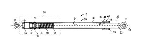
[0025] FIG. 1 is a schematic view of an actuator assembly;
[0026] FIG. 2 is a segmented schematic view of the actuator assembly having
a lost motion device and a sealing member; and
[0027] FIG. 3 is a view of the lost motion device of the actuator assembly.
DETAILED DESCRIPTION
[0028] A detailed description of one or more embodiments of the disclosed
apparatus and method are presented herein by way of exemplification and not
limitation with reference to the Figures.
[0029] Gas turbine engines may be disposed within a nacelle having a cowl or
an access door to enable ground maintenance personnel to service the gas
turbine
engine. The cowl or access door may be movable between an open position and a
closed position by a hydraulically operated door opening system. Referring to
FIGS.
1 - 3, the door opening system includes an actuator assembly 10. The actuator
assembly 10 may be a linear actuator assembly that is displaceable or
extensible along
an axis. The actuator assembly 10 includes a housing 20, a piston rod 22, a
sealing
member 24, and a lost motion device 26.
[0030] The housing 20 extends along a first axis 30 between a first housing
end 32 and a second housing end 34. The housing 20 defines a housing bore 36
that
extends from the first housing end 32 towards the second housing end 34. The
housing 20 is configured as a hollow member such that the first housing end 32
is
4
CA 3021496 2018-10-18
configured as an open end and the second housing end 34 is configured as a
closed
end.
[0031] Referring to FIGS. 2 and 3, the first housing end 32 includes a flared
portion 40. The flared portion 40 has a cross-sectional diameter or cross-
sectional
form that is greater than a cross-sectional diameter or cross-sectional form
of the
remainder of the housing 20 that extends between the first housing end 32 and
the
second housing end 34. A portion of the housing bore 36 proximate the flared
portion
40 includes a stepped region 42. The stepped region 42 extends between a
proximal
end 44 of the flared portion 40 towards a distal end 46 of the flared portion
40. The
stepped region 42 includes a first stepped surface 48 and a second stepped
surface 50.
The first stepped surface 48 extends from the first housing end 32 towards the
second
stepped surface 50. The second stepped surface 50 extends from the first
stepped
surface 48 towards the distal end 46 of the flared portion 40. In at least one
embodiment, a shoulder 52 extends between the first stepped surface 48 and the
second stepped surface 50.
[0032] As shown in FIGS. 1 and 2, a stop member 54 is disposed within the
housing bore 36 and is disposed proximate the second housing end 34. The stop
member 54 may be defined by the housing 20 and extend into the housing bore 36
proximate the second housing end 34.
[0033] Referring to FIGS. 1 -3, the housing 20 may include or define a first
mounting feature 56. The first mounting feature 56 may be configured as an eye
or
yoke that may be attached to a component of the gas turbine engine or may be
attached to a ground service cart.
[0034] The piston rod 22 is at least partially disposed within the housing
bore
36. The piston rod 22 extends along the first axis 30 between a first piston
end 60 and
a second piston end 62. The piston rod 22 has a rod diameter or cross-
sectional rod
form.
CA 3021496 2018-10-18
[0035] The piston rod 22 is movably disposed within the housing 20 such that
while the actuator assembly 10 is in a first position (retracted position or
non-
extended position) the first piston end 60 is disposed proximate the second
housing
end 34 and while the actuator assembly 10 is in a second position (extended
position
or non-retracted position) the first piston end 60 is spaced apart from the
second
housing end 34 or is disposed closer to the first housing end 32 as compared
to the
first position.
[0036] Referring to FIGS. 1 and 2, the piston rod 22 defines a piston bore 64
that extends from the first piston end 60 towards the second piston end 62
along the
first axis 30. The piston rod 22 is configured as a hollow member such that
the first
piston end 60 is configured as an open end and the second piston end 62 is
configured
as a closed end.
[0037] The second piston end 62 may include or define a second mounting
feature 66. The second mounting feature 66 is integrally formed with the
piston rod
22. The second mounting feature 66 may be configured as an eye or yoke that
may be
attached to a movable component of the gas turbine engine such as a cowl, a
door, an
access panel, or the like. The second piston end 62 having the second mounting
feature 66 may move relative to the first housing end 32 to move the movable
component of the gas turbine engine between an open position and a closed
position
based on actuation of the actuator assembly 10.
[0038] The sealing member 24 is disposed about the piston rod 22 proximate
the second piston end 62. The sealing member 24 is disposed within and is
engaged
with the housing bore 36 proximate the first housing end 32. More
specifically, the
sealing member 24 is disposed within the stepped region 42 and engages the
second
stepped surface 50 of the housing bore 36.
[0039] The sealing member 24 includes a sealing member body 70 and a
sealing member flange 72. The sealing member body 70 is at least partially
disposed
within the stepped region 42 of the housing bore 36.
6
CA 3021496 2018-10-18
[0040] The sealing member body 70 includes a first protrusion 80, a second
protrusion 82, and a notch 84. The first protrusion 80 and the second
protrusion 82
are axially spaced apart from each other, with respect to the first axis 30.
The first
protrusion 80 and the second protrusion 82 radially extend from the sealing
member
body 70, with respect to the first axis 30, and engage the second stepped
surface 50 of
the housing bore 36. The notch 84 is disposed proximate an end of the sealing
member body 70 and is arranged to receive a seal that engages the piston rod
22.
[0041] The sealing member flange 72 extends from the sealing member body
70. The sealing member flanged 72 radially extends from the sealing member
body
70 and engages the distal end 46 of the flared portion 40 of the housing 20.
The
sealing member flange 72 is a cross-sectional diameter or cross-sectional form
that is
greater than a cross-sectional diameter or cross-sectional form of the flared
portion 40
of the housing 20.
[0042] Referring to FIGS. 1-3, the lost motion device 26 is at least partially
disposed within the housing bore 36 and extends into the piston bore 64. The
lost
motion device 26 is disposed proximate the second housing end 34 and the first
piston
end 60. The lost motion device 26 is operatively connected to the piston rod
22 and is
arranged to move relative to the housing 20 along the first axis 30 between
the first
position and the second position with the piston rod 22.
[0043] The lost motion device 26 includes a slider 90, a bearing member 92, a
first spring seat 94, a second spring seat 96, and a biasing member 98.
[0044] Referring to FIGS. 2 and 3, the slider 90 is movably or slidably
connected to the piston rod 22 proximate the first piston end 60. The slider
90
includes a head 100 and a neck 102 that extends from the head 100.
[0045] The head 100 is an enlarged head that is slidably engaged with the
housing bore 36 and is disposed proximate the second housing end 34 while the
actuator assembly 10 is in the first position. The head 100 has a head
diameter that is
7
CA 3021496 2018-10-18
greater than the rod diameter, in other words, the rod diameter is less than
the head
diameter.
[0046] The head 100 extends between a first head end 110 and a second head
end 112 along the first axis 30. The first head end 110 may engage the stop
member
54 while the actuator assembly 10 is in the first position. The second head
end 112 is
spaced apart from the stop member 54 and is disposed proximate the first
piston end
60. The head 100 defines a first bearing ring groove 114 that is disposed
proximate
the first head end 110 and a second bearing groove 116 that is disposed
proximate the
second head end 112. Each of the first bearing ring groove 114 and the second
bearing groove 116 are arranged to receive a seal or a bearing ring.
[0047] The head 100 further includes or defines a first sealing projection 118
and the second sealing projection 120 that is axially spaced apart from the
first sealing
projection 118. The first sealing projection 118 and the second sealing
projection 120
engage the housing bore 36. A hydraulic sealing groove 122 is defined between
the
first sealing projection 118 and the second sealing projection 120. The
hydraulic
sealing groove 122 is arranged to receive a hydraulic seal 124 that engages
the
housing bore 36.
[0048] The neck 102 has a neck diameter that is less than the head diameter.
The neck 102 extends from the second head end 112 and extends into the piston
bore
64. The neck 102 extends between a first neck end 130 and a second neck end
132
along the first axis 30. In at least one embodiment, the first neck end 130 is
spaced
apart from and is not disposed within the piston bore 64.
[0049] The neck 102 defines at least one elongate opening 134 that is disposed
between the first neck end 130 and the second neck end 132. A pin 136 extends
along
a second axis 140 that is disposed transverse to the first axis 30. The pin
136 extends
through the first piston end 60 of the piston rod 22 and through the at least
one
elongate opening 134 to movably connect the slider 90 to the piston rod 22.
The
combination of the at least one elongate opening 134 and the pin 136 enables
the
8
CA 3021496 2018-10-18
slider 90 to move relative to the piston rod 22 at least until the pin 136
engages an end
of the at least one elongate opening 134.
[0050] The bearing member 92 is disposed about the piston rod 22 proximate
the first piston end 60. The bearing member 92 engages the housing bore 36.
The
bearing member 92 is proximately aligned with the pin 136 along the second
axis 140.
In at least one embodiment, the pin 136 at least partially extends into the
bearing
member 92.
[0051] The first spring seat 94 is fixedly positioned or fixedly disposed
within
the piston bore 64. The first spring seat 94 may be defined by a retaining
member that
is secured within the piston bore 64.
[0052] The second spring seat 96 is movably positioned or movably disposed
within the piston bore 64 and is axially spaced apart from the first spring
seat 94. The
second spring seat 96 may be defined by a retaining member that is disposed
within
the piston bore. The second spring seat 96 is disposed proximate and may abut
the
second neck end 132. In at least one embodiment, the second spring seat 96 may
be
defined by the second neck end 132 of the neck 102 and may not be a separately
provided component.
[0053] The biasing member 98 is disposed within the piston bore 64 and
extends between and engages the first spring seat 94 and the second spring
seat 96.
Biasing member 98 biases the slider 90 towards the second housing end 34. The
biasing member 98 is arranged or positioned to compress or extend responsive
to
movement of the slider 90 along the first axis 30 relative to the piston rod
22. The
biasing member 98 of lost motion device 26 absorbs, damps, or dissipates
vibrations
or push and pull motion to protect the dynamic hydraulic sealing provided by
the
various sealing features of the actuator assembly 10 to prevent leaks or water
intrusion.
9
CA 3021496 2018-10-18
[0054] The term "about" is intended to include the degree of error associated
with measurement of the particular quantity based upon the equipment available
at the
time of filing the application.
[0055] The terminology used herein is for the purpose of describing particular
embodiments only and is not intended to be limiting of the present disclosure.
As
used herein, the singular forms "a", "an" and "the" are intended to include
the plural
forms as well, unless the context clearly indicates otherwise. It will be
further
understood that the terms "comprises" and/or "comprising," when used in this
specification, specify the presence of stated features, integers, steps,
operations,
elements, and/or components, but do not preclude the presence or addition of
one or
more other features, integers, steps, operations, element components, and/or
groups
thereof.
[0056] While the present disclosure has been described with reference to an
exemplary embodiment or embodiments, it will be understood by those skilled in
the
art that various changes may be made and equivalents may be substituted for
elements
thereof without departing from the scope of the present disclosure. In
addition, many
modifications may be made to adapt a particular situation or material to the
teachings
of the present disclosure without departing from the essential scope thereof.
Therefore, it is intended that the present disclosure not be limited to the
particular
embodiment disclosed as the best mode contemplated for carrying out this
present
disclosure, but that the present disclosure will include all embodiments
falling within
the scope of the claims.
CA 3021496 2018-10-18