Note: Descriptions are shown in the official language in which they were submitted.
CA 03021860 2018-10-22
WO 2017/184153 PCT/US2016/028671
DIAMETRICALLY ADJUSTABLE ENDOPROSTHESES AND ASSOCIATED
SYSTEMS AND METHODS
BACKGROUND
[0001] Various bodily lumens, including those of the body's various
circulatory systems,
are sensitive to internal fluid pressures. For example, it is known that
diseased or damaged liver
tissue may increase the resistance to hepatic perfusion resulting in excessive
and often dangerous
fluid pressure increases in the portal vascular circulation. This condition
can lead to
gastrointestinal variceal hemorrhage and pathological conditions such as
ascites.
[0002] In order to decompress the portal circulation, a transjugular
intrahepatic
portosystemic shunt (TIPS) may be created through the liver tissue by
connecting the portal vein
to the inferior vena cava via the hepatic vein. This procedure includes
forming a pathway
directly through the liver to allow direct flow between the portal vein and
the hepatic vein. In
some treatment methods, the pathway is maintained and lined with a stent or
stent-graft to form a
shunt. The TIPS procedure has proven to be safe and effective at decompressing
the portal
system and in controlling acute variceal hemorrhage, for example.
[0003] U.S. Patent 6,673,102 to Vonesh et al. describes endovascular
devices for use in
transjugular intrahepatic portosystemic shunt (TIPS) procedures, including
devices that employ a
two-part stent-graft construction that provides a low permeability membrane to
line the shunt and
an uncovered stent portion designed to reside in the portal vein. The devices
provide numerous
features, including having a compact delivery profile, being easy to
accurately deploy, and
incorporation of resistance to tissue and bile ingress.
SUMMARY
[0004] This disclosure provides diametrically adjustable endoprosthesis
designs and
associated systems and methods that incorporate various advantages, including
the ability to
adjust endoprosthesis diameter, and thus achieve desirable fluid flow and
fluid pressures across
the endoprostheses. In various implementations, the endoprostheses include
controlled expansion
elements coupled to grafts or stent-grafts. In some designs including self-
expanding stent-grafts,
one or more controlled expansion elements diametrically constrain and limit
expansion of the
self-expanding stent-grafts following initial deployment. The stent-grafts
self-expand to an
initial diameter and can be mechanically altered over a range of diameters due
to the constraining
elements being able to maintain the adjusted diameter under physiologic
conditions. Following
initial deployment, the stent-grafts are capable of being further
diametrically expanded, for
example using balloon dilation. In various implementations, these subsequent,
diametric
1
CA 03021860 2018-10-22
WO 2017/184153 PCT/US2016/028671
adjustments are achieved by mechanically altering (e.g., plastically
deforming) the controlled
expansion elements beyond the initial diameters set by the controlled
expansion elements. Once
altered, the controlled expansion elements are configured to reliably maintain
the adjusted
diameter at physiologic conditions. In some designs, the stent-grafts have
maximum diametric
expansion limits (e.g., the as manufactured diameters) that define the upper
ends of the ranges to
which the endoprostheses can be adjusted, such that diametric adjustments can
be made from the
initial diameter up to the maximum designed stent-graft diameter.
[0005] Some embodiments relate to a diametrically adjustable endoprosthesis
including a
stent-graft and a controlled expansion element. The stent-graft includes a
stent and a base graft
secured to the stent. The base graft has a first end and a second end and the
stent-graft is self-
expanding and exhibits a self-expansion force. The stent-graft has a maximum
diametric
expansion limit. The controlled expansion element has a continuous wall and an
initial diametric
expansion limit. The controlled expansion element is adjustable to an adjusted
diameter in a
range of diameters between the initial diametric expansion limit and the
maximum diametric
expansion limit when placed under an expansion force in addition to that of
the self-expansion
force of the stent-graft. The controlled expansion element is configured to
maintain the adjusted
diameter under physiological conditions following removal of the expansion
force and the stent-
graft is configured to limit the range of diameters for the adjusted diameter
to the maximum
diametric expansion limit.
[0006] In some methods of treatment, following initial deployment and
seating of an
endoprosthesis, a user (e.g., clinician) obtains one or more fluid pressure
measurements from the
circulatory system into which the endoprosthesis is placed. The user is then
able to adjust
system pressure by adjusting the diameter of the endoprosthesis, the
endoprosthesis being
configured to maintain the adjusted-to diameter. Such measurements and
adjustments may occur
at the time of initial implantation, or as part of another procedure performed
hours, days, weeks,
or even years later. In some methods of treatment, the user can predetermine
(e.g., prior to initial
implantation) that a diametric adjustment will be desired and make the desired
diametric
adjustment at the time of implantation.
[0007] Some examples of treatments benefiting from this adjustability
feature include
intrahepatic portosystemic shunts. Intrahepatic portosystemic shunts are
commonly performed
endoluminally through the jugular vein, connecting the portal vein to the
inferior vena cava by
way of the hepatic vein. Such a procedure is commonly referred to as being a
"transjugular
intrahepatic portosystemic shunt" or abbreviated "TIPS" or "TIPS S." It should
be appreciated,
however, that a shunt through the liver between the portal vein and the vena
cava may be
2
CA 03021860 2018-10-22
WO 2017/184153 PCT/US2016/028671
accomplished by other methods. As such, the term "intrahepatic portosystemic
shunt" as used
herein is intended to include any procedure whereby pressure is relieved in
the portal vein by
way of a shunt from the portal to the systemic systems. Additionally, the
instant disclosure
describes various advantages of endoprosthesis designs and associated
treatment methods for
forming intrahepatic portosystemic shunts by way of example, although it
should be appreciated
the various concepts are also applicable to other types of treatments, such as
providing
diametrical reserve for treatment of endoleaks, gall bladder drainage,
pediatric shunts, fistulas,
AV access, for sealing of side branch devices, and for allowance for future
lumen narrowing and
adjustability to custom fit to tapered anatomy, among others.
[0008] Some embodiments relate to a method of forming an intrahepatic
portosystemic
shunt. The method includes positioning an endoprosthesis in a liver of a
patient at a delivery
diametrical dimension, the endoprosthesis comprising a self-expanding stent-
graft and a
controlled expansion element. The endoprosthesis is deployed such that the
endoprosthesis self-
expands and is seated in the liver of the patient to form an intrahepatic
portosystemic shunt, the
controlled expansion element limiting expansion of a diametrically controlled
portion of the
endoprosthesis to an initial deployed diametrical dimension such that the
initial deployed
diametrical dimension is maintained under physiologic conditions. An internal
pressure is
applied to the endoprosthesis after deploying the endoprosthesis such that at
least a portion of the
controlled expansion element is mechanically altered and the diametrical
dimension of the
diametrically controlled portion of the endoprosthesis is selectively enlarged
to an enlarged
diametrical dimension and maintained at the enlarged diametrical dimension
under physiologic
conditions.
[0009] Some embodiments relate to a method for treating portal
hypertension. The method
includes providing an endoprosthesis including a stent, a first graft portion,
and a second graft
portion extending along at least a portion of the first graft portion, the
endoprosthesis being
constrained to a first diametrical dimension by a delivery constraint for
insertion into a lumen
and configured to self-expand to a second enlarged diametrical dimension when
the delivery
constraint is released, the second graft portion defining a diametrically
controlled portion of the
endoprosthesis that is restricted from further diametrical enlargement by self-
expansion to a
restricted diameter. The endoprosthesis is positioned in the portal vein and
the hepatic vein. The
endoprosthesis is deployed to the second enlarged diametrical dimension by
releasing the
delivery constraint and allowing the endoprosthesis to self-expand, the
diametrically controlled
portion maintaining the restricted diameter under physiologic conditions. A
diametric
adjustment of the endoprosthesis is performed in situ, including diametrically
expanding at least
3
CA 03021860 2018-10-22
WO 2017/184153 PCT/US2016/028671
a portion of the diametrically controlled portion of the endoprosthesis to an
adjusted diameter by
applying distending force to the diametrically controlled portion of the
endoprosthesis, the
diametrically controlled portion of the endoprosthesis maintaining the
adjusted diameter under
physiologic conditions.
[0010] Some embodiments relate to a method for treating portal hypertension
including
taking at least one pressure measurement to determine a pressure gradient
resulting from a shunt
formed by an endoprosthesis between the portal vein and the systemic venous
circulation at least
24 hours after formation of the shunt. The endoprosthesis includes a self-
expanding stent having
at least a first segment and a second segment, a graft component on the first
segment, at least a
portion of the graft component being maintained at an initial deployment
diameter by a
controlled expansion element that is mechanically adjustable, and
diametrically expanding the
controlled expansion element by mechanically adjusting the controlled
expansion element with a
distensive force such that at least a portion of the graft component being
maintained at the initial
deployment diameter by the controlled expansion element is enlarged and
maintained at an
enlarged diameter by the controlled expansion element to reduce the pressure
gradient.
[0011] Some embodiments relate to methods of making endoprostheses. Some
embodiments include securing a stent to a base graft to form a stent-graft,
positioning a
controlled expansion element along the stent-graft, and coupling the
controlled expansion
element to the stent-graft. The controlled expansion element can be an
intermediate layer within
the graft portion, an outermost layer outside of the graft portion, or an
innermost layer inside of
the graft portion. Additionally, multiple controlled expansion elements at any
of the foregoing
positions are contemplated. The controlled expansion element can be
incorporated into at least a
portion of the graft portion or underlay or overlay at least a portion of the
graft portion of the
endoprosthesis. The controlled expansion element can be coupled to the stent-
graft by adhesive
or mechanical fit for example, or by incorporating the controlled expansion
element into the graft
portion.
In some embodiments, the stent-graft and controlled expansion portion are
coupled by
mechanically adjusting the controlled expansion element from a first diameter
to the initial
diametric expansion limit, the first diameter being smaller than the initial
diametric expansion
limit. Some additional aspects of methods of making diametrically adjustable
endoprostheses
according to the instant disclosure include securing a stent that is self-
expanding to a base graft
to form a stent-graft, positioning a controlled expansion element having a
continuous wall about
a portion of the stent-graft, and coupling the controlled expansion element to
the stent-graft. In
some embodiments, coupling the controlled expansion element to the stent-graft
includes
4
CA 03021860 2018-10-22
WO 2017/184153 PCT/US2016/028671
mechanically adjusting the controlled expansion element to an initial
diametric expansion limit
corresponding to a diameter to which the endoprosthesis self-expands in an
unconstrained state.
[0012] In some instances, the base graft includes expanded PTFE having a
crystalline melt
temperature, and further wherein the controlled expansion element is coupled
to the stent-graft
component at a temperature that is less than the crystalline melt temperature.
Also, the
controlled expansion element is optionally coupled to the stent-graft
components such that the
controlled expansion element is able to change in longitudinal dimension
(e.g., longitudinally
contract during radial expansion) at a different rate than the stent-graft at
a sliding interface. For
example, one or more portions of the interface between the stent-graft and
controlled expansion
element are not bonded or otherwise attached in a manner that would prevent
differential
longitudinal contraction during expansion of the endoprosthesis.
[0013] While multiple embodiments are disclosed, still other embodiments of
the present
invention will become apparent to those skilled in the art from the following
detailed description,
which shows and describes illustrative embodiments of the invention.
Accordingly, the
drawings and detailed description are to be regarded as illustrative in nature
and not restrictive.
BRIEF DESCRIPTION OF THE DRAWINGS
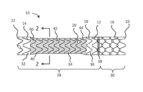
[0014] FIG. 1 shows a diametrically adjustable endoprosthesis, according to
some
embodiments.
[0015] FIG. 2 shows a cross-sectional view of the endoprosthesis of FIG. 1
taken along line
2-2 in FIG. 1, according to some embodiments.
[0016] FIG. 3 shows the endoprosthesis of FIG. 1 at an adjusted diameter,
according to
some embodiments.
[0017] FIGS. 4 and 5 show a portion of a delivery system for use with the
endoprosthesis of
FIG. 1, according to some embodiments.
[0018] FIG. 6 shows the endoprosthesis of FIG. 1 deployed in a patient,
according to some
embodiments.
[0019] FIG. 7 shows a schematic representation of a balloon expansion of
the
endoprosthesis, according to some embodiments.
[0020] FIG. 8 shows a controlled expansion element, according to some
embodiments.
DETAILED DESCRIPTION
[0021] FIG. 1 shows a diametrically adjustable endoprosthesis 10, according
to some
embodiments. As shown, the endoprosthesis 10 includes a stent 12, also
described as a stent
element or support. The stent 12 has a first segment 14 and a second segment
16. As shown, a
CA 03021860 2018-10-22
WO 2017/184153 PCT/US2016/028671
base graft 18, also described as a first graft portion, a cover or a liner, is
provided along the
length of the first segment 14, while a portion of the second segment 16
extends beyond the base
graft 18 and is left largely uncovered. The terms "graft," "cover," and
"liner" are used
interchangeably herein, and are not meant to require a certain relative
position with respect to the
stent 12. A "liner" may surround the stent 12, a "cover" may be received
entirely within the
stent 12, and a "lined region" corresponds to a portion of an endoprosthesis
including a graft
layer, regardless of whether the graft resides inside, outside, sandwiches, or
is otherwise
positioned relative to a stent element. The endoprosthesis 10 also includes a
controlled
expansion element 20, also described as a second graft portion. In FIGS. 1 and
3, the controlled
expansion element 20 is called out with cross-hatching in FIGS. land 3 for
ease of visualization.
The controlled expansion element 20 extends along at least a portion of the
base graft 18 and
optionally enhances or augments one or more functions of the base graft 18,
for example serving
as a functional graft component of the base graft 18. As shown, the
endoprosthesis 10 has a
proximal end 22 and a distal end 24 and defines an inner lumen 26 (FIG. 2). In
order to facilitate
placement of the endoprosthesis 10, radiopaque markers are provided along the
length of the
endoprosthesis 10 as desired.
[0022] As shown in FIG. 1, the assembled endoprosthesis 10 includes a graft-
lined region
28 and an unlined region 30, although in other designs the entire
endoprosthesis 10 is lined and
is characterized by an absence of an unlined region. In intrahepatic
portosystemic shunt
configurations, the graft-lined region 28 corresponds to an intrahepatic
region and the unlined
region 30 corresponds to a portal region. The graft-lined region 28 defines a
first end portion 32,
a middle portion 34, and a second end portion 36. The border between the graft-
lined region 28
and the unlined region 30 is indicated by a circumferential radiopaque gold
marker band 38
proximate, or just proximal to, the border. An additional radiopaque gold
marker is optionally
located on the proximal end 22 of the endoprosthesis 10.
[0023] The middle portion 34 of the graft-lined region 28, and in
particular the portion of
the endoprosthesis 10 corresponding to the controlled expansion element 20,
forms a
diametrically controlled portion of the endoprosthesis 10. As shown, the
diametrically
controlled portion of the endoprosthesis 10 (the middle portion 34 in FIG. 1),
extends for less
than an entire length of the endoprosthesis 10, and in particular less than a
full length of the
graft-lined region 28, although in other embodiments the controlled expansion
extends for any
desired length, including the full endoprosthesis length as desired.
[0024] As shown, the middle portion 34 corresponding to the controlled
expansion portion
of the endoprosthesis 10 has a first flared end 40, a central portion 42, and
a flared second end
6
CA 03021860 2018-10-22
WO 2017/184153 PCT/US2016/028671
44. The first and second flared ends 40, 44 taper in different directions and
at taper angle
relative to the longitudinal axis of the endoprosthesis 10 (e.g., at a
relative angle from about 10-
80 degrees, including any value therebetween, such as about 60 degrees).
Although the flared
ends 40, 44 are shown with generally linear tapers, curved tapers, re-curved
tapers, combined
linear and curved tapers, and others are contemplated. The first and second
flared ends 40, 44
help provide a smooth transition to the adjacent, first and second end
portions 32, 36 when the
endoprosthesis 10 is in an unconstrained state following initial deployment.
Although the central
portion 42 is shown as having a substantially uniform diameter, the central
portion 42 optionally
includes one or more tapers as desired, as can any of the other portions of
the endoprosthesis 10.
[0025] The middle portion 34 of the graft-lined region 28 is constrained
with the controlled
expansion element 20 such that the endoprosthesis 10 exhibits an initial
diametric expansion
limit at the middle portion 34 to which the endoprosthesis 10 is deployed and
which the
endoprosthesis maintains prior to one or more subsequent mechanical adjustment
steps. As
shown in FIG. 1, the expansion element 20 causes the middle portion 34 to take
on a dog-bone
shape or hourglass shape, although any of a variety of shapes are
contemplated. As shown in
FIG. 1, the endoprosthesis 10 defines a minimum inner diameter (ID) at a
boundary 46 between
the central portion 42 and the first flared end 40.
[0026] The diameter of the endoprosthesis 10 in the middle portion 34 is
smaller than the
adjacent portions of the endoprosthesis 10 because the controlled expansion
element 20
diametrically constrains self-expansion of the stent 12, but is able to be
mechanically adjusted by
a distensive force (e.g., using a balloon catheter) to allow diametric
adjustment. To that end, if
the controlled expansion element 20 was removed from the endoprosthesis 10 the
stent 12 and
base graft 18 would tend to self-expand to a maximum diametric expansion
limit. In particular,
the stent-graft 12, 18 is configured to expand to a maximum diameter (e.g.,
the manufactured
diameter of the stent-graft) at which point further expansion is significantly
resisted (e.g.,
resistance of 1000 ATM or more) and may even result in failure if an attempt
to force the stent-
graft 18 beyond that diameter is attempted. The stent 12, the graft 18, or the
combination of the
stent-graft 12, 18 can be configured to set this maximum diametric adjustment
limit, beyond
which the endoprosthesis 10 is not intended to be diametrically adjusted. In
the same way, if
balloon dilation is used to diametrically expand the controlled expansion
element 20, middle
portion 34 will expand correspondingly, up to a diameter of the adjacent,
first and second end
portions 32, 36 (e.g., as shown in FIG. 3) which represent the fully expanded
diameter of the
stent--graft 12, 18.
7
CA 03021860 2018-10-22
WO 2017/184153 PCT/US2016/028671
[0027] FIG. 3 shows the endoprosthesis 10 expanded to a maximum diametric
expansion
limit imparted by the remainder of the endoprosthesis 10, for example imparted
by the base graft
18. As shown, the lined region 28 has a maximum diametric expansion limit
corresponding to
the base graft 18 having a continuous cylindrical profile through the first
end portion 32, the
middle portion 34, and the second end portion 36. As previously referenced,
the stent-graft 12,
18 may have an "as manufactured" diameter, beyond which the stent-graft 12, 18
is not meant to
expand in typical use, whether under physiological conditions or by balloon
expansion.
[0028] In one example, the ID of the endoprosthesis 10 upon deployment at
the middle
portion 34 is approximately 8 mm and is expandable to approximately 10 mm. In
some
examples, the ID of the endoprosthesis 10 at the middle portion 34 (e.g., as
measured at the
minimum ID location 46) is expandable by 12% to 40%, for example. In still
other
embodiments, the endoprosthesis 10 at the middle portion 34 is expandable
greater than 40%,
such as up to 70% or even more.
[0029] For application in a TIPS procedure, the endoprosthesis 10 would
typically have
dimensions as follows: a length of about 5 to 12 cm, with a length of about 6
to 10 cm being
more typical; a deployed diameter of about 5 to 14 mm, with a diameter of
about 8 to 12 mm
being more typical; and a total wall thickness of about 0.1 to 1.0 mm, with
about 0.1 to 0.6 mm
being more typical. While the dimension "diameter" is used herein, it should
be understood that
this dimension is intended to define an average cross-sectional dimension and
is not intended to
limit designs to circular cross-sectional shapes. Moreover, as shown in FIG.
1, the
endoprosthesis 10 may be configured to exhibit multiple average cross-section
dimensions along
the length of the endoprosthesis 10, including tapers along different portions
of the
endoprosthesis 10.
[0030] In some embodiments, the endoprosthesis 10 itself has a compacted
dimension
suitable for endoluminal deployment, such as less than or equal to 16 French
(5.3 mm), although
a variety of dimensions are contemplated depending upon the treatment in which
it is applied. In
some embodiments, in order to be delivered percutaneously, the endoprosthesis
10 and its
deployment apparatus have a diameter of less than about 13 French (4.3 mm),
for example,
although a variety of dimensions are contemplated. "French" measurements as
used herein
define the size of a hole through which a device will pass. For example, a
device with a
measurement of "10 French" will pass through a 10 French hole (which has a
diameter of 3.3
mm). Again, the device need not have a circular cross-section in order to pass
through a circular
French hole so long as the hole is large enough to accommodate the widest
cross-sectional
dimension of the endoprosthesis 10.
8
CA 03021860 2018-10-22
WO 2017/184153 PCT/US2016/028671
[0031] The first segment 14 of the endoprosthesis 10 will typically
comprise about 50 to 90
percent of the entire length of the endoprosthesis 10. Accordingly, the first
segment 14 will
typically be about 4 to 8 cm in length and the second segment 16 will
typically be about 1 to 3
cm in length, although a variety of dimensions are contemplated. The middle
portion 34 of the
graft lined region 28 corresponding to the controlled expansion element 20
typically has a total
length of about 1 to 11.5 cm, where the first flared end 40 has a length of
about 0.25 to 1.5 cm,
more typically 0.5 cm, the central portion 42 has a length of about 0.5 to 8.5
cm, with 1.5 to 5.5
cm being more typical, and the flared second end 44 has a length of about 0.25
to 1.5 cm, with
0.5 cm being more typical, although a variety of dimensions are contemplated.
[0032] The stent 12 optionally includes any number of segments and
configurations,
according to various embodiments. As shown in FIG. 1, the first segment 14 has
an undulating,
helical stent pattern, although other configurations are contemplated. In
turn, the second
segment 16 optionally employs a different stent pattern from that of the first
segment 14. For
example, the second segment 16 is shown with an interlocked (or "chain-
linked") stent pattern
that helps prevent the second segment 16 from excessively longitudinally
elongating beyond a
predetermined desired length, although other configurations are contemplated.
In some
interlocked designs, a single wire is employed for the second segment 16,
where the wire is
wrapped from the cover 18 to a distal end 24 of the endoprosthesis 10 and then
back to the cover
18 such that the wire terminates within the cover 18 and avoids having a loose
end of the wire
exposed at the distal end 24 of the endoprosthesis 10.
[0033] In some methods of forming the interlocked (or "chain-linked") stent
pattern of the
second segment 16 a single wire is wrapped from the first segment 14 to the
distal end 24 of the
endoprosthesis 10 and then back to the first segment 14. Along the length of
the second segment
16 the wire is provided with a second undulated pattern along a first pass and
a third undulating
pattern, interlocking with the second undulating pattern along a second pass.
By interlocking the
second undulating pattern and the third undulating pattern, the stent pattern
permits the second
segment 16 to be longitudinally compressed, thus imparting flexibility; but
the stent pattern
prevents the second segment 16 from being longitudinally elongated beyond a
predetermined
maximum length. It should be noted that the interlocked stent pattern also
imparts columnar
support when the device is in a radially compressed configuration and less so
when it is
deployed. Examples of suitable stent patterns and associated methods of
manufacture for the
first and second segments are also described in U.S. Patent 6,673,102 to
Vonesh et al.
[0034] The first and second segments 14, 16 of the stent 12 may be formed
from a variety of
wire materials, including stainless steel, nickel-titanium alloy (nitinol),
tantalum, elgiloy, various
9
CA 03021860 2018-10-22
WO 2017/184153 PCT/US2016/028671
polymer materials, such as poly(ethylene terephthalate) (PET) or
polytetrafluoroethylene
(PTFE), or bioresorbable materials, such as levorotatory polylactic acid (L-
PLA) or polyglycolic
acid (PGA). In various examples, the stent 12 is self-expanding and exerts a
self-expansion
force on the endoprosthesis 10 when constrained. As such, in various designs
the first and
second segments 14, 16 of the stent 12 are formed of superelastic materials,
such as nitinol
metal, that will withstand tight compression in a compacted configuration
(diameter) and then
self-expand to a deployed configuration (diameter) once released in place,
such as those
described in U.S. Patent 6,673,102 to Vonesh et al.
[0035] Although the endoprosthesis 10 is generally described as including a
self-expanding
stent 12, it should be understood that the stent 12 may include one or more
balloon expandable
portions (e.g., the second segment 16 may be balloon expandable) or the entire
stent 12 may be
balloon expandable with the endoprosthesis 10 being free of any self-expanding
stent
components. For example, the controlled expansion element 20 is optionally
employed with a
balloon expandable stent-graft and allows diametric adjustment beyond an
initial deployment
diameter through a plurality of adjusted diameters up to a maxim diametric
expansion limit of
the balloon expandable stent-graft.
[0036] In general terms, the cover 18 helps provide the endoprosthesis 10
with a flow
lumen. In intrahepatic shunt applications, the cover 18 performs a number of
functions in the
endoprosthesis 10, including preventing extrusion of liver tissue through the
stent 12,
maintaining the maximum diametric dimensions of the endoprosthesis 10,
preventing
uncontrolled elongation of the stent 12, reducing or eliminating bile from
permeating into the
shunt, and facilitating bending without kinking, for example. As previously
described, the
controlled expansion element 20 optionally enhances or augments one or more
functions of the
base graft 18 beyond diametric adjustability. For example, the controlled
expansion element 20
optionally provides enhanced impermeability performance, longitudinal
strength, or others.
[0037] As shown in FIG. 2, the preferred material for the base graft 18
includes a base tube
48a, an inner film 48b, and an outer film 48c. The base tube 48a may be a
fluoropolymer
material and especially expanded polytetrafluoroethylene (PTFE). The inner
film 48b is also
optionally a fluoropolymer, and especially expanded PTFE. For example, the
base tube 48a may
be an extruded, thin-walled expanded PTFE base tube and the inner film 48b a
plurality of layers
of expanded PTFE film helically wrapped over the base tube. The outer film 48c
is also
optionally a fluoropolymer, such as a porous composite film of FEP and
expanded PTFE.
Examples of suitable materials for base tube 48a, inner film 48b, and outer
film 48c are
described in U.S. Patent 6,673,102 to Vonesh et al. As shown, the base graft
18 is substantially
CA 03021860 2018-10-22
WO 2017/184153 PCT/US2016/028671
continuous and uninterrupted in that the wall does not have any apertures or
holes of sufficient
size to remain patent in vivo, although grafts 18 with apertures or openings
(not shown)
configured to remain patent in vivo are also contemplated in other
applications. The inner and/or
outer film layers 48b, 48c optionally lend increased radial, or hoop strength
to the base graft 18
and help to set the maximum diametric expansion limit of the stent-graft 12,
18 at the as
manufactured diameter of the stent-graft 12, 18.
[0038] The stent 12 and the base graft 18 are secured together to provide a
stent-graft 12,
18. For example, the first segment 14 is secured to the base graft 18 and an
end of the second
segment 16 is optionally secured to the base graft 18 and/or first segment 14.
As shown, one or
more layers of the base graft 18 is positioned interior of the stent 12 to
define the inner lumen 26,
although the base graft 18 is optionally positioned entirely outside of the
stent element 12 or with
the stent 12 embedded into the base graft 18, for example. As shown, a
majority of the second
segment 16 of the stent 12 is left uncovered, with an end of the second
segment 16 secured to the
base graft 18 (e.g., a single "row") and a remainder of the second segment 16
extending from the
base graft 18. As shown, none of the interstices of the second segment 16 are
covered such that
fluid is able to flow through the interstices. In an intrahepatic shunt
application, the second
segment 16 is left uncovered to facilitate perfusion of portal venous branches
via blood flow
through the interstices of the second segment 16.
[0039] The base graft 18 is preferably attached to the stent 12 by bonding
or otherwise
attaching the two together through use of a suitable adhesive, such as
fluorinated ethylene
propylene (FEP), polyurethane, cyanoacrylates, or others. Additionally, the
materials may be
bonded or otherwise attached together through heat treatment (such as,
sintering of the materials
together) or through use of a wrap (for instance a tube, tape, or membrane)
around the outside of
the stent and cover (either continuous or discontinuous) that is adhered
through either a
thermoplastic or thermoset adhesive to the stent and cover. Alternatively, the
stent 12 may also
be coated with a thermopolymer or thermoset adhesive and the cover bonded or
otherwise
attached by reflowing or setting the polymer coating. In still other
embodiments, the stent 12
and base graft 18 are mechanically attached (e.g., using sutures).
[0040] In some methods of making the endoprosthesis 10, the stent 12 is
positioned as
desired over a portion of the base graft 18 (e.g., over a base tube and layers
of wrapped expanded
PTFE) and a porous composite film of FEP and expanded PTFE is wrapped over the
construction with the side of the film containing FEP toward the lumen of the
base graft 18. The
first segment 14 of the stent 12 is optionally coated with an adhesive, such
as FEP, placed around
the base tube 48a and inner film 48b, and is in turn covered by the outer film
48c. The assembly
11
CA 03021860 2018-10-22
WO 2017/184153 PCT/US2016/028671
can then be heated at one or more points in the assembly process to bond or
otherwise attach the
various layers together as described in U.S. Patent 6,673,102 to Vonesh et al.
[0041] In some embodiments, the controlled expansion element 20 is
configured to be
mechanically adjustable under pressure greater than typical biological
pressures (e.g., typically
circulatory pressures) and any expansion force exerted by the stent 12. For
example, the
controlled expansion element 20 is optionally mechanically adjustable by
causing controlled
expansion material forming one or more portions of the element 20 to yield or
plastically
deform, by causing reorganization of a fibrillary or other microstructure of
such controlled
expansion material, by release of fasteners or folds of the element 20, or
other mechanical
adjustment of the controlled expansion element 20. The pressure required to
mechanically adjust
the controlled expansion element 20 is greater than typical physiologic
conditions (e.g., typical
maximum blood pressures) such that the controlled expansion element 20 is able
to maintain the
adjusted diameter at less than a pressure that would tend to cause the stent-
graft 12, 18 to
catastrophically fail by exceeding the maximum diametric expansion limit of
the stent-graft 12.
The controlled expansion element 20 is preferably configured to maintain a
diameter to which it
is mechanically adjusted without substantial diameter creep or spontaneous
diametric expansion
over time under typical biological conditions. The controlled expansion
element 20 optionally
includes one or more layers and may be formed from a variety of materials,
including
fluoropolymer materials such as the distensible, expanded PTFE tube described
in U.S. Patents
3,953,556, 3,962,153, 4,096,227, 4,187,390, and 4,902,423, to Gore or the
distensible lattices of
U.S. 2013/0204347 to Armstrong, et al.
[0042] In some embodiments, the controlled expansion element 20 is formed
of controlled
expansion material including a bilayer compressed composite material formed of
layers each
including unsintered expanded PTFE and a stabilizing layer, such as a
continuous layer of FEP.
In some embodiments, the unsintered aspect of the expanded PTFE contributes to
the
expandability of the controlled expansion material. Unsintered expanded PTFE
can be
manufactured by extrusion followed by concurrent heating and stretching.
Sintered expanded
PTFE is manufactured by extrusion, concurrent heating and stretching, and
sintering (heating to
above the PTFE crystalline melting point temperature). Because unsintered
expanded PTFE is
heated to a lesser extent than sintered expanded PTFE, unsintered expanded
PTFE material has
greater conformability and greater stretchability than sintered expanded PTFE.
The unsintered
expanded PTFE has nonbent fibrils that can elongate approximately 40% or more
before rupture,
for example.
12
CA 03021860 2018-10-22
WO 2017/184153 PCT/US2016/028671
[0043] In some methods of manufacture, one or more wraps of the unsintered
expanded
PTFE/FEP composite material are overlapped to comprise the controlled
expansion element 20.
The FEP bonds together the multiple wraps of unsintered expanded PTFE to
create a monolithic
sleeve structure, for example, although a variety of configurations are
contemplated (e.g., rings,
collars, cylinder segments). For example, the controlled expansion element is
optionally formed
by cutting the unsintered and compressed, or densified, controlled expansion
material into strips
that are helically wound onto a cylindrical mandrel. One or more layers are
formed in one or
more passes to form a sleeve. In some embodiments, the material is wound so
that the FEP side
of the controlled expansion material faces outward. Any number of additional
layers (e.g., an
attachment or bonding layer) may also be applied over the controlled expansion
element 20 as
desired at any point in the process of forming the controlled expansion
element 20 and/or during
assembly of the endoprosthesis 10. The diameter of the cylindrical mandrel
determines the
initial inner diameter of the controlled expansion element 20.
[0044] In some methods, the controlled expansion element 20 is then heated,
while still on
the mandrel, to activate the FEP adhesive. The heat causes the FEP to flow,
thereby creating a
functionally unitary multi-layered sleeve of unsintered expanded PTFE. After
cooling, the
controlled expansion element 20 is removed from the mandrel and the ends of
the controlled
expansion element 20 are trimmed to create a sleeve of a desired length. The
controlled
expansion element 20 also optionally has a substantially continuous and
uninterrupted wall
characterized by the absence of apertures or holes configured to remain patent
in vivo.
[0045] In some methods of assembly, the controlled expansion element 20 is
placed onto an
underlying portion of the endoprosthesis 10, such as the stent 12 and base
graft 18 (collectively,
"stent-graft 12, 18"), although a variety of configurations are contemplated,
including the
controlled expansion element 20 being secured inside of the stent-graft 12,
18. In some methods
of assembly, the pre-assembled stent-graft 12, 18 is pulled through a loading
funnel and into a
tube with an outer diameter that is smaller than the inner diameter of the
controlled expansion
element 20. The tube containing the stent-graft 12, 18 is placed within the
controlled expansion
element 20 and the tube is removed from the stent-graft 12, 18. Upon emergence
from the tube,
the stent-graft 12, 18 self-expands to conform to the inner diameter of the
controlled expansion
element 20. As shown in FIG. 1, the controlled expansion element 20 has a
length selected to be
shorter than the base graft 18 such that a partial segment of the base graft
18 corresponding to
the middle portion 34 is covered by the controlled expansion element 20.
[0046] In some embodiments, the controlled expansion element 20 is coupled
to a portion of
the remaining endoprosthesis 10 mechanically (e.g., by interference fit,
friction fit, sutures, or
13
CA 03021860 2018-10-22
WO 2017/184153 PCT/US2016/028671
others). In other embodiments, the controlled expansion element 20 is
alternatively or
additionally secured to the endoprostheses using a bonding agent (e.g., an
adhesive such as FEP)
between the endoprosthesis and the controlled expansion element 20. The
bonding agent is
optionally applied as a continuous layer or a discontinuous layer over
substantially all the
interface between the controlled expansion element 20 and the remaining
endoprosthesis 10 or
over only one or more portions of the interface between the controlled
expansion element 20 and
the remaining endoprosthesis 10. Though less desirable in controlled expansion
elements 20 in
which it is desirable for the material to remain unsintered, in some
embodiments the controlled
expansion element 20 is alternatively or additional coupled to the graft by a
heating operation
(e.g., by a global sintering or localized sintering at one or more selected
portions of the interface
between the controlled expansion element 20 and the remaining endoprosthesis
10).
[0047] In some embodiments, an inner diameter set process is performed for
coupling the
controlled expansion element 20 to the stent-graft 12, 18 prior to collapsing
the endoprosthesis
into a delivery configuration. Some set processes include pulling the stent-
graft 12, 18 with
controlled expansion element 20 placed on it over a mandrel (not shown) having
a larger outer
diameter than the initial ID of the assembled endoprosthesis 10. The mandrel
has an outer
diameter (OD) corresponding to the shape of the middle portion 34 and the
desired initial
diametric expansion limit of the endoprosthesis 10 (the ID to which the
endoprosthesis self-
expands to in vivo following deployment prior to mechanically adjusting the
controlled
expansion element 20). For example, in an endoprosthesis adjustable between 8-
10 mm, the
controlled expansion element 20 would cause the endoprosthesis 10 to have an
ID less than 8
mm and the OD of the mandrel would be 8 mm such that after the set process the
controlled
expansion element 20 is mechanically adjusted and the endoprosthesis 10
exhibits an 8 mm ID.
In some embodiments, the mandrel has flared ends corresponding to the ends of
the controlled
expansion element 20 to provide flared ends to the controlled expansion
element 20 and a
smoother transition between the segment of the stent-graft 12, 18 constrained
by the controlled
expansion element 20 and adjacent segments of the stent graft 12, 18. Although
the mandrel
may have a continuous diameter between flared ends, any number of flares,
tapers, curves, or
other features are contemplated for imparting corresponding features to the
portion of the
endoprosthesis 10 corresponding to the controlled expansion element 20.
[0048] The set process causes the controlled expansion element 20 to
conform to the outer
surface of the endoprosthesis 10, which is believed to help hold the
controlled expansion element
in place through subsequent processing, deployment, and implantation of the
endoprosthesis
10 without the use of thermal and/or adhesive bonding. In some embodiments,
the absence of
14
CA 03021860 2018-10-22
WO 2017/184153 PCT/US2016/028671
thermal and/or adhesive bonding or other attachment along at least a portion
of the interface
between the controlled expansion element 20 and the stent-graft 12, 18 defines
a sliding interface
that helps allow the controlled expansion element 20 to slide on the surface
of the stent-graft 12,
18 when ballooned, thus limiting the amount of foreshortening the controlled
expansion element
20 translates to the stent-graft 12, 18. For example, an interference fit
between the stent graft 12,
18 and controlled expansion element 20 provides a sliding interface between
the components,
according to some embodiments. In different terms, during diametric expansion
of the
endoprosthesis 10, the sliding interface between the controlled expansion
element 20 and the
stent-graft 12, 18 permits at least a portion of the controlled expansion
element 20 to change in
longitudinal dimension (e.g., contract during radial expansion) at a different
rate than the stent-
graft 12, 18 at the sliding interface.
[0049] In some other embodiments, a portion of the interface between the
controlled
expansion element 20 and stent-graft 12, 18 is adhesively bonded. For example,
in some
embodiments a fluoropolymer adhesive is used, such as tetrafluoroethylene
(TFE) and
perfluoromethyl vinyl ether (PMVE) described in U.S. Patent 7,462,675 to Chang
et al., FEP
(fluorinated ethylene propylene), or PFA (perfluoroalkylvinyl
ether/tetrafluoroethylene
copolymer), for example. The adhesive is optionally applied on the inner
diameter of the
controlled expansion element 20, for example at each end of the controlled
expansion element 20
but not at the central region, although a variety of configurations are
contemplated. After the
controlled expansion element 20 is placed on the stent-graft 12, 18 the
adhesive is activated by
applying heat thereto, for example without causing sintering, or at least
without causing
significant sintering, of the controlled expansion material 20.
[0050] In still other embodiments, the controlled expansion element 20 is
adhered along the
entire interface or a majority of the interface the controlled expansion
element 20 forms with the
remaining endoprosthesis 10. For example, in some embodiments including a
controlled
expansion element having an outer layer of FEP, the controlled expansion
element 20 is everted
prior to applying it over the stent-graft 12, 18. The eversion of the
controlled expansion element
20 repositions the FEP that was previously on the outer diameter (abluminal
surface) of the
controlled expansion element 20 to the inner diameter (luminal surface). FIGS.
4 and 5 illustrate
a distal portion of a delivery system 50 for delivering and deploying the
endoprosthesis 10 to a
desired location for treatment, according to some embodiments. The delivery
system 50 is a
catheter-based, multi-staged deployment system including various features such
as those
described in U.S. Patent 6,673,102 to Vonesh et al. As shown, the delivery
system 50 includes
an introducing (or packaging) constraint 52, a delivery constraint 54, a
distal catheter shaft 56,
CA 03021860 2018-10-22
WO 2017/184153 PCT/US2016/028671
and a proximal catheter shaft 58 (partially shown and extending proximally in
FIGS. 4 and 5).
FIGS. 4 and 5 also show a cut off view of a deployment line 60 attached to a
delivery constraint
54 having a sufficient length to be externally manipulated to release the
delivery constraint 54
from the endoprosthesis 10. During endovascular deployment, the delivery
system 50 is passed
through an introducing catheter (not shown) extending to a target location in
the body of a
patient.
[0051] In some embodiments, the introducing constraint 52 is a tube
slidably received over
the endoprosthesis and functions to maintain the second segment 16 of the
stent 12 in a
compacted, delivery profile. As described below, the introducing constraint 52
assists with
transferring the endoprosthesis 10 into an outer catheter tube (e.g., an
introducer) with the second
segment 16 maintained in the compacted, delivery profile in the catheter tube
(not shown).
[0052] For example, FIG. 4 corresponds to a state in which the
endoprosthesis 10 is fully
constrained at a delivery diametrical dimension and FIG. 5 shows the
endoprosthesis 10 partially
deployed, and in particular with the second segment 16 of the stent 12 allowed
to deploy (e.g.,
via self-expansion). When the second segment 16 of the endoprosthesis 10 is
unconstrained, the
second segment 16 will expand to close to its fully deployed diameter. The
remainder of the
endoprosthesis 10, however, is contained within a delivery constraint 54 at a
delivery diametrical
dimension. In operation, the constrained endoprosthesis 10 will pass from the
introducing
constraint 52 into a catheter tube of approximately equal inner diameter (not
shown) extending
past the ultimate deployment site. Deployment of the second segment 16 will
occur when the
endoprosthesis 10 is extended from the catheter tube (not shown) at the
deployment site (e.g., by
retracting the catheter tube, extending the second segment 16 from the
catheter tube, or a
combination thereof).
[0053] The delivery constraint 54 maintains the first segment 14, base
graft 18, and
controlled expansion element 20 in a collapsed state at a delivery diametrical
dimension. In
some embodiments, the delivery constraint 54, also described as a constraining
element,
comprises a plurality of interwoven threads that are capable of being unwoven
upon pulling the
deployment line 60 at which point the delivery constraint 54 is deconstructed
and pulled from the
away from the endoprosthesis 10 through the delivery system 50. For example,
the deployment
line 60 extends through the proximal shaft 58 toward a proximal end of the
system 50 where it
can be manipulated externally to a patient by a user. Examples of knit, or
interwoven delivery
constraints are disclosed in U.S. Patent 6,673,102 to Vonesh et al. and U.S.
Patent 6,224,627 to
Armstrong et al. In other embodiments, the delivery constraint 54 is a sheet
of material having
two ends secured together that are able to be released upon actuation of a
deployment line. In
16
CA 03021860 2018-10-22
WO 2017/184153 PCT/US2016/028671
still other embodiments, the delivery constraint 54 is a distal end of a
catheter sheath that is able
to be actuated and removed from the stent-graft 12, 18 to permit self-
expansion to the initial
deployed state of the stent-graft 12, 18.
[0054] FIG. 6 shows the endoprosthesis deployed in an intrahepatic
portosystemic shunt.
Methods of operating the delivery system and deploying the endoprosthesis that
follow are made
with reference to FIGS. 4-6 in the contact of an intrahepatic shunt procedure,
although a variety
of applications are contemplated.
[0055] A catheter tube (not shown) is advanced into a portal vein P of a
patient though a
pathway formed through the liver from the haptic vein H to the portal vein P.
A compacted
endoprosthesis 10, mounted within the introducing constraint 52 is inserted
into a proximal end
of the catheter tube by manipulating the proximal shaft 58 to cause the second
segment 16 to
become transferred from the introducing constraint 52 into the catheter tube.
The endoprosthesis
is then advanced through the catheter tube through the inferior vena cava, the
hepatic vein H,
the intrahepatic tract (shunt) formed in the liver, and well into the portal
vein P. Radiopaque tip
64 can be aligned with the end of the catheter tube. Radiopaque markers
associated with the
endoprosthesis 10, such as the band 38 (FIG. 1) can be used to position the
end of the base graft
18 adjacent to the intrahepatic juncture site Y such that the second segment
16 extends into the
portal vein P. The catheter tube is withdrawn proximally, which permits the
second segment 16
to fully expand within the portal vein P. The proximal catheter shaft 58 is
then withdrawn
through the catheter tube to seat the endoprosthesis 10 so that the unlined
portal region is in the
portal vein P of the liver and the graft-lined region 28 is engaged with the
ostium of the tunnel in
which the endoprosthesis 10 is being deployed, corresponding to the
intrahepatic juncture Y.
Alignment can be confirmed fluoroscopically by correct orientation of one or
more radiopaque
markers. In some embodiments, the endoprosthesis 10 is optionally deployed
into the lumen of a
previously deployed endoprosthesis (not shown) forming the shunt to augment or
correct the
performance of a previously deployed endoprosthesis, for example.
[0056] Once the endoprosthesis 10 is properly aligned, the delivery
constraint 54 is removed
by actuating deployment line 60, allowing the first segment 14 of the
endoprosthesis 10 to
enlarge in place in a tip-to-hub direction. As is illustrated in FIG. 6, the
deployment procedure
aligns the covered portion of the endoprosthesis 10 within the intrahepatic
tract (shunt). Further,
the uncovered second segment 16 permits blood flow both to enter the
endoprosthesis 10 and to
continue through the portal vein P. The result is that excess pressure can be
relieved from the
portal system (through the shunt formed by the endoprosthesis 10) without
completely
eliminating normal blood flow through portal vein P. The broken lines in FIG.
6 illustrate the
17
CA 03021860 2018-10-22
WO 2017/184153 PCT/US2016/028671
endoprosthesis expanded to the initial diametric expansion limit pre-set into
the controlled
expansion element 20. If desired, touch-up of the endoprosthesis 10 can be
performed by
subsequent balloon dilation of the endoprosthesis 10 at balloon diameters
below those required
to mechanically adjust the controlled expansion element 20 to an adjusted
diameter.
[0057] Some methods of forming an intrahepatic portosystemic shunt include
positioning
the endoprosthesis 10 in the liver of the patient at a delivery diametrical
dimension. The
endoprosthesis 10 is fully deployed such that the endoprosthesis self-expands
in situ and is fully
seated in the liver of the patient to form the intrahepatic portosystemic
shunt, where the
controlled expansion element 20 limits expansion of a partial segment of the
stent-graft 12, 18 to
an initial deployed diametrical dimension as shown in FIG. 6. This limited
expansion restricts
fluid flow through the shunt and impacts the pressure gradient between the
portal vein P and the
systemic venous circulation. The first end portion 32 (FIG. 1) and a second
end portion 36 (FIG.
1) help anchor and seal the endoprosthesis 10 against the anatomy and prevent
migration of the
endoprosthesis 10. If a user (e.g., a clinician) wishes to increase the fluid
flow to adjust the
pressure gradient, the user can apply a distending force on controlled
expansion element 20, for
example by using a balloon catheter 80 (FIG. 7), to mechanically adjust the
controlled expansion
element 20 a desired amount (e.g., up to the maximum diametric expansion limit
of the base
graft 18, which is represented in solid lines in FIG. 6).
[0058] FIG. 8 is a schematic illustration of dilation of a portion of the
endoprosthesis 10
using the balloon catheter 80. In the schematic illustration, the stent 12 and
base graft 18 are
indicated collectively as a layer. As generally indicated, the entire middle
portion 34 which
corresponds to the controlled expansion portion of the endoprosthesis 10 need
not be dilated or
otherwise diametrically adjusted in a single step (e.g., where balloon length
is less than the
middle portion 34).
[0059] The diameter of the segment of stent-graft 12, 18 corresponding to
the controlled
expansion element 20 is able to be adjusted to any diameter between the
initial delivery
expansion limit and the maximum expansion limit by selection of maximum
balloon diameter
and/or balloon pressure. In other words, the diameter (e.g., including the
minimum inner
diameter (ID) at the location 46) is able to be selectively enlarged to an
enlarged diametrical
dimension, also described as an enlarged or adjusted diameter. The controlled
expansion
element 20 maintains the endoprosthesis 10 at the enlarged diametrical
dimension and does not
permit creep of the ID under typical physiologic conditions. Thus, the
controlled expansion
element 20 helps the endoprosthesis 10 maintain the enlarged diametrical
dimension to permit
18
CA 03021860 2018-10-22
WO 2017/184153 PCT/US2016/028671
increased fluid flow through the shunt (e.g., up to the maximum diametric
expansion limit of the
base graft 18, which then limits any further expansion).
[0060] Various methods of treatment include taking one or more pressure
measurements
and adjusting the endoprosthesis 10 according. For example, in an intrahepatic
shunt procedure,
portal hypertension may be assessed and treated using one or more of such
pressure
measurements and adjustments. Portal hypertension is an increase in the blood
pressure within
the portal venous system. Wedged hepatic venous pressure (WHVP), is used to
estimate the
portal venous pressure by reflecting not the actual hepatic portal vein
pressure but the hepatic
sinusoidal pressure. The hepatic venous pressure gradient (HVPG) is a clinical
measurement of
the pressure gradient between the WHVP and the free hepatic venous pressures,
and thus is an
estimate of the pressure gradient between the portal vein and the inferior
vena cava.
[0061] In some embodiments, a user takes at least one pressure measurement
after fully
deploying the endoprosthesis to determine the pressure gradient between the
portal vein and the
systemic venous circulation, determines that adjustment is needed, and adjusts
the diameter of
the partial segment of the base graft 18 corresponding to the controlled
expansion element 20.
Any number of subsequent pressure measurements and enlarging adjustments are
contemplated
as part of a single procedure or multiple procedures. For example, in some
treatment methods at
least 24 hours pass between one or more pressure measurements and/or
adjustments of the
endoprosthesis 10, or an even greater amount of time. For example, it is
contemplated that a
diametric adjustment may occur as a separate procedure from the initial
delivery procedure and
formation of the shunt or as a separate adjustment procedure subsequent to a
prior diametric
adjustment procedure (e.g., performed at a later day, month, or even year).
[0062] In addition to, or as an alternative to being formed of controlled
expansion material,
the controlled expansion element 20 optionally includes one or more physical
features, such as
pleats, folds, or creases (FIG. 8) that are selectively secured in a closed
configuration (e.g., by a
bonding agent or material) and which can later be opened or separated by
application of a
distending force, thereby allowing the features to expand to mechanically
adjust the diameter of
the controlled expansion element 20. For example FIG. 9 shows a controlled
expansion element
120 usable with any of the various features described above in association
with endoprosthesis
10. The controlled expansion element 120 is generally sleeve-like, or
cylindrical in
configuration, is mechanically adjustable at distending forces greater than
typical physiologic
conditions (e.g., blood pressure), and can correspond to the diametrically
controlled portion of
the endoprosthesis 10, which is not shown in FIG. 8. As indicated in FIG. 8,
the controlled
expansion element 120 includes one or more layers forming a sleeve 122 that
defines one or
19
CA 03021860 2018-10-22
WO 2017/184153 PCT/US2016/028671
more expansion features 124 in the form of longitudinal pleats or folds. One
or more securing
elements 126, for example a tape material, such as ePTFE coated with FEP,
secures the
expansion features 124 in a closed state. Upon application of a distending
force (e.g., balloon
dilation), the securing elements 126 allow the expansion features 124 to
expand (e.g., they
plastically deform, break, or release) resulting in diametric adjustment of
the diametrically
controlled portion of the endoprosthesis 10.
[0063] Various modifications and additions can be made to the exemplary
embodiments
discussed without departing from the scope of the present invention. For
example, while the
embodiments described above refer to particular features, the scope of this
invention also
includes embodiments having different combinations of features and embodiments
that do not
include all of the above described features.