Note: Descriptions are shown in the official language in which they were submitted.
CA 03022040 2018-10-24
WO 2017/189435
PCT/US2017/029145
ELECTRONIC CONFIGURATION AND
CONTROL FOR ACOUSTIC STANDING WAVE GENERATION
CROSS REFERENCE TO RELATED APPLICATIONS
This application claims the benefit of U.S. Provisional Patent Application
Ser. No.
62/461,691 (P-095) filed February 21, 2017, U.S. Provisional Patent
Application Ser. No.
62/446,356 (P-094) filed January 13, 2017, and U.S. Provisional Patent
Application Ser. No.
62/326,766 (P-065) filed April 24, 2016, and this application is a
continuation-in-part of U.S.
patent application Ser. No. 15/371,037 filed Dec. 12, 2016, which is a
continuation of U.S.
Patent 9,512,395 filed November 5, 2014, which claims priority to U.S.
Provisional Patent
Application Ser. No. 62/020,088 filed July 2, 2014 and U.S. Provisional Patent
Application
Ser. No. 61/900, 395 filed November 5, 2013, a continuation-in-part of U.S.
patent application
Ser. No. 15/285,349 filed Oct. 4, 2016, which is a continuation-in-part of
U.S. Patent 9,457,302
filed May 8, 2015, which claims priority to U.S. Provisional Patent
Application Ser. No.
61/990,168, and is a continuation-in-part of U.S. patent application Ser. No.
14/026,413 filed
September 13, 2013, which is a continuation-in-part of 13/844,754 filed March
15, 2013, which
claims priority to U.S. Provisional Patent Application Ser. No. 61/754,792
filed January 21,
2013, U.S. Provisional Patent Application Ser. No. 61/708,641 filed October 2,
2012, U.S.
Provisional Patent Application Ser. No. 61/611,240 filed March 15, 2012 and
U.S. Provisional
Patent Application Ser. No. 61/611,159 filed March 15, 2012, and is a
continuation-in-part of
U.S. patent application Ser. No. 15/284,529 filed Oct. 3, 2016, which claims
priority to U.S
Provisional Application Ser. No. 62/322,262 filed April 14, 2016, U.S.
Provisional Application
Ser. No. 62/307,489 filed March 12, 2016, and U.S. Provisional Application
Ser. No.
62/235,614 filed October 1, 2015, and is a continuation-in-part of U.S. Patent
9,512,395 filed
November 5, 2014, which claims priority to U.S. Provisional Patent Application
Ser. No.
62/020,088 filed July 2, 2014 and U.S. Provisional Patent Application Ser. No.
61/900,635
filed November 6, 2013. These applications are incorporated herein by
reference in their
entireties.
-1-
CA 03022040 2018-10-24
WO 2017/189435
PCT/US2017/029145
BACKGROUND
[0001] Acoustophoresis is the separation of particles and secondary fluids
from a primary or
host fluid using acoustics, such as acoustic standing waves. Acoustic standing
waves can exert
forces on particles in a fluid when there is a differential in density and/or
compressibility,
otherwise known as the acoustic contrast factor. The pressure profile in a
standing wave
contains areas of local minimum pressure amplitudes at standing wave nodes and
local maxima
at standing wave anti-nodes. Depending on their density and compressibility,
the particles can
be trapped at the nodes or anti-nodes of the standing wave. Generally, the
higher the frequency
of the standing wave, the smaller the particles that can be trapped.
[0002] At a micro scale, for example with structure dimensions on the order of
micrometers,
conventional acoustophoresis systems tend to use half or quarter wavelength
acoustic
chambers, which at frequencies of a few megahertz are typically less than a
millimeter in
thickness, and operate at very slow flow rates (e.g., uL/min). Such systems
are not scalable
since they benefit from extremely low Reynolds number, laminar flow operation,
and minimal
fluid dynamic optimization.
[0003] At the macro-scale, planar acoustic standing waves have been used in
separation
processes. However, a single planar wave tends to trap the particles or
secondary fluid such
that separation from the primary fluid is achieved by turning off or removing
the planar
standing wave. The removal of the planar standing wave may hinder continuous
operation.
Also, the amount of power that is used to generate the acoustic planar
standing wave tends to
heat the primary fluid through waste energy, which may be disadvantageous for
the material
being processed.
[0004] Conventional acoustophoresis devices have thus had limited efficacy due
to several
factors including heat generation, use of planar standing waves, limits on
fluid flow, and the
inability to capture different types of materials.
[0005] Control of power supplied to an ultrasonic transducer is challenging to
implement, and
in particular is challenging to implement with efficient perfolinance.
Promoting multimode
behavior in a resonance-cavity system may depend on providing sufficient
electrical power to
an ultrasonic transducer in the system.
- 2 -
CA 03022040 2018-10-24
WO 2017/189435
PCT/US2017/029145
BRIEF SUMMARY
[0006] The following presents a simplified summary in order to provide a basic
understanding
of some aspects of the disclosure. The summary is not an extensive overview of
the disclosure.
It is neither intended to identify key or critical elements of the disclosure
nor to delineate the
scope of the disclosure. The following summary merely presents some concepts
of the
disclosure in a simplified form as a prelude to the description below.
[0007] Examples of the disclosure are directed to an apparatus for separating
a second fluid or
a particulate from a host fluid, comprising a flow chamber having opposing
first and second
walls, at least one inlet and at least one outlet. A control circuit provides
a drive signal and a
scaling circuit receives the drive signal and provides an equivalent current
source drive signal,
where the scaling circuit provides impedance and source translation with
respect to the
ultrasonic transducer. An ultrasonic transducer, having a transducer input
impedance and
located within the flow chamber includes at least one piezoelectric element
driven by the
equivalent current source drive signal to create an acoustic standing wave in
the flow chamber.
At least one reflector is located on the first wall on the opposite side of
the flow chamber from
the at least one ultrasonic transducer.
[0008] The control circuit may comprise a voltage source.
[0009] The acoustic standing wave may comprise a multi-dimensional acoustic
standing wave.
The multi-dimensional acoustic standing wave may be generated from a single
piezoelectric
element or a plurality of piezoelectric elements, perturbed in a higher order
mode.
[0010] The scaling circuit may comprise an inductor that includes a first
terminal and a second
terminal, and a capacitor that includes a third terminal and a fourth
terminal, where the first
terminal receives the drive signal, the second and third terminals are
connected, the fourth
terminal is connected to a reference potential, and a signal indicative of the
equivalent current
source drive signal is provided at the second and third terminals.
[0011] The scaling circuit may consist of passive circuit components.
[0012] Aspects of the disclosure are also directed to an apparatus for
separating a secondary
fluid or particulates from a host fluid, comprising a flow chamber having
opposing first and
second walls, at least one inlet and at least one outlet. A circuit is
configured to receive a drive
- 3 -
CA 03022040 2018-10-24
WO 2017/189435
PCT/US2017/029145
signal and provides a translated drive signal. An ultrasonic transducer is
located within the
flow chamber, the transducer includes at least one piezoelectric element that
receive the
translated drive signal to create an acoustic standing wave in the flow
chamber. At least one
reflector is located on the wall on the opposite side of the flow chamber from
the at least one
ultrasonic transducer.
[0013] The acoustic standing wave may include a multi-dimensional acoustic
standing wave.
[0014] The circuit may comprise a scaling circuit that receives the drive
signal and provides
the translated drive signal, where the scaling circuit provides impedance and
source translation
with respect to the ultrasonic transducer.
[0015] The scaling circuit may comprise a first inductor, a first capacitor
and a second inductor
cooperatively arranged as a low pass filter.
[0016] The scaling circuit may comprise an inductor that includes a first
terminal and a second
terminal, and a capacitor that includes a third terminal and a fourth
terminal, where the first
terminal receives the drive signal, the second and third terminals are
connected, the fourth
terminal is connected to a reference potential, and a signal indicative of the
equivalent
translated drive signal is provided at the second and third terminals.
[0017] The scaling circuit may consist of passive circuit components.
[0018] A first tap may sense voltage across the ultrasonic transducer. The
transducer may be
composed of or include piezoelectric material, which may be implemented as a
ceramic crystal,
a poly-crystal or other crystal, all of which may collectively be referred to
herein as a crystal.
The first tap may provide a sensed voltage signal indicative of a voltage
across the transducer,
and a current sensing coil may sense current and provide a sensed current
signal indicative of
crystal current.
[0019] A controller may receive and process the sensed current signal and the
sensed voltage
signal to control the drive signal.
[0020] The circuit may comprise a first inductor that includes a first
terminal and a second
terminal, a first capacitor that includes a third terminal and a fourth
terminal, and a second
inductor that includes a fifth terminal and sixth terminal, there the first
terminal receives a
signal indicative of the drive signal, the second terminal is connected to the
third terminal and
- 4 -
CA 03022040 2018-10-24
WO 2017/189435
PCT/US2017/029145
the fifth terminal, the fourth terminal is connected to a reference voltage,
and an output signal
indicative of the current drive signal is provided on the sixth terminal.
[0021] Aspects of the disclosure are further directed to an apparatus for
separating a second
fluid or a particulate from a host fluid, comprising a flow chamber having
opposing first and
second walls, and at least one inlet and at least one outlet. A drive circuit
is configured to
provide a drive signal, and a filter circuit is configured to receive the
drive signal and provide
a translated drive signal. An ultrasonic transducer is cooperatively arranged
with the flow
chamber, the transducer including one or more at least one piezoelectric
element driven by the
current drive signal to create an acoustic standing wave in the flow chamber.
At least one
reflector is located on the second wall opposing the ultrasonic transducer to
receive the acoustic
standing waves.
[0022] The acoustic standing wave may comprise a multi-dimensional acoustic
standing wave.
[0023] The filter circuit may comprise an inductor that includes a first
terminal and a second
terminal, and a capacitor that includes a third terminal and a fourth
terminal, where the first
terminal receives the drive signal, the second and third terminals are
connected, the fourth
terminal is connected to a reference potential, and a signal indicative of the
equivalent current
source drive signal is provided at the second and third terminals.
[0024] The filter circuit may comprise a first inductor that includes a first
terminal and a second
terminal, a first capacitor that includes a third terminal and a fourth
terminal, and a second
inductor that includes a fifth terminal and sixth terminal, there the first
terminal receives a
signal indicative of the drive signal, the second terminal is connected to the
third terminal and
the fifth terminal, the fourth terminal is connected to a reference voltage,
and an output signal
indicative of the current drive signal is provided on the sixth terminal.
[0025] The filter may consist of passive circuit components.
[0026] The voltage drive signal may be substantially a square wave, and the
translated signal
may be substantially a sine wave.
BRIEF DESCRIPTION OF THE DRAWINGS
- 5 -
CA 03022040 2018-10-24
WO 2017/189435
PCT/US2017/029145
[0027] The following is a brief description of the drawings, which are
presented for the
purposes of illustrating the exemplary embodiments disclosed herein and not
for the purposes
of limiting the same.
[0028] FIG. 1A is a diagram illustrating the function of an acoustophoretic
separator with a
secondary fluid or particles less dense than the host fluid.
=
[0029] FIG. 1B is a diagram illustrating the function of an acoustophoretic
separator with a
secondary fluid or particles denser than the host fluid.
[0030] FIG. 2 is a cross-sectional diagram of a conventional ultrasonic
transducer.
[0031] FIG. 3A is a cross-sectional diagram of an ultrasonic transducer
structure that can be
used in the present disclosure. An air gap is present within the transducer,
and no backing layer
=or wear plate is present.
[0032] FIG. 3B is a cross-sectional diagram of an ultrasonic transducer
structure that can be
used in the present disclosure. An air gap is present within the transducer,
and a backing layer
and wear plate are present.
[0033] FIG. 4 is a conventional single-piece monolithic piezoelectric crystal
used in an
ultrasonic transducer.
[0034] FIG. 5 is an exemplary rectangular piezoelectric array having 16
piezoelectric elements
used in the transducers of the present disclosure.
[0035] FIG. 6 is another exemplary rectangular piezoelectric array having 25
piezoelectric
elements used in the transducers of the present disclosure.
[0036] FIG. 7 is a graph showing the relationship of the acoustic radiation
force,
gravity/buoyancy force, and Stokes drag force to particle size. The horizontal
axis is in
microns (gm) and the vertical axis is in Newtons (N).
[0037] FIG. 8 is a graph of electrical impedance amplitude versus frequency
for a square
transducer driven at different frequencies.
[0038] FIG. 9A illustrates the trapping line configurations for seven of the
minima amplitudes
of FIG. 8 from the direction orthogonal to fluid flow.
- 6 -
CA 03022040 2018-10-24
WO 2017/189435
PCT/US2017/029145
[0039] FIG. 9B is a perspective view illustrating the separator. The fluid
flow direction and
the trapping lines are shown.
[0040] FIG. 9C is a view from the fluid inlet along the fluid flow direction
(arrow 114) of FIG.
9B, showing the trapping nodes of the standing wave where particles would be
captured.
[0041] FIG. 9D is a view taken through the transducers face at the trapping
line configurations,
along arrow 116 as shown in FIG. 9B.
[0042] FIG. 10A shows an acoustophoretic separator for separating buoyant
materials.
[0043] FIG. 10B is a magnified view of fluid flow near the intersection of the
contoured nozzle
wall 129 and the collection duct 137.
[0044] FIG. 11A shows an exploded view of an acoustophoretic separator used in
Bio-Phamia
applications.
[0045] FIG. 11B shows an exploded view of a stacked acoustophoretic separator
with two
acoustic chambers.
[0046] FIG. 12A is a graph showing the efficiency of removing cells from a
medium using a
Beckman Coulter Cell Viability Analyzer for one experiment.
[0047] FIG. 12B is a graph showing the efficiency of removing cells from a
medium using a
Beckman Coulter Cell Viability Analyzer for another experiment.
[0048] FIG. 13 shows a schematic of a two-dimensional numerical model
developed for the
simulation of an ultrasonic transducer and transducer array.
[0049] FIGS. 14A-14D are diagrams comparing the results of the numerical model
(bottom)
of FIG. 13 against published data (top), illustrating the accuracy of the
numerical model. FIG.
14A compares the acoustic potential U. FIG. 14B compares the x-component of
the acoustic
radiation force (ARE). FIG. 14C compares the y-component of the ARF. FIG. 14D
compares
the absolute value of the ARE.
[0050] FIG. 15 is a diagram showing the amplitude of the acoustic standing
wave generated
by a monolithic piezoelectric crystal in the model of FIG. 13. The frequency
is at 2.245 MHz.
- 7 -
CA 03022040 2018-10-24
WO 2017/189435
PCT/US2017/029145
The horizontal axis is the location along the X-axis, and the vertical axis is
the location along
the Y-axis between the transducer and the reflector.
[0051] FIG. 16 is a diagram showing the amplitude of the acoustic standing
wave generated
by the 4-element piezoelectric array in the model of FIG. 13. The frequency is
at 2.245 MHz
with phasing between the elements being varied.
[0052] FIG. 17 is a diagram showing the amplitude of the acoustic standing
wave generated
by the 5-element piezoelectric array in the model of FIG. 13. The frequency is
at 2.245 MHz
with phasing between the elements being varied.
[0053] FIG. 18 is a picture of an acoustophoretic setup with a 4x4
piezoelectric array made
from a 2 MHz PZT-8 crystal with kerfs made in the crystal, as shown in FIG. 5.
[0054] FIG. 19 is a comparison of the simulation of an out-of-phase
piezoelectric array with
an actual acoustophoretic experiment using the out-of-phase array. For this
simulation, out-of-
phase refers to the phase angle of the delivered voltage. For out-of-phase
testing, the phasing
varied from 0 -180 - 00-1800 for the numerical model. For the experimental
test, the elements
were varied in a checkerboard pattern.
[0055] FIG. 20 is a comparison of the simulation of an in-phase piezoelectric
array with an
actual acoustophoretic experiment using the in-phase array. For this
simulation, in-phase refers
to the phase angle of the delivered voltage. For in-phase testing, the phasing
was kept constant
between all elements.
[0056] FIG. 21 is a picture illustrating a kerfed crystal (top) versus a
transducer array that has
piezoelectric elements joined together by a potting material (bottom).
[0057] FIG. 22 is a diagram showing the out-of-phase modes tested for the 4-
element array.
[0058] FIG. 23 is a diagram showing the out-of-phase modes tested for the 5-
element array.
[0059] FIG. 24 is a graph showing the normalized acoustic radiation force
(ARF) from a
monolithic piezoelectric crystal simulation.
[0060] FIG. 25 is a graph showing the ratio of the ARF components (lateral to
axial) for a
monolithic piezoelectric crystal simulation.
- 8 -
CA 03022040 2018-10-24
WO 2017/189435
PCT/US2017/029145
[0061] FIG. 26 is a graph showing the normalized acoustic radiation force
(ARF) for a 5-
element simulation with varying phasing.
[0062] FIG. 27 is a graph showing the ratio of the ARF components (lateral to
axial) for the 5-
element simulation.
[0063] FIG. 28 is a diagram showing the phasing of the arrays during out-of-
phase testing.
Dark elements had a 00 phase angle and light element had a 180 phase angle
when tested.
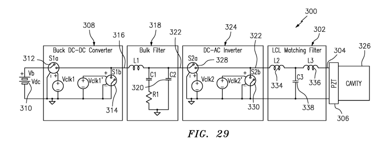
[0064] FIG. 29 is a circuit diagram of an RF power supply with an LCL network
that provides
a transducer drive signal to an ultrasonic transducer.
[0065] FIG. 30 is a graph illustrating a frequency response for an LC network.
[0066] FIG. 31 is a circuit diagram of a buck low pass filter used with the RF
power supply of
FIG. 29.
[0067] FIG. 32 is a block diagram illustration of a system for providing the
transducer drive
signal to the transducer.
[0068] FIG. 33 is a graph illustrating a frequency response for an acoustic
transducer.
[0069] FIG. 34 is a block diagram illustration of an alternative embodiment
system for
providing the transducer drive signal to the transducer.
[0070] FIG. 35 is a block diagram illustrating a calculation technique for
obtaining control
parameters for an acoustic transducer.
[0071] FIG. 36 is a block diagram illustrating demodulation of a voltage or
current signal.
[0072] FIG. 37 is a simplified illustration of an RF power supply including an
LC filter that
provides the transducer drive signal.
[0073] FIG. 38 is a simplified illustration of an alternative RF power supply
including an LCL
filter that provides the transducer drive signal.
[0074] FIG. 39 is a circuit diagram of an RF power supply that provides a
drive signal to an
LCL filter that provides a transducer drive signal to an ultrasonic
transducer.
- 9 -
,
CA 03022040 2018-10-24
WO 2017/189435
PCT/US2017/029145
[0075] FIG. 40 is a circuit illustration of an LCL filter circuit with a tap
that provides a current
sense signal and a node that provides a voltage sense signal that can be fed
back to a controller
(e.g., a DSP) to control the drive signal delivered to the transducer.
[0076] FIG. 41 is a schematic illustration of an embodiment of a power supply
with an LCL
filter network that provides a transducer drive signal.
DETAILED DESCRIPTION
[0077] The present disclosure may be understood more readily by reference to
the following
detailed description of desired embodiments and the examples included therein.
In the
following specification and the claims which follow, reference will be made to
a number of
terms which shall be defined to have the following meanings.
[0078] The singular forms "a," "an," and "the" include plural referents unless
the context
clearly dictates otherwise.
[0079] The term "comprising" is used herein as requiring the presence of the
named
components/steps and allowing the presence of other components/steps. The term
"comprising" should be construed to include the term "consisting of', which
allows the
presence of only the named components/steps, along with any impurities that
might result from
the manufacture of the named components/steps.
[0080] Numerical values should be understood to include numerical values which
are the same
when reduced to the same number of significant figures and numerical values
which differ from
the stated value by less than the experimental error of conventional
measurement technique of
the type described in the present application to determine the value.
[0081] All ranges disclosed herein are inclusive of the recited endpoint and
independently
combinable (for example, the range of "from 2 grams to 10 grams" is inclusive
of the endpoints,
2 grams and 10 grams, and all the intermediate values).
[0082] The terms "substantially" and "about" can be used to include any
numerical value that
can vary without changing the basic function of that value. When used with a
range,
"substantially" and "about" also disclose the range defined by the absolute
values of the two
- 10 -
CA 03022040 2018-10-24
WO 2017/189435
PCT/US2017/029145
endpoints, e.g. "about 2 to about 4" also discloses the range "from 2 to 4."
The terms
"substantially" and "about" may refer to plus or minus 10% of the indicated
number.
[0083] It should be noted that many of the terms used herein are relative
terms. For example,
the terms "upper" and "lower" are relative to each other in location, i.e. an
upper component is
located at a higher elevation than a lower component in a given orientation,
but these terms can
change if the device is flipped. The terms "inlet" and "outlet" are relative
to a fluid flowing
through them with respect to a given structure, e.g. a fluid flows through the
inlet into the
structure and flows through the outlet out of the structure. The terms
"upstream" and
"downstream" are relative to the direction in which a fluid flows through
various components,
i.e. the flow fluids through an upstream component prior to flowing through
the downstream
component. It should be noted that in a loop, a first component can be
described as being both
upstream of and downstream of a second component.
[0084] The terms "horizontal" and "vertical" are used to indicate direction
relative to an
absolute reference, i.e. ground level. The terms "above" and "below", or
"upwards" and
"downwards" are also relative to an absolute reference; an upwards flow is
always against the
gravity of the earth.
[0085] The present application refers to "the same order of magnitude." Two
numbers are of
the same order of magnitude if the quotient of the larger number divided by
the smaller number
is a value less than 10.
[0086] The acoustophoretic separation technology of the present disclosure
employs ultrasonic
acoustic standing waves to trap, i.e., hold stationary, particles or a
secondary fluid in a host
fluid stream. The particles or secondary fluid collect at the nodes or anti-
nodes of the multi-
dimensional acoustic standing wave, depending on the particles' or secondary
fluid's acoustic
contrast factor relative to the host fluid, forming clusters that eventually
fall out of the multi-
dimensional acoustic standing wave when the clusters have grown to a size
large enough to
overcome the holding force of the multi-dimensional acoustic standing wave
(e.g. by
coalescence or agglomeration). The scattering of the acoustic field off the
particles results in
a three-dimensional acoustic radiation force, which acts as a three-
dimensional trapping field.
The acoustic radiation force is proportional to the particle volume (e.g. the
cube of the radius)
when the particle is small relative to the wavelength. It is proportional to
frequency and the
acoustic contrast factor. It also scales with acoustic energy (e.g. the square
of the acoustic
- 11 -
CA 03022040 2018-10-24
WO 2017/189435
PCT/US2017/029145
pressure amplitude). For harmonic excitation, the sinusoidal spatial variation
of the force is
what drives the particles to the stable axial positions within the standing
waves. When the
acoustic radiation force exerted on the particles is stronger than the
combined effect of fluid
drag force and buoyancy and gravitational force, the particle is trapped
within the acoustic
standing wave field. This continuous trapping results in concentration,
aggregation, clustering,
agglomeration and/or coalescence of the trapped particles that will then
continuously fall out
of the multi-dimensional acoustic standing wave through gravity separation.
The strong lateral
forces create rapid clustering of particles. Relatively large solids of one
material can thus be
separated from smaller particles of a different material, the same material,
and/or the host fluid
through enhanced gravitational separation.
[0087] In this regard, the contrast factor is the difference between the
compressibility and
density of the particles and the fluid itself These properties are
characteristic of the particles
and the fluid themselves. Most cell types present a higher density and lower
compressibility
than the medium in which they are suspended, so that the acoustic contrast
factor between the
cells and the medium has a positive value. As a result, the axial acoustic
radiation force (ARF)
drives the cells, with a positive contrast factor, to the pressure nodal
planes, whereas cells or
other particles with a negative contrast factor are driven to the pressure
anti-nodal planes. The
radial or lateral component of the acoustic radiation force trap the cells.
The radial or lateral
component of the ARF is larger than the combined effect of fluid drag force
and gravitational
force. The radial or lateral component drives the cells/particles to planes
where they can cluster
into larger groups, which will then gravity separate from the fluid.
[0088] As the cells agglomerate at the nodes of the standing wave, there is
also a physical
scrubbing of the cell culture media that occurs whereby more cells are trapped
as they come in
contact with the cells that are already held within the standing wave. This
effect contributes to
separating the cells from the cell culture media. The expressed biomolecules
remain in the
nutrient fluid stream (i.e. cell culture medium).
[0089] For three-dimensional acoustic fields, Gor'kov's formulation can be
used to calculate
the acoustic radiation force Fac applicable to any sound field. The primary
acoustic radiation
force Fac is defined as a function of a field potential U,
FA¨V(U),
where the field potential U is defined as
- 12 -
CA 03022040 2018-10-24
WO 2017/189435
PCT/US2017/029145
3 p f (u2) -
U =V0 1(132) 2 fl _________________________ f2
C f 4
_
and fi and f2 are the monopole and dipole contributions defined by
1 2(A_1)
= =
A0-2 ' 2 2A+1'
where p is the acoustic pressure, u is the fluid particle velocity, A is the
ratio of cell density pp
to fluid density pf, a is the ratio of cell sound speed cp to fluid sound
speed cf, V. is the volume
of the cell, and <> indicates time averaging over the period of the wave.
Gor'kov's formulation
applies to particles smaller than the wavelength. For larger particle sizes,
Ilinskii provides
equations for calculating the 3D acoustic radiation forces for any particle
size. See Ilinskii,
Acoustic Radiation Force on a Sphere in Tissue, The Journal of the Acoustical
Society of
America, 132, 3, 1954 (2012), which is incorporated herein by reference.
[0090] An acoustic transducer can be driven to produce an acoustic wave. The
acoustic wave
can be reflected with another acoustic transducer or a reflector to generate
an acoustic standing
wave. Alternately, or in addition, two opposing acoustic transducers can be
driven to generate
an acoustic standing wave between them. Perturbation of the piezoelectric
crystal in an
ultrasonic transducer in a multimode fashion allows for generation of a
multidimensional
acoustic standing wave. A piezoelectric material or crystal can be
specifically designed to
deform in a multimode fashion at designed frequencies, allowing for generation
of a multi-
dimensional acoustic standing wave. The multi-dimensional acoustic standing
wave may be
generated by distinct modes of the piezoelectric material or crystal such as
the 3 x3 mode that
would generate multidimensional acoustic standing waves. A multitude of
multidimensional
acoustic standing waves may also be generated by allowing the piezoelectric
material or crystal
to vibrate through many different mode shapes. Thus, the crystal would excite
multiple modes
such as a Ox0 mode (i.e. a piston mode) to a 1 x 1, 2x2, 1x3, 3x1, 3x3, and
other higher order
modes and then cycle back through the lower modes of the crystal (not
necessarily in straight
order). This switching or dithering of the piezoelectric material or crystal
between modes
allows for various multidimensional wave shapes, along with a single piston
mode shape to be
generated over a designated time.
- 13 -
CA 03022040 2018-10-24
WO 2017/189435
PCT/US2017/029145
[0091] In some examples of the present disclosure, a single ultrasonic
transducer contains a
rectangular array of piezoelectric elements, which can be operated such that
some components
of the array will be out of phase with other components of the array. This
phased-array
arrangement can also separate materials in a fluid stream. A single
piezoelectric element may
be used rather than a piezoelectric array.
[0092] One specific application for the acoustophoresis device is in the
processing of
bioreactor materials. In a fed batch bioreactor, it is important at the end of
the production cycle
to filter all of the cells and cell debris from the expressed materials that
are in the fluid stream.
The expressed materials are composed of biomolecules such as recombinant
proteins or
monoclonal antibodies, and are the desired product to be recovered. Through
the use of
acoustophoresis, the separation of the cells and cell debris is very efficient
and leads to very
little loss of the expressed materials. The use of acoustophoresis is an
improvement over the
current filtration processes (depth filtration, tangential flow filtration,
centrifugation), which
show limited efficiencies at high cell densities, so that the loss of the
expressed materials in the
filter beds themselves can be up to 5% of the materials produced by the
bioreactor. The use of
mammalian cell culture includes Chinese hamster ovary (CHO), NSO hybridoma
cells, baby
hamster kidney (MK) cells, and human cells has proven to be a very efficacious
way of
producing/expressing the recombinant proteins and monoclonal antibodies used
to produce
pharmaceuticals. The filtration of the mammalian cells and the mammalian cell
debris through
acoustophoresis aids in greatly increasing the yield of the fed batch
bioreactor. The
acoustophoresis process, through the use of multidimensional acoustic waves,
may also be
coupled with a standard filtration process upstream or downstream, such as
depth filtration
using diatomaceous earth, tangential flow filtration (TFF), or other physical
filtration
processes.
[0093] Another type of bioreactor, a perfusion reactor, uses continuous
expression of the target
protein or monoclonal antibodies from the CHO cells. The continuous nature of
the perfusion
reactor enables a much smaller footprint in faster production cycle. The use
of acoustophoresis
to hold the CHO cells in a fluid stream as they are producing/expressing the
proteins is a very
efficient and closed loop way of production. It also allows for an increased
or maximum
production efficiency of the proteins and monoclonal antibodies in that none
of the materials
are lost in a filter bed.
- 14 -
CA 03022040 2018-10-24
WO 2017/189435
PCT/US2017/029145
[0094] In the fed batch bioreactor process, the acoustophoresis device uses
singular or multiple
standing waves to trap the cells and cell debris. The cells and cell debris,
having a positive
contrast factor, move to the nodes (as opposed to the anti-nodes) of the
standing wave. As the
cells and cell debris agglomerate at the nodes of the standing wave, there is
also a physical
scrubbing of the fluid stream that occurs whereby more cells are trapped as
they come in contact
with the cells that are already held within the standing wave. When the cells
in the multi-
dimensional acoustic standing wave agglomerate to the extent where the mass is
no longer able
to be held by the acoustic wave, the aggregated cells and cell debris that
have been trapped fall
out of the fluid stream through gravity, and can be collected separately. This
effect permits
cells to be separated in a continuous process of gravitational separation.
[0095] Advanced multi-physics and multiple length scale computer models and
high frequency
(MHz), high-power, and high-efficiency ultrasonic drivers with embedded
controls have been
combined to arrive at new designs of acoustic resonators driven by an array of
piezoelectric
transducers, resulting in acoustophoretic separation devices that far surpass
current capabilities.
[0096] Desirably, such transducers generate a multi-dimensional acoustic
standing wave in the
fluid that exerts a lateral force on the suspended particles/secondary fluid
to accompany the
axial force so as to increase the particle trapping capabilities of an
acoustophoretic system.
Typical results published in literature state that the lateral force is two
orders of magnitude
smaller than the axial force. In contrast, the technology disclosed in this
application provides
for a lateral force to be of the same order of magnitude as the axial force.
[0097] The system may be driven by a controller and amplifier (not shown). The
system
performance may be monitored and controlled by the controller. The parameters
of the
excitation of the transducer may be modulated. For example, the frequency,
current or voltage
of the transducer excitation or drive signal may be modulated to change
characteristics of the
generated acoustic standing wave. The amplitude modulation and/or by frequency
modulation
can be controlled by the computer. The duty cycle of the propagation of the
standing wave
may also be utilized to achieve certain results for trapping of materials. The
acoustic standing
wave may be turned on and/or shut off at different frequencies to achieve
desired results.
[0098] The lateral force of the total acoustic radiation force (MU) generated
by the ultrasonic
transducers of the present disclosure is significant and is sufficient to
overcome the fluid drag
force at high linear velocities up to 2 cm/s and beyond. For example, linear
velocities through
- 15 -
CA 03022040 2018-10-24
WO 2017/189435
PCT/US2017/029145
the devices of the present disclosure can be as small or smaller than 4 cm/min
for separation of
cells/particles, and can be as high as 2 cm/sec for separation of oil/water
phases. Flow rates
can be as small or smaller than 25 mL/min, and can range as high as 40 mL/min
to 1000
mL/min, or even higher. These flow rates in an acoustophoretic system are
applicable for batch
reactors, fed-batch bioreactors and perfusion bioreactors.
[0099] A diagrammatic representation of an embodiment for removing oil or
other lighter-
than-water material is shown in FIG. 1A. Excitation frequencies typically in
the range from
hundreds of kHz to lOs of MHz are applied by transducer 10. One or more
standing waves are
created between the transducer 10 and the reflector 11. Microdroplets or
particles 12 are
trapped in standing waves at the pressure anti-nodes 14 where they
agglomerate, aggregate,
clump, or coalesce, and, in the case of buoyant material, float to the surface
and are discharged
via an effluent outlet 16 located above the flow path. Clarified fluid is
discharged at outlet 18.
The acoustophoretic separation technology can accomplish multi-component
particle
separation without any fouling at a much-reduced cost.
[00100] A diagrammatic representation of an embodiment for removing
contaminants
or other heavier-than-water material is shown in FIG. 1B. Excitation
frequencies typically in
the range from hundreds of kHz to lOs of MHz are applied by transducer 10.
Contaminants in
the incoming fluid 13 are trapped in standing waves at the pressure nodes 15
where they
agglomerate, aggregate, clump, or coalesce, and, in the case of heavier
material, sink to the
bottom collector and are discharged via an effluent outlet 17 located below
the flow path.
Clarified water is discharged at outlet 18.
[00101] Generally, the transducers are arranged so that they cover the
entire cross-
section of the flow path. The acoustophoretic separation system of FIG. lA or
FIG. 1B has, in
certain embodiments, a square cross section of 6.375 inchesx6.375 inches which
operates at
flow rates of up to 5 gallons per minute (GPM), or a linear velocity of 12.5
mm/sec. The
transducers 10 are PZT-8 (Lead Zirconate Titanate) transducers with a 1 inchx
1 inch square
cross section and a nominal 2 or 3 MHz resonance frequency. Each transducer
consumes about
60 W of power for droplet trapping at a flow rate of 5 GPM. This power
consumption translates
in an energy cost of 0.500 kW hr/m3. This low power usage is an indication of
the very low
cost of energy of this technology. Desirably, each transducer is powered and
controlled by its
own amplifier. One application for this embodiment is to shift the particle
size distribution
- 16 -
CA 03022040 2018-10-24
WO 2017/189435
PCT/US2017/029145
through agglomeration, aggregation, clumping or coalescing of the micron-sized
oil droplets
into much larger droplets.
[00102] FIG. 2 is a cross-sectional diagram of a conventional ultrasonic
transducer. This
transducer has a wear plate 50 at a bottom end, epoxy layer 52, ceramic
crystal 54 (made of,
e.g. PZT), an epoxy layer 56, and a backing layer 58. On either side of the
ceramic crystal,
there is an electrode: a positive electrode 61 and a negative electrode 63.
The epoxy layer 56
attaches backing layer 58 to the crystal 54. The entire assembly is contained
in a housing 60
which may be made out of, for example, aluminum. An electrical adapter 62
provides
connection for wires to pass through the housing and connect to leads (not
shown) which attach
to the crystal 54. Typically, backing layers are designed to add damping and
to create a
broadband transducer with uniform displacement across a wide range of
frequency and are
designed to suppress excitation at particular vibrational eigenmodes. Wear
plates are usually
designed as impedance transformers to better match the characteristic
impedance of the
medium into which the transducer radiates.
[00103] FIG. 3A is a cross-sectional view of an ultrasonic transducer 81 of
the present "
disclosure, which can be used in acoustophoretic separator. Transducer 81 is
shaped as a disc
or a plate, and has an aluminum housing 82. The piezoelectric crystal is a
mass of perovskite
ceramic crystals, each consisting of a small, tetravalent metal ion, usually
titanium or
zirconium, in a lattice of larger, divalent metal ions, usually lead or
barium, and 02- ions. As
an example, a PZT (lead zirconate titanate) crystal 86 defines the bottom end
of the transducer,
and is exposed from the exterior of the housing. The crystal is supported on
its perimeter by a
small elastic layer 98, e.g. silicone or similar material, located between the
crystal and the
housing. Put another way, no wear layer is present.
[00104] Screws 88 attach an aluminum top plate 82a of the housing to the
body 82b of
the housing via threads. The top plate includes a connector 84 for powering
the transducer.
The top surface of the PZT crystal 86 is connected to a positive electrode 90
and a negative
electrode 92, which are separated by an insulating material 94. The electrodes
can be made
from any conductive material, such as silver or nickel. Electrical power is
provided to the PZT
crystal 86 through the electrodes on the crystal. Note that the crystal 86 has
no backing layer
or epoxy layer as is present in FIG. 2. Put another way, there is an air gap
87 in the transducer
between aluminum top plate 82a and the crystal 86 (i.e. the air gap is
completely empty). A
- 17 -
CA 03022040 2018-10-24
WO 2017/189435
PCT/US2017/029145
relatively minimal backing 58 and/or wear plate 50 may be provided in some
embodiments, as
seen in FIG. 3B.
[00105] The transducer design can affect performance of the system. A
typical
transducer is a layered structure with the ceramic crystal bonded to a backing
layer and a wear
plate. Because the transducer is loaded with the high mechanical impedance
presented by the
fluid, the traditional design guidelines for wear plates, e.g., half
wavelength thickness for
standing wave applications or quarter wavelength thickness for radiation
applications, and
manufacturing methods may not be appropriate. Rather, in one embodiment of the
present
disclosure the transducers have no wear plate or backing, allowing the crystal
(e.g., a
polycrystal, piezoelectric material or a single crystal (i.e., quartz)) to
vibrate in one of its
eigenmodes with a high Q-factor. The vibrating ceramic crystal/disk is
directly exposed to the
fluid flowing through the flow chamber.
[00106] Removing the backing (e.g. making the crystal air backed) also
permits the
ceramic crystal to vibrate at higher order modes of vibration with little
damping (e.g. higher
order modal displacement). In a transducer having a crystal with a backing,
the crystal vibrates
with a more uniform displacement, like a piston. Removing the backing allows
the crystal to
vibrate in a non-uniform displacement mode. The higher order the mode shape of
the crystal,
the more nodal lines the crystal has. The higher order modal displacement of
the crystal creates
more trapping lines, although the correlation of trapping line to node is not
necessarily one to
one, and driving the crystal at a higher frequency will not necessarily
produce more trapping
lines. See the discussion below with respect to FIGS. 8-9D.
[00107] In some embodiments, the crystal may have a backing that may
minimally
affects the Q-factor of the crystal (e.g. less than 5%). The backing may be
made of a
substantially acoustically transparent material such as balsa wood, foam, or
cork which allows
the crystal to vibrate in a higher order mode shape and maintains a high Q-
factor while still
providing some mechanical support for the crystal. The backing layer may be a
solid, or may
be a lattice having holes through the layer, such that the lattice follows the
nodes of the
vibrating crystal in a particular higher order vibration mode, providing
support at node
locations while allowing the rest of the crystal to vibrate freely. The goal
of the lattice work
or acoustically transparent material is to provide support without lowering
the Q-factor of the
crystal or interfering with the excitation of a particular mode shape.
- 18 -
CA 03022040 2018-10-24
WO 2017/189435
PCT/US2017/029145
[00108] Placing the crystal in direct contact with the fluid also
contributes to the high
Q-factor by avoiding the dampening and energy absorption effects of the epoxy
layer and the
wear plate. Other embodiments may have wear plates or a wear surface to
prevent the PZT,
which contains lead, contacting the host fluid. The insertion of a layer over
the PZT may be
desirable in, for example, biological applications such as separating blood.
Such applications
might use a wear layer such as chrome, electrolytic nickel, or electroless
nickel. Chemical
vapor deposition could also be used to apply a layer of poly(p-xylylene) (e.g.
Parylene) or other
polymer. Organic and biocompatible coatings such as silicone or polyurethane
are also usable
as a wear surface. A glassy carbon wear layer may also be utilized. Glassy
carbon, also known
as vitreous carbon, is a non-graphitizing carbon which combines both glassy
and ceramic
properties with those of graphite. The most important properties are high
temperature
resistance, hardness (7 Mohs), low density, low electrical resistance, low
friction and low
thennal resistance. Glassy carbon also has extreme resistance to chemical
attack and
impermeability to gases and liquids.
[00109] In the present disclosure, the piezoelectric crystal used in each
ultrasonic
transducer is modified to be in the form of a segmented array of piezoelectric
elements. This
array is used to form a multidimensional acoustic standing wave or waves,
which can be used
for acoustophoresis.
[00110] FIG. 4 shows a monolithic, one-piece, single electrode
piezoelectric crystal 200
that is used in ultrasonic transducers. The piezoelectric crystal has a
substantially square shape,
with a length 203 and a width 205 that are substantially equal to each other
(e.g. about one
inch). The crystal 200 has an inner surface 202, and the crystal also has an
outer surface 204
on an opposite side of the crystal which is usually exposed to fluid flowing
through the
acoustophoretic device. The outer surface and the inner surface are relatively
large in area, and
the crystal is relatively thin (e.g. about 0.040 inches for a 2 MHz crystal).
[00111] FIG. 5 shows a piezoelectric crystal 200' of the present
disclosure. The inner
surface 202 of this piezoelectric crystal 200' is divided into a piezoelectric
array 206 with a
plurality of (i.e. at least two) piezoelectric elements 208. However, the
array is still a single
crystal. The piezoelectric elements 208 are separated from each other by one
or more channels
or kerfs 210 in the inner surface 202. The width of the channel (i.e. between
piezoelectric
elements) may be on the order of from about 0.001 inches to about 0.02 inches.
The depth of
the channel can be from about 0.001 inches to about 0.02 inches. In some
instances, a potting
- 19 -
CA 03022040 2018-10-24
WO 2017/189435
PCT/US2017/029145
material 212 (i.e., epoxy, Sil-Gel, and the like) can be inserted into the
channels 210 between
the piezoelectric elements. The potting material 212 is non-conducting, acts
as an insulator
between adjacent piezoelectric elements 208, and also acts to hold the
separate piezoelectric
elements 208 together. Here, the array 206 contains sixteen piezoelectric
elements 208
(although any number of piezoelectric elements is possible), arranged in a
rectangular 4x4
configuration (square is a subset of rectangular). Each of the piezoelectric
elements 208 has
substantially the same dimensions as each other. The overall array 200' has
the same length
203 and width 205 as the single crystal illustrated in FIG. 4.
[00112] FIG. 6 shows another embodiment of a transducer 200". The
transducer 200"
is substantially similar to the transducer 200' of FIG. 5, except that the
array 206 is formed
from twenty-five piezoelectric elements 208 in a 5x5 configuration. Again, the
overall array
200" has the same length 203 and width 205 as the single crystal illustrated
in FIG. 4.
[00113] Each piezoelectric element in the piezoelectric array of the
present disclosure
may have individual electrical attachments (i.e. electrodes), so that each
piezoelectric element
can be individually controlled for frequency and power. These elements can
share a common
ground electrode. This configuration allows for not only the generation of a
multi-dimensional
acoustic standing wave, but also improved control of the acoustic standing
wave.
[00114] The piezoelectric array can be formed from a monolithic
piezoelectric crystal
by making cuts across one surface so as to divide the surface of the
piezoelectric crystal into
separate elements. The cutting of the surface may be performed through the use
of a saw, an
end mill, or other means to remove material from the surface and leave
discrete elements of the
piezoelectric crystal between the channels/grooves that are thus formed.
[00115] As explained above, a potting material may be incorporated into the
channels/grooves between the elements to form a composite material. For
example, the potting
material can be a polymer, such as epoxy. In particular embodiments, the
piezoelectric
elements 208 are individually physically isolated from each other. This
structure can be
obtained by filling the channels 210 with the potting material, then cutting,
sanding or grinding
the outer surface 204 down to the channels. As a result, the piezoelectric
elements are joined
to each other through the potting material, and each element is an individual
component of the
array. Put another way, each piezoelectric element is physically separated
from surrounding
piezoelectric elements by the potting material. FIG. 21 is a cross-sectional
view comparing
- 20 -
CA 03022040 2018-10-24
WO 2017/189435
PCT/US2017/029145
these two embodiments. On top, a crystal as illustrated in FIG. 5 is shown.
The crystal is
kerfed into four separate piezoelectric elements 208 on the inner surface 202,
but the four
elements share a common outer surface 204. On the bottom, the four
piezoelectric elements
208 are physically isolated from each other by potting material 212. No common
surface is
shared between the four elements.
[00116] In the present systems, the system is operated at a voltage such
that the particles
are trapped in the ultrasonic standing wave, i.e., remain in a stationary
position. The particles
are collected in along well defined trapping lines, separated by half a
wavelength. Within each
nodal plane, the particles are trapped in the minima of the acoustic radiation
potential. The
axial component of the acoustic radiation force drives the particles, with a
positive contrast
factor, to the pressure nodal planes, whereas particles with a negative
contrast factor are driven
to the pressure anti-nodal planes. The radial or lateral component of the
acoustic radiation
force is the force that traps the particle. In systems using typical
transducers, the radial or
lateral component of the acoustic radiation force is typically several orders
of magnitude
smaller than the axial component of the acoustic radiation force. However, the
lateral force in
the devices of the present disclosure can be significant, on the same order of
magnitude as the
axial force component, and is sufficient to overcome the fluid drag force at
linear velocities of
up to 1 cm/s. As discussed above, the lateral force can be increased by
driving the transducer
in higher order mode shapes, as opposed to a form of vibration where the
crystal effectively
moves as a piston having a uniform displacement. The acoustic pressure is
proportional to the
driving voltage of the transducer. The electrical power is proportional to the
square of the
voltage.
[00117] During operation, the piezoelectric arrays of the present
disclosure can be driven
so that the piezoelectric elements are in phase with each other. In other
words, each
piezoelectric element creates a multi-dimensional acoustic standing wave that
has the same
frequency and no time shift. In other embodiments, the piezoelectric elements
can be out of
phase with each other, i.e. there is a different frequency or time shift, or
they have a different
phase angle. As described further below, in more specific embodiments the
elements in the
array are arranged in groups or sets that are out of phase by multiples of 90
(i.e. 90 and/or
180 ).
= [00118] In embodiments, the pulsed voltage signal driving the
transducer can have a
sinusoidal, square, sawtooth, or triangle waveform; and have a frequency of
500 kHz to 10
- 21 -
CA 03022040 2018-10-24
WO 2017/189435
PCT/US2017/029145
MHz. The pulsed voltage signal can be driven with pulse width modulation,
which produces
any desired waveform. The pulsed voltage signal can also have amplitude or
frequency
modulation start/stop capability to eliminate streaming.
[00119] FIG. 7 is a lin-log graph (linear y-axis, logarithmic x-axis) that
shows the
calculated scaling of the acoustic radiation force, fluid drag force, and
buoyancy force with
particle radius. The buoyancy force is applicable to negative contrast factor
particles, such as
oil particles in this example. The calculated buoyancy force may include
elements of gravity
forces. In examples using positive contrast factor particles, which may be
some types of cells,
a line indicating gravity forces is used in a graph for such positive contrast
factor particles
showing acoustic radiation force and fluid drag force. In the present example
illustrated in
FIG. 7 calculations are done for a typical SAE-30 oil droplet used in
experiments. The
buoyancy force is a particle volume dependent force, e.g., proportional to the
radius cubed, and
is relatively negligible for particle sizes on the order of a micron, but
grows, and becomes
significant for particle sizes on the order of hundreds of microns. The fluid
drag force scales
linearly with fluid velocity, e.g., proportional to the radius squared, and
typically exceeds the
buoyancy force for micron sized particles, but is less influential for larger
sized particles on the
order of hundreds of microns. The acoustic radiation force scaling acts
differently than the
fluid drag force or the buoyancy force. When the particle size is small, the
acoustic trapping
force scales with the cube of the particle radius (volume) of the particle at
a close to linear rate.
Eventually, as the particle size grows, the acoustic radiation force no longer
increases linearly
with the cube of the particle radius. As the particle size continues to
increase, the acoustic
radiation force rapidly diminishes and, at a certain critical particle size,
is a local minimum.
For further increases of particle size, the radiation force increases again in
magnitude but with
opposite phase (not shown in the graph). This pattern repeats for increasing
particle sizes. The
particle size to acoustic radiation force relationship is at least partially
dependent on the
wavelength or frequency of the acoustic standing wave. For example, as a
particle increases
to a half-wavelength size, the acoustic radiation force on the particle
decreases. As a particle
size increases to greater than a half-wavelength and less than a full
wavelength, the acoustic
radiation force on the particle increases.
[00120] Initially, when a suspension is flowing through the acoustic
standing wave with
primarily small micron sized particles, the acoustic radiation force balances
the combined
effect of fluid drag force and buoyancy force to trap a particle in the
standing wave. In FIG. 7,
- 22 -
CA 03022040 2018-10-24
WO 2017/189435
PCT/US2017/029145
trapping occurs for a particle size of about 3.5 micron, labeled as Rd. In
accordance with the
graph in FIG. 7, as the particle size continues to increase beyond Rci, larger
particles are
trapped, as the acoustic radiation force increases compared to the fluid drag
force. As small
particles are trapped in the standing wave, particle coalescence / clumping /
aggregation /
agglomeration takes place, resulting in continuous growth of effective
particle size. Other,
smaller particles continue to be driven to trapping sites in the standing wave
as the larger
particles are held and grow in size, contributing to continuous trapping. As
the particle size
grows, the acoustic radiation force on the particle increases, until a first
region of particle size
is reached. As the particle size increases beyond the first region, the
acoustic radiation force
on the particle begins to decrease. As particle size growth continues, the
acoustic radiation
force decreases rapidly, until the buoyancy force becomes dominant, which is
indicated by a
second critical particle size, Ra, at which size the particles rise or sink,
depending on their
relative density or acoustic contrast factor with respect to the host fluid.
As the particles rise
or sink and leave the antinode (in the case of negative contrast factor) or
node (in the case of
positive contrast factor) of the acoustic standing wave, the acoustic
radiation force on the
particles may diminish to a negligible amount. The acoustic radiation force
continues to trap
small and large particles, and drive the trapped particles to a trapping site,
which is located at
a pressure antinode in this example. The smaller particle sizes experience a
reduced acoustic
radiation force, which, for example, decreases to that indicated near point
Ra. As other
particles are trapped and coalesce, clump, aggregate, agglomerate and/or
cluster together at the
node or antinode of the acoustic standing wave, effectively increasing the
particle size, the
acoustic radiation force increases and the cycle repeats. All of the particles
may not drop out
of the acoustic standing wave, and those remaining particles may continue to
grow in size.
Thus, FIG.7 explains how small particles can be trapped continuously in a
standing wave, grow
into larger particles or clumps, and then eventually rise or settle out
because of the relationship
between buoyancy force, drag force and acoustic radiation force with respect
to particle size.
[00121] The size, shape, and thickness of the transducer determine the
transducer
displacement at different frequencies of excitation, which in turn affects oil
separation
efficiency. Typically, the transducer is operated at frequencies near the
thickness resonance
frequency (half wavelength). Gradients in transducer displacement typically
result in more
places for oil to be trapped. Higher order modal displacements generate three-
dimensional
acoustic standing waves with strong gradients in the acoustic field in all
directions, thereby
creating equally strong acoustic radiation forces in all directions, leading
to multiple trapping
- 23 -
CA 03022040 2018-10-24
WO 2017/189435
PCT/US2017/029145
lines, where the number of trapping lines correlate with the particular mode
shape of the
transducer.
[00122] FIG. 8 shows the measured electrical impedance amplitude of a 1"
square PZT-
8 2-MHz transducer as a function of frequency in the vicinity of the 2.2 MHz
transducer
resonance. The minima in the transducer electrical impedance correspond to
acoustic
resonances of the water column and represent potential frequencies for
operation. Numerical
modeling has indicated that the transducer displacement profile varies
significantly at these
acoustic resonance frequencies, and thereby directly affects the acoustic
standing wave and
resulting trapping force. Since the transducer operates near its thickness
resonance, the
displacements of the electrode surfaces are essentially out of phase. The
typical displacement
of the transducer electrodes is not uniform and varies depending on frequency
of excitation.
As an example, at one frequency of excitation with a single line of trapped
oil droplets, the
displacement has a single maximum in the middle of the electrode and minima
near the
transducer edges. At another excitation frequency, the transducer profile has
multiple maxima
leading to multiple trapped lines of oil droplets. Higher order transducer
displacement patterns
result in higher trapping forces and multiple stable trapping lines for the
captured oil droplets.
[00123] To investigate the effect of the transducer displacement profile on
acoustic
trapping force and oil separation efficiencies, an experiment was repeated ten
times, with all
conditions identical except for the excitation frequency. Ten consecutive
acoustic resonance
frequencies, indicated by circled numbers 1-9 and letter A on FIG. 8, were
used as excitation
frequencies. These oscillations in the impedance correspond to the resonance
of the
acoustophoretic system. With the length of the acoustophoretic system being
2", the
oscillations are spaced about 15 kHz apart. The conditions were experiment
duration of 30
min, a 1000 ppm oil concentration of approximately 5-micron SAE-30 oil
droplets, a flow rate
of 500 ml/min, and an applied power of 20 W in a 1-inch widex2-inch long cross-
section.
[00124] As the emulsion passed by the transducer, the trapping lines of oil
droplets were
observed and characterized. The characterization involved the observation and
pattern of the
number of trapping lines across the fluid channel, as shown in FIG. 9A, for
seven of the ten
resonance frequencies identified in FIG. 8.
[00125] FIG. 9B shows an isometric view of the system in which the trapping
line
locations are being determined. FIG. 9C is a view of the system as it appears
when looking
- 24 -
CA 03022040 2018-10-24
WO 2017/189435
PCT/US2017/029145
down the inlet, along arrow 114. FIG. 9D is a view of the system as it appears
when looking
directly at the transducer face, along arrow 116. The trapping lines shown in
FIGs. 9B-9D are
those produced at frequency 4 in FIG. 8 and FIG. 9A.
[00126] The effect of excitation frequency clearly determines the number of
trapping
lines, which vary from a single trapping line at the excitation frequency of
acoustic resonance
and 9, to nine trapping lines for acoustic resonance frequency 4. At other
excitation
frequencies four or five trapping lines are observed. Different displacement
profiles of the
transducer can produce different (more) trapping lines in the standing waves,
with more
gradients in displacement profile generally creating higher trapping forces
and more trapping
lines.
[00127] Table 1 summarizes the findings from an oil trapping experiment
using a system
similar to FIG. 10A. An important conclusion is that the oil separation
efficiency of the
acoustic separator is directly related to the mode shape of the transducer.
Higher order
displacement profiles generate larger acoustic trapping forces and more
trapping lines resulting
in better efficiencies. A second conclusion, useful for scaling studies, is
that the tests indicate
that capturing 5 micron oil droplets at 500 ml/min implies 10 Watts of power
per square-inch
of transducer area per 1" of acoustic beam span. The main dissipation is that
of thermo-viscous
absorption in the bulk volume of the acoustic standing wave. The cost of
energy associated
with this flow rate is 0.500 kWh per cubic meter.
Table 1: Trapping Pattern Capture Efficiency Study
Resonance Total Power # of
Flow rate Duration Capture Efficiency
Peak Input Trapping
(ml/min) (min) (%)
Location (Watts) Lines
4 20 9 500 30 91%
8 20 5 500 30 58%
A 20 4 500 30 58%
9 20 2 500 30 37%
- 25 -
CA 03022040 2018-10-24
WO 2017/189435
PCT/US2017/029145
[00128] A 4" by 2.5" flow cross sectional area intermediate scale apparatus
124 for
separating a host fluid from a buoyant fluid or particulate is shown in FIG.
10A. The acoustic
path length is 4". The apparatus is shown here in an orientation where the
flow direction is
downwards, which is used for separating less-dense particles from the host
fluid. However,
the apparatus may be essentially turned upside down to allow separation of
particles which are
heavier than the host fluid. Instead of a buoyant force in an upward
direction, the weight of
the agglomerated particles due to gravity pulls them downward. It should be
noted that this
embodiment is depicted as having an orientation in which fluid flows
vertically. However, it
is also contemplated that fluid flow may be in a horizontal direction, or at
an angle.
[00129] A particle-containing fluid enters the apparatus through inlets 126
into an
annular plenum 131. The annular plenum has an annular inner diameter and an
annular outer
diameter. It is noted that the term "annular" is used here to refer to the
area between two
shapes, and the plenum does not need to be circular. Two inlets are visible in
this illustration,
though it is contemplated that any number of inlets may be provided as
desired. In particular
embodiments, four inlets are used. The inlets are radially opposed and
oriented.
[00130] A contoured nozzle wall 129 reduces the outer diameter of the flow
path in a
manner that generates higher velocities near the wall region and reduces
turbulence, producing
near plug flow as the fluid velocity profile develops, i.e. the fluid is
accelerated downward in
the direction of the centerline with little to no circumferential motion
component and low flow
turbulence. This chamber flow profile is desirable for acoustic separation and
particle
collection. The fluid passes through connecting duct 127 and into a
flow/separation chamber
128. As seen in the zoomed-in contoured nozzle 129 in FIG. 10B, the nozzle
wall also adds a
radial motion component to the suspended particles, moving the particles
closer to the
centerline of the apparatus and generating more collisions with rising,
buoyant agglomerated
particles. This radial motion will allow for optimum scrubbing of the
particles from the fluid
in the connecting duct 127 prior to reaching the separation chamber. The
contoured nozzle
wall 129 directs the fluid in a manner that generates large scale vortices at
the entrance of the
collection duct 133 to also enhance particle collection. Generally, the flow
area of the device
124 is designed to be continually decreasing from the annular plenum 131 to
the separation
chamber 128 to assure low turbulence and eddy formation for better particle
separation,
agglomeration, and collection. The nozzle wall has a wide end and a narrow
end. The term
scrubbing is used to describe the process of particle/droplet agglomeration,
aggregation,
- 26-
CA 03022040 2018-10-24
WO 2017/189435
PCT/US2017/029145
clumping or coalescing, that occurs when a larger particle/droplet travels in
a direction opposite
to the fluid flow and collides with smaller particles, in effect scrubbing the
smaller particles
out of the suspension.
[00131] Returning to FIG. 10A, the flow/separation chamber 128 includes a
transducer
array 130 and reflector 132 on opposite sides of the chamber. In use, multi-
dimensional
standing waves 134 are created between the transducer array 130 and reflector
132. These
standing waves can be used to agglomerate particles, and this orientation is
used to agglomerate
particles that are buoyant (e.g. oil). Fluid, containing residual particles,
then exits through flow
outlet 135.
[00132] As the buoyant particles agglomerate, they eventually overcome the
combined
effect of the fluid flow drag forces and acoustic radiation force, and their
buoyant force 136 is
sufficient to cause the buoyant particles to rise upwards. In this regard, a
collection duct 133
is surrounded by the annular plenum 131. The larger particles will pass
through this duct and
into a collection chamber 140. This collection chamber can also be part of an
outlet duct. The
collection duct and the flow outlet are on opposite ends of the apparatus.
[00133] It should be noted that the buoyant particles formed in the
separation chamber
128 subsequently pass through the connecting duct 127 and the nozzle wall 129.
This
arrangement causes the incoming flow from the annular plenum to flow over the
rising
agglomerated particles due to the inward radial motion imparted by the nozzle
wall.
[00134] The transducer setup of the present disclosure creates a three-
dimensional
pressure field which includes standing waves perpendicular to the fluid flow.
The pressure
gradients are large enough to generate acoustophoretic forces in a lateral
direction, e.g.,
orthogonal to the standing wave direction (i.e., the acoustophoretic forces
are parallel to the
fluid flow direction) which are of the same order of magnitude as the
acoustophoretic forces in
the wave direction. These forces permit enhanced particle trapping, clumping
and collection
in the flow chamber and along well-defined trapping lines, as opposed to
merely trapping
particles in collection planes as in conventional devices. The particles have
significant time to
move to nodes or anti-nodes of the standing waves, generating regions where
the particles can
concentrate, agglomerate, and/or coalesce, and then buoyancy/gravity separate.
[00135] In some embodiments, the fluid flow has a Reynolds number of up to
1500, i.e.
laminar flow is occurring. For practical application in industry, the Reynolds
number is usually
- 27 -
CA 03022040 2018-10-24
WO 2017/189435
PCT/US2017/029145
from 10 to 1500 for the flow through the system. The particle movement
relative to the fluid
motion generates a Reynolds number much less than 1Ø The Reynolds number
represents the
ratio of inertial flow effects to viscous effects in a given flow field. For
Reynolds numbers
below 1.0, viscous forces are dominant in the flow field. This situation
results in significant
damping where shear forces are predominant throughout the flow. This flow
where viscous
forces are dominant is called Stokes flow. The flow of molasses is an example.
Wall
contouring and streamlining have very little importance under such conditions.
These
characteristics are associated with the flow of very viscous fluids or the
flow in very tiny
passages, like MEMS devices. Inlet contouring has little importance. The flow
of the particles
relative to the fluid in an acoustophoretic particle separator will be Stokes
flow because both
the particle diameters and the relative velocities between the particles and
fluid are very small.
On the other hand, the Reynolds number for the flow through the system will be
much greater
than 1.0 because the fluid velocity and inlet diameter are much larger.
[00136] For Reynolds numbers much greater than 1.0, viscous forces are
dominant
where the flow is in contact with the surface. This viscous region near the
surface is called a
boundary layer and was first recognized by Ludwig Prandtl. In duct flow, the
flow will be
laminar if the Reynolds number is significantly above 1.0 and below 2300 for
fully developed
flow in the duct. The wall shear stress at the wall will diffuse into the
stream with distance.
At the inlet of the duct, flow velocity starts off uniform. As the flow moves
down the duct, the
effect of wall viscous forces will diffuse inward towards the centerline to
generate a parabolic
velocity profile. This parabolic profile will have a peak value that is twice
the average velocity.
The length of duct for the parabolic profile to develop is a function of the
Reynolds number.
For a Reynolds number of 20, which is typical for CHO operation, the
development length will
be 1.2 duct diameters. Thus, fully developed flow happens very quickly. This
peak velocity in
the center can be detrimental to acoustic particle separation. Also, at
laminar flow Reynolds
numbers turbulence, can occur and flow surface contouring is very important in
controlling the
flow. For these reasons, the separator was designed with an annular inlet
plenum and collector
tube.
[00137] The large annular plenum is followed by an inlet wall nozzle that
accelerates
and directs the fluid inward toward the centerline as shown in FIG. 10B. The
wall contour will
have a large effect on the profile. The area convergence increases the flow
average velocity,
- 28 -
CA 03022040 2018-10-24
WO 2017/189435
PCT/US2017/029145
but it is the wall contour that determines the velocity profile. The nozzle
wall contour will be
a flow streamline, and is designed with a small radius of curvature in the
separator.
[00138] The transducer(s) is/are used to create a pressure field that
generates forces of
the same order of magnitude both orthogonal to the standing wave direction and
in the standing
wave direction. When the forces are roughly the same order of magnitude,
particles of size 0.1
microns to 300 microns will be moved more effectively towards regions of
agglomeration
("trapping lines"). Because of the equally large gradients in the orthogonal
acoustophoretic
force component, there are "hot spots" or particle collection regions that are
not located in the
regular locations in the standing wave direction between the transducer 130
and the reflector
132. Hot spots are located at the minima of acoustic radiation potential. Such
hot spots
represent particle collection locations.
[00139] One application of the acoustophoretic device is the separation of
a biological
therapeutic protein from the biologic cells that produce the protein. In this
regard, current
methods of separation use filtration or centrifugation, either of which can
damage cells,
releasing protein debris and enzymes into the purification process and
increasing the load on
downstream portions of the purification system. It is desirable to be able to
process volumes
having higher cell densities, because this permits collection of larger
amounts of the therapeutic
protein and better cost efficiencies.
[00140] FIG. 11A and FIG. 11B are exploded views showing the various parts
of
acoustophoretic separators. FIG. 11A has only one separation chamber, while
FIG. 11B has
two separation chambers.
[00141] Referring to FIG. 11A, fluid enters the separator 190 through a
four-port inlet
191. An annular plenum is also visible here. A transition piece 192 is
provided to create plug
flow through the separation chamber 193. This transition piece includes a
contoured nozzle
wall, like that described above in FIG. 10A, which has a curved shape. A
transducer 40 and a
reflector 194 are located on opposite walls of the separation chamber. Fluid
then exits the
separation chamber 193 and the separator through outlet 195. The separation
chamber has a
rectangular-shaped flow path geometry.
[00142] FIG. 11B has two separation chambers 193. A system coupler 196 is
placed
between the two chambers 193 to join them together.
- 29 -
CA 03022040 2018-10-24
WO 2017/189435
PCT/US2017/029145
[00143] Acoustophoretic separation has been tested on different lines of
Chinese
hamster ovary (CHO) cells. In one experiment, a solution with a starting cell
density of
8.09x10⁶ cells/mL, a turbidity of 1,232 NTU, and cell viability of roughly 75%
was separated
using a system as depicted in FIG. 11A. The transducers were 2 MHz crystals,
run at
approximately 2.23 MHz, drawing 24-28 Watts. A flow rate of 25 mL/min was
used. The
result of this experiment is shown in FIG. 12A.
[00144] In another experiment, a solution with a starting cell density of
8.09x10⁶
cells/mL, a turbidity of 1,232 NTU, and cell viability of roughly 75% was
separated. This CHO
cell line had a bi-modal particle size distribution (at size 12 gm and 20 gm).
The result is
shown in FIG. 12B.
[00145] FIG. 12A and FIG. 12B were produced by a Beckman Coulter Cell
Viability
Analyzer. Other tests revealed that frequencies of 1 MHz and 3 MHz were not as
efficient as
2 MHz at separating the cells from the fluid.
[00146] In other tests at a flow rate of 10 L/hr, 99% of cells were
captured with a
confirmed cell viability of more than 99%. Other tests at a flow rate of 50
mL/min (i.e. 3 L/hr)
obtained a final cell density of 3 x10⁶ cells/mL with a viability of nearly
100% and little to no
temperature rise. In yet other tests, a 95% reduction in turbidity was
obtained at a flow rate of
6 L/hr.
[00147] Testing on the scaled unit shown in FIG. 10A-10B was performed
using yeast
as a simulant for CHO for the biological applications. Fot these tests, at a
flow rate of 15 L/hr,
various frequencies were tested as well as power levels. Table 2 shows the
results of the testing.
Table 2: 2.5" x 4" System results at 15 L/hr Flow rate
Frequency (MHz) 30 Watts 37 Watts 45 Watts
2.2211 93.9 81.4 84.0
2.2283 85.5 78.7 85.4
2.2356 89.1 85.8 81.0
- 30 -
CA 03022040 2018-10-24
WO 2017/189435
PCT/US2017/029145
2.243 86.7 79.6
[00148] In biological applications, many parts, e.g. the tubing leading to
and from the
housing, inlets, exit plenum, and entrance plenum, may all be disposable, with
only the
transducer and reflector to be cleaned for reuse. Avoiding centrifuges and
filters allows better
separation of the CHO cells without lowering the viability of the cells. The
form factor of the
acoustophoretic separator is also smaller than a filtering system, allowing
the CHO separation
to be miniaturized. The transducers may also be driven to create rapid
pressure changes to
prevent or clear blockages due to agglomeration of CHO cells. The frequency of
the
transducers may also be varied to obtain optimal effectiveness for a given
power.
[00149] The following examples are provided to illustrate the apparatuses,
components,
and methods of the present disclosure. The examples are merely illustrative
and are not
intended to limit the disclosure to the materials, conditions, or process
parameters set forth
therein.
EXAMPLES
[00150] A two-dimensional numerical model was developed for the
acoustophoretic
device using COMSOL simulation software. The model is illustrated in FIG. 13.
The device
included an aluminum wall 222, and a stainless steel reflector 224 opposite
the wall. Embedded
in the wall was a piezoelectric transducer 230. As illustrated here, the
transducer is in the form
of a 4-element piezoelectric array. The wall 222 and the reflector 224 define
a flow chamber,
with arrow 225 indicating the flow direction of fluid through the chamber. The
piezoelectric
transducer was in direct contact with the fluid. Channels/kerfs 210 and
potting material 212
are also illustrated, though potting material was not used in the simulation.
[00151] The simulation software was run, and its output was compared to
published data
(Barmatz, J. Acoust. Soc. Am. 77, 928, 1985). FIG. 14A compares the acoustic
potential U.
FIG. 14B compares the x-component of the acoustic radiation force (ARF). FIG.
14C
compares the y-component of the ARF. FIG. 14D compares the absolute value of
the ARF. In
these figures, the published data is on the top, while the numerical model
results are on the
-31 -
CA 03022040 2018-10-24
WO 2017/189435
PCT/US2017/029145
_ _
bottom. As can be seen here, the results of the numerical model match the
published data,
which validates the numerical model and subsequent calculations made
therefrom.
[00152] Three different simulations were then run to model the separation
of SAE 30 oil
droplets from water using three different piezoelectric transducers: a 1-
element transducer (i.e.
single crystal), a 4-element transducer, and a 5-element transducer. The
transducers were
operated at the same frequency, and the following parameters were used for the
oil and the
water: oil particle radius (Rp)=10 ttm; oil density (pp)=865 kg/m3; speed of
sound in oil
(cp)=1750 m/sec; particle velocity (uf)=0.001 kg/m= sec; water density
(pf)=1000 kg/m3; and
speed of sound in water (cf)=1500 m/sec.
[00153] For the 4-element transducer, each channel had a width of 0.0156
inches and a
depth of 0.0100 inches, and each element had a width of 0.2383 inches (total
width of the
transducer was one inch). For the 5-element transducer, each channel had a
width of 0.0156
inches and a depth of 0.0100 inches, and each element had a width of 0.1875
inches.
[00154] FIG. 15 shows the simulation of the forces on a particle using the
1-element
transducer, which is a two-dimensional representation of PZT crystal 200. FIG.
16 shows the
simulation of the forces on a particle using the 4-element transducer, which
is a two-
dimensional representation of PZT crystal 200'. FIG. 17 shows the simulation
of the forces on
a particle using the 5-element transducer, which is a two-dimensional
representation of PZT
crystal 200". Each transducer had the same width, regardless of the number of
elements. The
amplitude of the multi-dimensional acoustic standing waves generated therefrom
are clearly
seen (lighter area is higher amplitude than darker area).
[00155] Next, simulations were run on a 4-element array to compare the
effect of the
phase on the waves. The flow rate was 500 mL/min, the Reynolds number of the
fluid was
220, the input voltage per element was 2.5 VDC, and the DC power per element
was 1 watt.
In one simulation, the four elements were in a 0-180-0-180 phase (i.e. out of
phase) with respect
to each other. In another simulation, the four elements were all in phase with
each other. The
simulations were then compared to actual experiments conducted with a
transducer device
having a 4x4 piezoelectric array as in FIG. 18.
[00156] FIG. 19 compares the results of the out-of-phase simulation (left)
with a picture
(right) showing the actual results when an out-of-phase array was used in the
transducer device
- 32 -
CA 03022040 2018-10-24
WO 2017/189435 PCT/US2017/029145
of FIG. 18. The results are very similar. Where the amplitude is high in the
simulation, trapped
particles are seen in the actual picture.
[00157] FIG. 20
compares the results of the in-phase simulation (left) with a picture
(right) showing the actual results when an in-phase array was used in the
transducer device of
FIG. 18. The results are very similar.
[00158]
Additional numerical models were performed with the 4-element transducer and
the 5-element transducer, either in-phase or out-of-phase in different
arrangements, as
described in Table 3 below, over a frequency sweep of 2.19 MHz to 2.25 MHz,
for oil droplets
of diameter 20 microns. Out-of-phase means that adjacent elements are excited
with different
phases.
[00159] FIG. 22
is a diagram illustrating the two out-of-phase modes that were simulated
for the 4-element array. The left-hand side illustrates the 0-180-0-180 mode,
while the right-
hand side illustrated the 0-180-180-0 mode. FIG. 23 is a diagram illustrating
the four out-of-
phase modes that were simulated for the 5-element array. The top left picture
illustrates the 0-
180-0-180-0 mode. The top right picture illustrates the 0-0-180-0-0 mode. The
bottom left
picture illustrates the 0-180-180-180-0 mode. The bottom right picture
illustrates the 0-90-
180-90-0 mode.
[00160] The
ratio of the lateral (x-axis) force component to the axial (y-axis) force
component of the acoustic radiation force was determined over this frequency
range, and the
range of that ratio is listed in Table 3 below.
Table 3.
Transducer Phase Ratio Min Ratio Max
1-Element (single crystal) ¨0.15
4-Element Array In-Phase ¨0.08 ¨0.54
4-Element Array (0-180-0-180) ¨0.39 ¨0.94
4-Element Array (0-180-180-0) ¨0.39 ¨0.92
- 33 -
CA 03022040 2018-10-24
WO 2017/189435 PCT/US2017/029145
5-Element Array In-Phase ¨0.31 ¨0.85
5-Element Array (0-180-0-180-0) ¨0.41 ¨0.87
5-Element Array (0-0-180-0-0) ¨0.41 ¨0.81
5-Element Array (0-180-180-180-0) ¨0.40 ¨0.85
5-Element Array (0-90-180-90-0) ¨0.38 ¨0.81
[00161] FIG. 24
shows the normalized acoustic radiation force (ARF) from the single
piezoelectric crystal simulation. The ARF value was normalized with the real
power calculated
with the measured voltage and current. FIG. 25 shows the ratio of the ARF
components (lateral
to axial) for the single piezoelectric crystal simulation over the tested
frequency range. FIG.
26 shows the normalized acoustic radiation force (ARF) from the 5-element
simulation. FIG.
27 shows the ratio of the ARF components (lateral to axial) for the 5-element
simulation over
the tested frequency range. Comparing FIG. 24 to FIG. 26, the peak ARF for the
1-element
simulation is about 6e-11, while the peak ARF for the 5-element simulation is
about 2e-9.
Comparing FIG. 25 to FIG. 27, the ratio of the forces is also more consistent,
with a variation
of about 0.60 compared to about 0.40.
[00162]
Generally, the 4-element and 5-element arrays produced high ratios, including
some greater than 0.9. Some of the simulations also had acoustic radiation
force amplitudes
that were almost two orders of magnitude higher than those produced by the 1-
element
transducer (which served as the baseline).
[00163]
Experimental 16-element arrays and 25-element arrays were then tested. The
feed solution was a 3% packed cell mass yeast solution, used as a simulant for
CHO cells for
biological applications. For out-of-phase testing, a checkerboard pattern of 0
and 180 phases
was used. For the 25-element array, 12 elements were at 180 and 13 elements
were at 0 .
These checkerboard patterns are illustrated in FIG. 28. The left-hand side is
the 16-element
array and the right-hand side is the 25-element array, with the different
shades indicating the
different phase angle.
- 34 -
CA 03022040 2018-10-24
WO 2017/189435 PCT/US2017/029145
[00164] The turbidity of the feed, concentrate, and permeate were measured
after 30
minutes at various frequencies. The concentrate was the portion exiting the
device that
contained the concentrated yeast, along with some fluid. The permeate was the
filtered portion
exiting the device, which was mostly liquid with a much lower concentration of
yeast. A lower
turbidity indicated a lower amount of yeast. The capture efficiency was
determined as (feed-
permeate)/feed*100%. The feed rate was 30 mL/min, and the concentrate flow
rate was 5
mL/min. The power to the transducers was set at 8 W.
[00165] Table 4 lists results for the single-element transducer, which is
used as a
baseline or control.
Table 4.
Frequency (MHz) 2.225 2.244
Concentrate (NTU) 15,400 15,400
Permeate (NTU) 262 327
Feed (NTU) 4,550 5,080
Capture Efficiency (%) 94.2 93.6
[00166] Table 5 lists results for the 16-element in-phase experiments.
Table 5.
Frequency (Wiz) 2.22 2.225 2.23 2.242 2.243 2.244 2.255 2.26
Concentrate (NTU) 22,700 24,300 22,500 24,600 23,100 28,100 27,400 23,800
Permeate (NTU) 205 233 241 201 249 197 244 165
Feed (NTU) 5,080 4,850
5,100 4,830 4,810 5,080 4,940 4,830
Capture Efficiency (%) 96.0 95.2 95.3 95.8 94.8 96.1 95.1
96.6
- 35 -
CA 03022040 2018-10-24
WO 2017/189435 PCT/US2017/029145
[00167] Table 6 lists results for the 16-element out-of-phase experiments.
Table 6.
Frequency (MHz) 2.22 2.225
2.23 2.242 2.243 2.244 2.255 2.26
Concentrate (NTU) 40,900 21,400 26,000 49,300 19,100 55,800 22,100 35,000
Permeate (NTU) 351 369 382 1,690 829 761 397 581
Feed (NTU) 5,590 4,870
5,860 5,160 5,040 4,870 4,800 5,170
Capture Efficiency (%) 93.7 92.4 93.5 67.2 83.6 84.4 91.7
88.8
[00168] Comparing the 16-element array results to each other and the
control, the in-
phase array maintains high capture efficiency through the frequency range,
while the out-of-
phase array drops off quickly around 2.24 MHz. The efficiency results are very
similar to the
control for most in-phase tests. The in-phase efficiency was higher than the
out-of-phase
efficiency at every frequency.
[00169] Table 7 lists results for the 25-element in-phase experiments.
Table 7.
Frequency (MHz) 2.2190 2.2300 2.2355 2.2470 2.2475 2.2480 2.2485 2.2615
Concentrate (NTU) 13,300 19,800 20,900 21,400 13,700 17,300 19,000 19,500
Permeate (NTU) 950 669 283 1,044 1,094 1,164 688 797
Feed (NTU) 4,930 4,930
4,910 5,010 4,950 5,220 5,010 5,110
Capture Efficiency (%) 80.7 86.4 94.2 79.2 77.9 77.7 86.3
84.4
[00170] Table 8 lists results for the 25-element out-of-phase experiments.
Table 8.
- 36 -
CA 03022040 2018-10-24
WO 2017/189435 PCT/US2017/029145
Frequency (MHz) 2.2190
2.2300 2.2355 2.2470 2.2475 2.2480 2.2485 2.2615
Concentrate (NTU) 14,605 - 21,700
18,025 23,425 22,575 21,900 22,450
Permeate (NTU) 2,568 2,541 1,484 1,134 1,005 987 905 2,034
Feed (NTU) 5,610 6,020
5,200 6,010 5,880 5,840 5,860 5,880
Capture Efficiency (%) 54.2 57.8 71.5 81.1 82.9 83.1 84.6
65.4
[00171] Comparing the 25-element array results to each other and the
control, both
arrays are less efficient than the control. The 25-element in-phase array
peaks around 95% and
then drops off in both directions. The out-of-phase array peaks around 85%
efficiency and
drops off sharply. The efficiency results are very similar to the control. It
should be noted that
the high peak amplitudes found using the numerical model have not been tested
experimentally.
[00172] FIG. 29 is a circuit diagram of an RF power supply 300 with an LCL
filter
network 302 that provides a transducer drive signal on a line 304 to an
ultrasonic transducer
306. In this embodiment, a DC-DC converter 308 receives a first DC voltage
from a source
310 and switches 312, 314 (e.g., power MOSFETs) are cooperatively switched
under the
control of a controller (not shown) to generate a pulse width modulated (PWM)
signal that is
provided on a line 316. The switches 312, 314 are driven by first
complementary clocking
signals generated by the controller, and have the same frequency and duty
cycle. The switches
may not be closed at the same time, and the switching action produces a
chopped voltage Vb
across the switch 314. The resultant PWM signal on the line 316 is received by
a filter 318
(e.g., a buck filter) that filters the signal on the line 318 so the average
voltage appears across
capacitor C2 320, and is provided on line 322 to a DC-AC inverter 324. The
bandwidth of the
filter 318 is selected so the voltage on the line 322 follows changes in the
duty cycle of the
clocking signals that drive the switches 312, 314 based upon dynamic changes
in acoustic
cavity 326. Second complementary clocking signals generated by the controller
drive switches
328, 330 to perform the DC to AC inversion, and a resultant AC signal is
provided on line 332.
The AC signal is then input to the matching filter network 302 (e.g., an LC,
LCL, et cetera)
which filters the input to attenuate higher frequency components of the input
and provide a
periodic signal such a sine wave on the line 304 to drive the transducer 306.
In this
- 37 -
CA 03022040 2018-10-24
WO 2017/189435
PCT/US2017/029145
embodiment, the LCL filter 302 includes serially connected inductors L2, L2,
334, 336,
respectively and a capacitor C3 338 that extends from a node between the
inductors 334, 336
to ground. LCL circuit 302 filters the output of the inverter 324 and matches
the transducer
306 to the inverter 324 for improved power transfer.
[00173] The matching filter 302 provides impedance scaling to obtain an
appropriate
load for the inverter drive. The matching filter can be considered a network,
which is tuned to
provide desired power transfer, such as optimized power transfer, through the
transducer 306
and into the resonant cavity 326. Considerations for implementing the filter
302 (e.g., LC or
LCL) include the combined response of the transducer 306 and the resonant
cavity 326.
According to one example, the filter permits desired power transfer, such as
optimized power
transfer, when the acoustic transducer is operated in a multi-dimensional
mode, or in a multi-
mode, for example, with multiple overlaid vibrational modes that produce one
or more primary
or dominant vibrational modes. A desired mode of operation is at a frequency
that corresponds
to a low or minimum reactance point of the response of the transducer, and/or
the response of
the transducer/resonant cavity combination.
[00174] For a fixed resonant frequency, the matching filter 302 may deliver
different
amounts of power based on the system resonance(s) in accordance with the
combination of
inductor and capacitor values that are used to font' the matching filter
network. FIG. 30
illustrates a response curve for matching filter configured as a LC network
with an inductor
value of 1.596 uH and a capacitor value of 3.0 nF. The resonant frequency of
the LC network
is 2.3 MHz. Referring to FIG. 30, the resistive impedance is labeled A, the
reactive impedance
is labeled B, the input real power is labelled C and the acoustic real power
into the cavity is
labelled D. With regard to the power delivered into the system, increasing the
capacitor value
with the same resonance increases power into the system. In general, changing
the values of
the inductor and/or capacitor can influence the resonant frequency of the LC
network.
Changing the resonant frequency of the LC network changes the frequency at
which optimum
power transfer occurs, and can impact the efficiency of the transfer. For
example, the frequency
for optimum power transfer relative to lower or minimum reactance points
(label B) of the
input impedance of the system is influenced by the resonance frequency of the
LC network.
[00175] The plot in FIG. 30 shows the points on the input real power (C)
and the acoustic
real power (D) at a reactance minimum. The input real power and acoustic real
power are fairly
well matched, indicating efficient transfer of power. If the value of the
inductor is changed to
- 38 -
CA 03022040 2018-10-24
WO 2017/189435
PCT/US2017/029145
0.8 uH and the value of the capacitor is changed to 6.0 nF, then the same
reactance minimum
produces a greater power transfer with somewhat less efficiency. The power
transfer becomes
less efficient when the input real power (C) is significantly different
(greater) than the acoustic
real power (D). In some instances, depending on the inductor and capacitor
values, power
transfer can be highly efficient, however, the frequency operating point may
not be at a
minimum reactance point (B). Accordingly, choices can be made between
operating the
transducer to obtain highly efficient separation in the acoustic chamber,
implying a minimum
reactance point, and obtaining efficient power transfer into the chamber. For
a given material
being separated and a given transducer, an LC network can be selected with a
resonance
=
frequency to obtain efficient power transfer into the acoustic cavity,
improving overall system
efficiency.
[00176] FIG. 31 is a circuit diagram of one embodiment of the buck
filter 318 illustrated
in FIG. 29. The component values illustrated in FIG. 31 are presented by way
of example,
other values and component combinations may be used to provide the desired
filtering.
[00177] FIG. 32 is a block diagram illustration of a system 350 for
providing a
transducer drive signal on the line 352 to an acoustic transducer 354.
Referring to FIG. 32, the
system 350 controls the transducer 354, which is coupled to an acoustic
chamber 356. The
acoustic transducer 354 is driven by an RF power converter composed of a DC
source 358
(e.g., 48 volts DC), a DC-DC converter 360 (e.g., a buck converter) and a RF
DC-AC inverter
362. Inverter output drive signal on line 364 is input to a low pass filter
365 (e.g., an LC or
LCL matching low pass filter as shown in FIG. 29) and the resultant filtered
signal on line 367
is sensed to obtain a voltage sense signal on line 366 and a current sense
signal on line 368,
which are fed back to controller 370. The controller 370 provides control
signals to the
converter 360 and the inverter 362 to control the drive signal on the line
364.
[00178] The signal provided by the controller 370 to the converter 360
is a pulse width
measure, which determines the duty cycle of the switching signals in the
converter 360. The
duty cycle determines the DC level on converter output signal on line 372,
which is applied to
the inverter 362. For example, the greater the duty cycle, the higher the DC
output on the line
372. The controller 370 provides control signals to the inverter 362 that
determine the
frequency of operation of the inverter. The control signals provided to the
inverter 362 may be
switching signals, for switching switches (e.g., FETs) in the inverter, an
example of such
switches being shown in FIG. 29. Alternately, or in addition, the controller
370 may provide
- 39 -
CA 03022040 2018-10-24
WO 2017/189435
PCT/US2017/029145
a control signal to the inverter 362 that is used to indicate a desired
switching frequency, and
circuitry internal to the inverter interprets the control signal and switches
the internal switches
in accordance with the interpreted control signal.
[00179] The voltage sense signal on the line 366 and the current sense
signal on the line
368 are provided to the controller 370 as feedback signals to control the
drive signal on the line
364 provided to the acoustic transducer 354. The controller 370 performs
operations and
calculations on the feedback signals on the lines 366, 368, for example, to
obtain a power
measure, P = V*I, or to obtain a phase angle, 0 = arctan (XJR).
[00180] The controller 370 is provisioned with a control scheme that
accepts process
settings, such as power output, range of frequency operation, or other user
selectable
parameters, and provides control signals to the converter 360 and the inverter
362 based on the
process settings and the feedback values. For example, as described above, the
controller can
sequence through a number of frequencies in a range of frequencies that are
provided to the
inverter 362 to scan through the frequency range and determine the
characteristics of the
transducer 354 or the transducer 354 in combination with the acoustic chamber
356, which may
be under load. The results of the frequency scan in terms of voltage and
current obtained from
the feedback signals on the lines 366, 368 are used to identify
characteristics of the impedance
curves for the components or the system, such as is illustrated in FIG. 33.
FIG. 33 is a graph
illustrating a frequency response for an acoustic transducer.
[00181] The frequency scan can be implemented to occur at set up, and/or at
intervals
during operation of the illustrated system. During steady-state operation, the
frequency scan
can be conducted to identify desired set points for operation, such as power
or frequency, based
on user settings and feedback values. The control scheme implemented by the
controller 370
is thus dynamic, and responds to changing conditions in the system, such as
may be
encountered with frequency drift, temperature change, load changes and any
other system
parameter changes. The dynamic nature of the control scheme permits the
controller to respond
to or compensate for nonlinearities, such as may be encountered as components
age or lose
tolerance. Accordingly, the control scheme is adaptive and can accommodate
system changes.
[00182] Referring still to FIG. 32, some examples of system operation
include driving
the acoustic transducer 354 to produce an acoustic standing wave (e.g., a
multidimensional
acoustic standing wave) in the acoustic chamber 356. For example, a 3D
acoustic wave may
- 40 -
CA 03022040 2018-10-24
WO 2017/189435
PCT/US2017/029145
be stimulated by driving the acoustic transducer 354, which may be implemented
as a
piezoelectric crystal, sometimes referred to herein as a PZT, near its anti-
resonance frequency.
Cavity resonances modulate the impedance profile of the PZT as well as affect
its resonance
modes. Under the influence of the 3D acoustic field, suspended particles in
the liquid medium
in the acoustic cavity 356 are forced into agglomerated sheets and then into
strings of 'beads'
of agglomerated material. Once particle concentrations reach a critical size,
gravitational
forces take over and the agglomerated material drops out of the acoustic field
and to the bottom
of the chamber. The changing concentrations of agglomerated material as well
as the dropping
out of that material affects the cavity's resonances which in turn change the
acoustic loading
on the PZT and its corresponding electrical impedance. The changing dynamics
of the
collected material detunes the cavity and PZT reducing the effects of the 3D
wave in clarifying
the medium. Additionally, changes in the medium and cavity temperature also
detune the
cavity so that clarification is reduced. To track the resonance changes
occurring in the cavity,
a control technique is used to follow changes in the PZT's electrical
characteristics.
[00183] A strong 3D acoustic field can be generated by driving the PZT at a
frequency
where its input impedance is a complex (real and imaginary) quantity. However,
cavity
dynamics can cause that impedance value to change significantly in an erratic
manner. The
changes in impedance are due, at least in part, to changes in the load applied
to the acoustic
transducer 354 and/or the acoustic chamber 356. As particles or secondary
fluid is separated
from a primary or host fluid, the loading on the acoustic transducer and/or
the acoustic chamber
changes, which in turn can influence the impedance of the acoustic transducer
and/or the
acoustic chamber.
[00184] To correct for detuning, the controller 370 calculates the PZT
impedance from
the feedback signals on the lines 366, 368 to change the operating frequency
to compensate for
the detuning. Since frequency changes affect power delivered to the chamber
356, the
controller 370 also determines how to adjust the output voltage of the
(dynamic) converter 360
to maintain the desired amount of power output from the RF DC-AC inverter 362
and into the
acoustic transducer 354 and/or the acoustic chamber 356.
[00185] The converter 360 (e.g., a buck converter) is an electronically
adjustable DC-
DC power supply and is the power source for the inverter 362. The inverter 362
converts the
DC voltage on the line 372 to a high-frequency AC signal on the line 364,
which is filtered by
filter 365 to create a transducer drive signal that drives the PZT 354. The
dynamics in the
- 41 -
CA 03022040 2018-10-24
WO 2017/189435
PCT/US2017/029145
chamber 356 occur at rates corresponding to frequencies in the low audio band.
Consequently,
the converter 360, the controller 370, and the DC-AC inverter 362 are capable
of working at
rates faster than the low audio band to permit the controller to track chamber
dynamics and
keep the system in tune.
[00186] The controller 370 can simultaneously change the frequency of the
DC-AC
inverter 362 and the DC voltage coming out of the buck converter 360 to track
cavity dynamics
in real time. The control bandwidth of the system is a function of the RF
bandwidth of the
inverter and the cutoff frequency of the filtering system of the buck
converter (e.g., see filter
318 in FIG. 29).
[00187] The controller 370 can be implemented as a DSP (digital signal
processor)
control, microcontroller, microcomputer, et cetera or as an application
specific integrated
circuit (ASIC) or a field programmable gate array (FPGA) control, as examples.
The controller
may be implemented with multiple channels, to permit parallel processing, for
example to
analyze real and/or reactive impedance, voltage, current and power.
[00188] The acoustic dynamics of the cavity 356 affects the electrical
characteristics of
the PZT 354, which affects the voltage and current drawn by the PZT. The
sensed PZT voltage
and current fed back on the lines 366, 368 is processed by the controller 370
to compute the
real-time power consumed by the PZT as well as its instantaneous impedance
(affected by
acoustic dynamics). Based on user set points the controller 370 adjusts, in
real-time, the DC
power supplied on the line 372 to the inverter 362, and the frequency at which
the inverter is
operated to track cavity dynamics and maintain user set points. The filter 365
(e.g., an LC or
LCL, et cetera) is used to impedance match the output impedance of the
inverter 362 to increase
power transfer efficiency.
[00189] The controller 370 samples the feedback signals on the lines 366,
368 fast
enough to detect changes in cavity performance (e.g., via changes in PZT
impedance) in real
time. For example, the controller 370 may sample the feedback signals on the
lines 366, 368
at one hundred million samples per second. Signal processing techniques are
implemented to
permit a wide dynamic range for system operation to accommodate wide
variations in cavity
dynamics and applications. The DC-DC converter 360 can be configured to have a
fast
response time to follow the signal commands coming from the controller 370.
The inverter
362 can drive a wide range of loads that demand varying amounts of real and
reactive power
- 42 -
CA 03022040 2018-10-24
WO 2017/189435
PCT/US2017/029145
that change over time. The electronics package used to implement the system
illustrated in
FIG. 32 may be configured to meet or exceed UL and CE specifications for
electromagnetic
interference (EMI).
[00190] FIG. 34 is a block diagram illustration of an alternative
embodiment system 380
for providing the transducer drive signal 352 to the transducer 354. The
embodiment of FIG.
34 is substantially the same as the embodiment in FIG. 32, with a primary
difference that the
DC-DC converter 360 and DC-AC inverter 362 of FIG. 32 have been replaced by a
linear
amplifier 382 (FIG. 32). In addition, the output of controller 384 would be an
analog sine wave
on line 386 that is input to the linear amplifier 382. Referring to FIG. 35,
the controller 384
may be implemented with very-high-speed parallel digital-signal-processing
loops using RTL
(Register Transfer Level) which is realized in actual digital electronic
circuits inside a field-
programmable-gate-array (FPGA). Two high speed digital proportional integral
(PI) loops
adjust the frequency of the sine output signal on the line 386. The linear
amplifier 382 amplifies
the output signal on the line 386 and provides an amplified output signal on
line 388, which is
filtered using the low pass filter 365. The resultant voltage and current from
the low pass filter
365 are fed back to the controller 384 on lines 366 and 368. Calculations may
be performed in
series by the controller 384 to generate control signals to linear amplifier
382. The linear
amplifier may have a variable gain that is set by controller 384. The
controller 384 (e.g., a
FPGA) can be operated, for example, with a clocking signal of 100 MHz. In a
real time system,
the clock speed (e.g., sample rates, control loop update rates, et cetera) may
be fast enough to
properly monitor and adapt to conditions of the PZT 354 and/or the chamber
356. In addition,
the structure of the FPGA permits each gate component to have a propagation
delay
commensurate with the clocking speed. The propagation delay for each gate
component can
be less than one cycle, or for example 10 ns with a clocking speed of 100 MHz.
[00191] Referring to FIG. 35, a diagram illustrates parallel and sequential
operations for
calculating control signals. The controller 384 may be configured to calculate
the following
parameters.
VRMS = sqrt(V12 + V22 +...+ Vn2)
IRMS = sqrt(I12 +122 In2)
Real Power (P = V-Inst. x I-Inst Integrated over N Cycles)
- 43 -
CA 03022040 2018-10-24
WO 2017/189435
PCT/US2017/029145
Apparent Power (S = VRMS x IRMS)
[00192] The controller 384 may be configured to calculate reactive power
and bipolar
phase angle by decomposing sensed voltage and current into in-phase and
quadrature-phase
components. FIG. 36 illustrates the in-phase and quadrature-phase demodulation
of the voltage
and current to obtain a four-quadrant phase, reactive power and reactance. The
calculations
for reactive power and phase angle can be simplified using the in-phase and
quadrature-phase
components.
VPhase Angle = Arctan(QV/IV)
IPhase Angle = Arctan(QI/II)
Phase Angle = VPhase ¨ IPhase
Reactive Power = (Q = Apparent Power x Sine(Phase Angle)
[00193] The controller 384 may implement a control scheme that begins with
a
frequency sweep to determine system performance parameters at discrete
frequencies within
the frequency sweep range. The control scheme may accept inputs of a start
frequency, a
frequency step size and number of steps, which defines the frequency sweep
range. The
controller provides control signals to the linear amplifier 382 to modulate
the frequency applied
to the PZT 354, and the voltage and current of the PZT are fed back to the
controller on lines
366, 368. The control scheme of the controller 384 may repeat the frequency
sweep a number
of times to determine the system characteristics, for example, reactance, with
a relatively high
level of assurance.
[00194] A number of reactance minimums can be identified as a result of
analysis of the
data obtained in the frequency sweep. The control technique can be provided
with an input that
specifies a certain frequency range where a desired reactance minimum is
located, as well as
being provided with a resistance slope (+/-) that can be used for tracking a
desired point of
operation based on resistance tracking that corresponds to a desired minimum
reactance. The
resistance slope may be constant near the minimum reactance, which may provide
a useful
parameter for use with a tracking technique. By tracking resistance at a
desired frequency, a
robust control can be attained for operating at a minimum reactance point.
- 44 -
CA 03022040 2018-10-24
WO 2017/189435
PCT/US2017/029145
[00195] The control technique may take the derivative of the
resistance/reactance values
to locate zero slope derivatives, which are indicative of maximums and
minimums. A
proportional-integral-differential (PID) controller loop may be used to track
the resistance to
obtain a frequency setpoint at which a desired minimum reactance occurs. In
some
implementations, the control may be a proportional-integral (PI) loop. With
the FPGA
operating at 100 MHz, adjustments or frequency corrections can be made every
10 ns to
compensate for changes in the tracked resistance. This type of control can be
very accurate
and implemented in real-time to manage control of the PZT in the presence of a
number of
changing variables, including reactance, load and temperature, for examples.
The control
technique can be provided with an error limit for the frequency of the
reactance minimum or
frequency setpoint, to permit the control to adjust the output to linear
amplifier 382 to maintain
the frequency within the error limit.
[00196] A fluid mixture, such as a mixture of fluid and particulates, may
be flowed
through the acoustic chamber to be separated. The fluid mixture flow may be
provided via a
fluid pump, which may impose perturbations on the fluid, as well as the PZT
and chamber. The
perturbations can create a significant fluctuation in sensed voltage and
current amplitudes,
indicating that the effective impedance of the chamber fluctuates with pump
perturbations.
However, owing to the speed of the control technique, the fluctuations can be
almost
completely canceled out by the control method. For example, the perturbations
can be
identified in the feedback data from the PZT and can be compensated for in the
control output
from the controller. The feedback data, for example the sensed voltage and
current, may be
used to track the overall acoustic chamber pressure. As the characteristics of
the transducer
and/or acoustic chamber change over time and with various environmental
parameters, such as
pressure or temperature, the changes can be sensed and the control technique
can compensate
for the changes to continue to operate the transducer and acoustic chamber at
a desired setpoint.
Thus, a desired setpoint for operation can be maintained with very high
accuracy and precision,
which can lead to optimized efficiency for operation of the system.
[00197] The FPGA may be implemented as a standalone module and maybe
coupled
with a class-D driver. Each module may be provided with a hardcoded address so
that it can
be identified when connected to a system. The module can be configured to be
hot-swappable,
so that continuous operation of the system is permitted. The module may be
calibrated to a
particular system and a transducer, or may be configured to perfoiiii a
calibration at particular
- 45 -
CA 03022040 2018-10-24
WO 2017/189435
PCT/US2017/029145
points, such as upon initialization. The module may include long-term memory,
such as an
EEPROM, to peimit storage of time in operation, health, error logs and other
information
associated with operation of the module. The module is configured to accept
updates, so that
new control techniques can be implemented with the same equipment, for
example.
[00198] FIG. 37 is a simplified circuit illustration of an RF power supply
396 that
includes a voltage source 398 what provides a signal on a line 400 to an LC
matching filter
402, which provides a transducer drive signal on line 404 to ultrasonic
transducer 406. FIG.
38 is a simplified circuit illustration of an RF power supply 408
substantially the same as the
power supply illustrated in FIG. 36, with the exception of an LCL matching
filter 410 rather
than the LC filter 402 illustrated in FIG. 36.
[00199] FIG. 39 is a circuit diagram of an RF power supply 412 that
provides a drive
signal on line 414 to an LCL low pass filter 416, which provides a transducer
drive signal on
line 418 to an ultrasonic transducer 420. A controller (e.g., see controller
370 in FIG. 32)
provides complementary control signals to first FET switch 422 and second FET
switch 424 of
a DC-AC inverter 426, and the resultant AC drive signal is provided on the
line 414. The
frequency of the complementary controls signals applied to the switches 422,
424 is controlled
by the controller in order to set the frequency of the signal on the line 414.
The signal on the
line 414 is low pass filtered to attenuate high frequency components, and
ideally provide a sine
wave on line 418. An example of a dynamic model of the ultrasonic transducer
420 is also
illustrated in FIG. 39.
[00200] FIG. 40 is a simplified circuit illustration of an LCL filter
circuit 430 with a tap
that provides a current sense signal IRF and a node that provides a voltage
sense signal VRF.
The signals IRF and VRF are fed back to a controller 431 (e.g., a DSP) to
control a transducer
drive signal (e.g., frequency and power) on a line 432 applied to transducer
434.
[00201] FIG. 41 is a schematic illustration of an embodiment of a power
supply that
includes an inverter 440 that receives from a controller (not shown) a
switching signal on line
442 and a complement thereof on line 444, which a used to drive first and
second FETs 446,
448. The resultant AC signal on line 450 is input to a LCL filter 452, and the
resultant filtered
signal is output to drive the transducer. The filter 452 acts as a current
source to drive the
transducer.
- 46 -
CA 03022040 2018-10-24
WO 2017/189435
PCT/US2017/029145
[00202] It is contemplated that drivers and filters disclosed herein may be
used to
generate planar waves.
[00203] The present disclosure has been described with reference to
exemplary
embodiments. Modifications and alterations may occur to others upon reading
and
understanding the preceding detailed description. It is intended that the
present disclosure be
construed as including all such modifications and alterations insofar as they
come within the
scope of the appended claims or the equivalents thereof.
- 47 -