Note: Descriptions are shown in the official language in which they were submitted.
CA 03022463 2018-10-26
WO 2017/189258
PCT/US2017/027879
1
MICRONEEDLE ARRAY ASSEMBLY, DRUG DELIVERY DEVICE AND METHOD FOR
ADMINISTERING LIQUID ACROSS A BROAD AREA AT LOW PRESSURE
FIELD OF THE DISCLOSURE
[0001] The present invention generally relates to devices for delivering
liquid
formulations into a patient's skin. Particularly, this disclosure relates to
devices having
microneedle arrays for transdermal delivery of liquid formulations.
BACKGROUND
[0002] Numerous apparatuses have previously been developed for the
transdermal delivery of fluidic drugs and other medicinal compounds that
utilize microneedle
arrays. For example, microneedles have the advantage of causing less pain to
the patient as
compared to larger conventional needles. In addition, conventional
subcutaneous (often intra-
muscular) delivery of fluidic drugs via a conventional needle acts to deliver
large amounts of a
fluidic drug at one time, thereby often creating a spike in the
bioavailability of the drug. For drugs
with certain metabolic profiles this is not a significant problem. However,
many drugs benefit from
having a steady state concentration in the patient's blood stream; a well-
known example of such
a drug Is insulin.
[0003] In some situations, transdermal drug delivery apparatuses Including
microneedle arrays are intended to administer liquid formulations at a
substantially constant rate
over an extended period of time, across a broad application area. It may also
be desirable in
some situations for such microneedle arrays to discharge liquid formulations
at relatively low
pressures so that the liquid formulations are administered by way of capillary
action. However,
there are conflicting factors associated with flow through a microneedle
array, such that the flow
may be associated with too few of the microneedies of the micro needle any.
SUMMARY
[0004] One aspect of this disclosure is the provision of a drug delivery
device
including a microneedle array assembly adapted in a manner that seeks to
uniformly administer
a liquid formulation into a patient's skin across a broad area and at a
relatively low pressure. The
device may administer the liquid formulation into the patient's skin at a
substantially constant rate
RECTIFIED SHEET (RULE 91) ISA/KR
CA 03022463 2018-10-26
WO 2017/189258
PCT/US2017/027879
2
over an extended period of time and across a broad application area, wherein
the administration
of the liquid formulation into the patient's skin may occur at a relatively
low pressure, such as by
way of capillary action.
[0005] For example, the microneedle array assembly may comprise at least
one uniformity control membrane securely engaged against an upstream side of a
microneedle
array, and optionally an additional membrane may be draped over the downstream
side of the
microneedle array. The uniformity control membrane may be a track etched
membrane, or the
like, and the uniformity control membrane and the microneedle array may be
cooperatively
configured so that the resistance to flow through the uniformity control
membrane is substantially
greater than the resistance to flow through the microneedle array. These
differences in flow
resistance seek to facilitate, for example, the uniform administration of the
liquid formulation into
the patient's skin across a broad area and at a relatively low pressure, such
as by way of
capillary action. The administration of the liquid formulation into the
patient's skin across the
broad area may comprise the liquid formulation being administered by way of at
least a majority
of the microneedles of the microneedle array. That is, the number of
participating microneedles
may be increased, to providing a larger area of administration of the liquid
formulation at low
pressure.
[0006] The foregoing presents a simplified summary of some aspects of this
disclosure in order to provide a basic understanding. The foregoing summary is
not extensive
and is not intended to identify key or critical elements of the invention or
to delineate the scope of
the invention. The purpose of the foregoing summary is to present some
concepts of this
disclosure in a simplified form as a prelude to the more detailed description
that is presented
later. For example, other aspects will become apparent from the following.
BRIEF DESCRIPTION OF THE DRAWINGS
[0007] In the following, reference is made to the accompanying drawings,
which are not necessarily drawn to scale and may be schematic. The drawings
are exemplary
only, and should not be construed as limiting the invention.
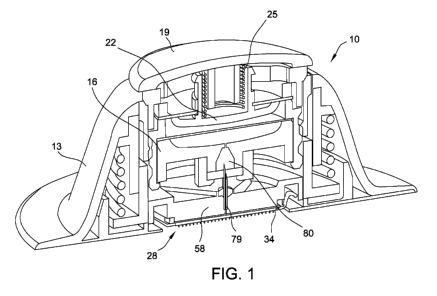
[0008] Fig. 1 is a cut-away view of a drug delivery device according to a
first
embodiment of this disclosure.
CA 03022463 2018-10-26
WO 2017/189258
PCT/US2017/027879
3
[0009] Fig. 2 is a detailed view of a portion of the device shown in Fig. 1.
[0010] Fig. 3 is a more detailed, schematic cross-sectional view of a portion
of a microneedle array assembly shown in Fig. 2.
[0011] Fig. 4 shows the emission pattern of a microneedle array without a
uniformity control membrane, as a comparative example.
[0012] Fig. 5 is a diagrammatic representation of a portion of micro needle
array assembly according to a second embodiment of this disclosure.
[0013] Fig. 6 is a graph that schematically illustrates how a suitably
configured uniformity control membrane may seek to advantageously diminish the
effects of
variations in bubble pressures associated with microneedles of a microneedle
array, in
accordance with the second embodiment.
DETAILED DESCRIPTION
[0014] Exemplary embodiments are described below and illustrated in the
accompanying drawings, in which like numerals refer to like parts throughout
the several views.
The embodiments described provide examples and should not be interpreted as
limiting the
scope of the invention. Other embodiments, and modifications and improvements
of the
described embodiments, will occur to those skilled in the art, and all such
other embodiments,
modification, and improvements are within the scope of the present invention.
[0015] In the following, a very brief and general initial
discussion of a drug
delivery device 10 of a first embodiment is followed by more detailed
discussions, such as more
detailed discussions of some of the separate subassemblies of the device 10.
Discussions
directed primarily to structural features of the device 10 are followed by
discussions more
specifically directed to methods of this disclosure.
[0016] Referring to Fig. 1, the device 10 is shown in a
partially activated
configuration. The device 10 may be characterized as including multiple main
subassemblies
that each may be self-contained. The main subassemblies may include a
receptacle 13, a
cartridge 16 or other suitable container or reservoir for being movably
mounted in the receptacle
13, and a mechanical controller 19 mounted to the cartridge 16.
CA 03022463 2018-10-26
WO 2017/189258
PCT/US2017/027879
4
[0017] The controller 19 can include a plunger 22 with, or alternatively
without, an internal force provider 25. The controller 19 is for applying
pressure to the reservoir
or cartridge 16 and, thereby, assisting in discharging of a liquid drug
formulation, or any other
suitable liquid formulation, from the cartridge 16 to a microneedle array 28.
[0018] The receptacle 13 of the first embodiment includes the microneedle
array 28. The microneedle array 28 includes a large number of microneedles 31
(Fig. 2) for
penetrating the user's skin, such as for providing a fluid that may be in the
form of a liquid drug
formulation into the user's skin. The microneedle array 28 may be more
generally referred to as
a device for engaging the skin of a patient or other user, and dispensing the
liquid formulation to
the user's skin, such as by dispensing the liquid formulation into the
epidermis portion of the
user's skin. In contrast to how the device 10 is shown in Fig. 1, it is
typical for at least a portion of
the microneedles 31 of the microneedle array 28 to be protruding outwardly
through a lower
opening of the receptacle 13. An example of the device 10 is further described
in U.S.
Provisional Patent Application Nos. 61/996,149, 61/996,156, 61/996,157, and
61/996,158, each
of which is incorporated herein by reference in its entirety.
[0019] As examples, the micro needle array 28 may be configured as
disclosed in one or more of WO 2012/020332 to Ross, WO 20111070457 to Ross, WO
2011/135532 to Ross, US 2011/0270221 to Ross, US 2013/0165861 to Ross, and
U.S.
provisional patent application number 61/996,148, each of which is
incorporated herein by
reference in its entirety. Generally, the microneedle array 28 of the device
10 may have any
suitable configuration known in the art for delivering a liquid formulation
onto, into, and/or through
the user's skin, such as by being configured to include the plurality of
microneedles 31 extending
outwardly from a suitable substrate or support, wherein this substrate or
support may be referred
to as a base or base plate 34. As shown in Fig. 3, the base plate 34 has a top
surface 37 (e.g.,
upstream side) and a bottom surface 40 (e.g. downstream side), and multiple
microneedles 31
extend outwardly from the bottom surface. The base plate 34 and microneedles
31 may
generally be constructed from a rigid, semi-rigid or flexible sheet of
material, such as a metal
material, a ceramic material, a polymer (e.g., plastic) material and/or any
other suitable material.
For example, the base plate 34 and microneedles 31 may be formed from silicon
by way of
reactive-ion etching, or in any other suitable manner.
CA 03022463 2018-10-26
WO 2017/189258
PCT/US2017/027879
[0020] The base plate 34 typically defines a plurality of passageways, which
may be referred to as holes or apertures 43, extending between the top and
bottom surfaces 37,
40 for permitting the liquid formulation to flow therebetween. For example, a
single aperture 43
may be defined in the base plate 34 proximate each microneedle 31. However, in
other
embodiments, the base plate 34 may define any other suitable number of
apertures 43
positioned at and/or spaced apart from the location of each microneedle 31. In
the first
embodiment, each aperture 43 leads to or includes a pair of downstream
openings or exit
openings 46 that are open to exterior channels 49 that are defined in and
extend along each of
the microneedles 31. Alternatively, each aperture 43 may extend through the
base plate 34 as
well as through the microneedle 31, as will be discussed in greater detail
below.
[0021] Each microneedle 31 of the microneedle array 28 may include a base
that extends downwardly from the bottom surface 40 and transitions to a
piercing or needle-like
shape (e.g., a conical or pyramidal shape or a cylindrical shape transitioning
to a conical or
pyramidal shape) having a tip 52 that is distant from the bottom surface 40.
The tip 52 of each
microneedle 31 is disposed furthest away from the base plate 34 and may define
the smallest
dimension (e.g., diameter or cross-sectional width) of each microneedle 31.
Additionally, each
microneedle 31 may generally define any suitable length L between its base and
its tip that is
sufficient to allow the microneedles 31 to penetrate the stratum corneum and
pass into the
epidermis of a user. It may be desirable to limit the length of the
microneedles 31 such that they
do not penetrate through the inner surface of the epidermis and into the
dermis, which may
advantageously help minimize pain for the patient receiving the liquid
formulation.
[0022] Each microneedle 31 may have a length L of less than about 1000
micrometers (um), such as less than about 800 um, or less than about 750 um,
or less than
about 500 um (e.g., a length ranging from about 200 um to about 400 um), or
any other sub-
ranges therebetween. In one specific example, the microneedles 31 may have a
length L of
about 290 um. The length of the microneedles 31 may vary depending on the
location at which
the device 10 is being used on a user. For example, the length of the
microneedles 31 for a
device 10 to be used on a user's leg may differ substantially from the length
of the microneedles
for a device 10 to be used on a user's arm. Each microneedle 31 may generally
define any
suitable aspect ratio (i.e., the length Lover a cross-sectional width
dimension W of each
microneedle 31). The aspect ratio may be greater than 2, such as greater than
3 or greater than
CA 03022463 2018-10-26
WO 2017/189258
PCT/US2017/027879
6
4. In instances in which the cross-sectional width dimension (e.g., diameter)
varies over the
length of each microneedle 31, the aspect ratio may be determined based on the
average cross-
sectional width dimension.
[0023] Each microneedle 31 may define the one or more exterior channels
49 in fluid communication with the apertures 43 defined in the base plate 34.
In general, the
exterior channels 49 may be defined at any suitable location on each
microneedle 31. For
example, the exterior channels 49 may be defined along an exterior surface of
each microneedle
31 as seen in Fig. 3. As a more specific example, each exterior channel 49 may
be an outwardly
open flute defined by the exterior surface of, and extending along the length
of, a microneedle
31. Alternatively and/or in addition, the channels 49 may be defined through
the interior of the
microneedles 31 such that each microneedle forms a hollow shaft, in which case
the aperture 43
and the interior channel may have the same diameter and be coaxial, as
generally discussed in
greater detail below. Regardless, the exterior channels 49 in combination with
the apertures 43
may generally be configured to form a downstream pathway that enables the
liquid formulation to
flow from the top surface 37 of the base plate 34, through the apertures 43
and into the channels
49, at which point the liquid formulation may be delivered onto, into, and/or
through the user's
skin. The exterior channels 49 may be configured to define any suitable cross-
sectional shape.
For example, each exterior channel 49 may define a semi-circular or circular
shape.
Alternatively, each exterior channel 49 may define a non-circular shape, such
as a "v" shape or
any other suitable cross-sectional shape.
[0024] The dimensions of the exterior channels 49 defined by the
microneedles 31 may be specifically selected to induce a capillary flow of the
liquid formulation.
The capillary pressure within an exterior channel 49 is inversely proportional
to the cross-
sectional dimension of the exterior channel and directly proportional to the
surface energy of the
subject liquid, multiplied by the cosine of the contact angle of the liquid at
the interface defined
between the liquid and the exterior channel. Thus, to facilitate capillary
flow of the liquid
formulation through the microneedle array 28, the cross-sectional width
dimension of the exterior
channel(s) 49 (e.g., the diameter of the exterior channel) may be selectively
controlled, with
smaller dimensions generally resulting in higher capillary pressures. For
example, the cross-
sectional width dimension of the exterior channels 49 may be selected so that,
with regard to the
width of each exterior channel 49, the cross-sectional area of each exterior
channel ranges from
CA 03022463 2018-10-26
WO 2017/189258
PCT/US2017/027879
7
about 1,000 square microns (um2) to about 125,000 um2, such as from about
1,250 um2 to about
60,000 um2, or from about 6,000 um2 to about 20,000 um2, or any other sub-
ranges
therebetween.
[0025] The microneedle array 28 may generally include any suitable number
of microneedles 31 extending from its base plate 34. For example, the actual
number of
microneedles 31 included within the microneedle array 28 may range from about
10 micro
needles per square centimeter (cm2) to about 1,500 microneedles per cm2, such
as from about
50 microneedles per cm2 to about 1250 microneedles per cm2, or from about 100
microneedles
per cm2 to about 500 microneedles per cm2, or any other sub-ranges
therebetween. The
microneedles 31 may generally be arranged on the base plate 34 in a variety of
different
patterns, and such patterns may be designed for any particular use. For
example, in some
embodiments, the microneedles 31 may be spaced apart in a uniform manner, such
as in a
rectangular or square grid or in concentric circles. In such embodiments, the
spacing of the
microneedles 31 may generally depend on numerous factors, including, but not
limited to, the
length and width of the microneedles 31, as well as the amount and type of
liquid formulation that
is intended to be delivered through or along the microneedles 31.
[0026] As best understood with reference to Fig. 2, at least a portion of the
micro needle array's base plate 34 may have a substantially rectangular
periphery that is in the
form of or includes a peripheral exterior channel 55 that (considering the
base plate in isolation)
is downwardly open and may have an overall substantially rectangular shape, or
any other
suitable shape. In the embodiment shown in Fig. 2, the microneedle array 28 is
mounted to a
backing structure 58 having inner and outer exterior channels 61, 64 that
(considering the
backing structure in isolation) are downwardly open and may have an overall
rectangular shape,
or any other suitable shape.
[0027] A substantially rectangular gasket 67 may be securely engaged in the
backing structure's inner exterior channel 61 and engaged securely against the
margin of at least
one uniformity control membrane 70 that is engaged against and covers the top
surface 37 of the
microneedle array 28. These secure engagements associated with the gasket 67
may result at
least partially from a frame 73 being fixedly mounted between the peripheral
exterior channel 55
of the microneedle array 28 and the outer exterior channel 64 of the backing
structure 58. The
CA 03022463 2018-10-26
WO 2017/189258
PCT/US2017/027879
8
frame 73 may be mounted between the peripheral and outer exterior channels by
way of one or
more mechanical connections such as an interference fit and/or any other
suitable fastening
technique. In the first embodiment, the microneedle array 28 is substantially
fixedly connected to
the backing structure 58 of the support assembly of the receptacle 14 by way
of the subject
connections.
[0028] The frame 73 may be characterized as being a substantially
rectangular bezel having substantially S-shaped cross-sections. The outer
peripheral edge of the
frame 73 may be press-fit into the outer exterior channel 64 so that the outer
peripheral edge of
the frame 73 is in compressing, opposing-face-to-face contact with a flange 76
that is part of or
otherwise associated with (e.g., partially defines) the outer exterior channel
64, and the inner
peripheral margin of the frame 73 is in compressing, opposing-face-to-face
contact with the
bottom surface 40 of the base plate 34. More specifically, the frame 73
engages against a
surface of the peripheral exterior channel 55 of the base plate 34.
[0029] Referring back to Fig. 1, the receptacle 13 further includes at least
one cannula 79 fixedly mounted to the backing structure 58 for moving
therewith. For example, a
lower portion of the cannula 79 may be fixedly mounted in a supply port
extending through the
backing structure 58 by way of one or more mechanical connections such as an
interference fit,
adhesive material and/or any other suitable fastening technique. The lower
open end of the
cannula 79 is in fluid communication with the upstream side of the uniformity
control membrane
70 (Fig. 2), and the upper open end of the cannula 79, which is typically
sharply pointed, extends
axially upwardly from the backing structure 58 for piercing a predetermined
portion of the
cartridge 16 to access the reservoir 80 therein.
[0030] The combination of at least the microneedle array 28 and the
uniformity control membrane 70 may be referred to herein as the microneedle
array assembly
71. At least the backing structure 58 and the microneedle array assembly 71
are cooperatively
configured so that a peripherally closed plenum chamber 82 (Fig. 3) is defined
therebetween.
The plenum chamber 82 is preferably hermetically sealed or closed, except for
being open to a
supply port such as provided by the cannula 79 extending through the backing
structure 58, and
being open to pores 85 (Fig. 3) of the uniformity control membrane 70.
CA 03022463 2018-10-26
WO 2017/189258
PCT/US2017/027879
9
[0031] During operation of the device 10 after it is configured as
substantially
shown in Fig. 1, the plunger 22 applies pressure to the cartridge 16 and the
liquid formulation
flows through the cannula 79 into the plenum chamber 82. The liquid
formulation exits the
plenum chamber 82 by flowing through pores 85 of the uniformity control
membrane 70, and
then the liquid formulation flows through the apertures 43 in the base plate
34 to the exterior
channels 49 associated with the microneedles 31 and into the user's skin.
[0032] Reiterating from above and as shown in Fig. 3, the top surface 37 of
the base plate 34 of the microneedle array 28 is covered with one or more
uniformity control
membranes 70 to at least partially form the microneedle array assembly 71. The
uniformity
control membrane 70 may be fabricated from permeable, semi-permeable or micro-
porous
materials configured for causing a pressure drop as the liquid formulation
flows therethrough. In
one example, at a predetermined flow rate with a predetermined drug
formulation, an appropriate
pressure drop across the uniformity control membrane 70 may be from 0.25kPa to
50kPa, from
10kPa to 10kPa, from 2.0 to 5.0kPa, from about 0.25kPa to about 50kPa, from
about 10kPa to
about 10kPa, from about 2.0 to about 5.0kPa, or any other subranges
therebetween.
[0033] The uniformity control membrane 70 can be schematically modeled as
having several discrete pores 85 for allowing the passage of liquid
formulation from the plenum
82 (at the upstream side of the uniformity control membrane) to the apertures
43 (at the
downstream side of the uniformity control membrane). In the first embodiment,
the collective
area of the pores 85 is less than the collective area of the apertures 43.
[0034] The uniformity control membrane 70 may be a track etched
membrane. Track etched membranes provide an advantage because passage of the
liquid
formulation is generally limited to the direction through the thickness of the
uniformity control
membrane 70 from one side to the other, substantially preventing spread of the
liquid formulation
within the uniformity control membrane in a in a lateral direction
perpendicular to the to the
thickness of the uniformity control membrane. A suitable track etched membrane
may be
available from Sterlitech Corporation of Kent Washington, USA, and may be in
the form of a 0.05
micron hydrophilic polycarbonate track etch membrane, or the like.
[0035] In the first embodiment, the uniformity control membrane 70 is
associated with the top surface 37 of the backing structure 34 in a matter
that limits or prevents
CA 03022463 2018-10-26
WO 2017/189258
PCT/US2017/027879
lateral movement of the liquid formulation between the uniformity control
membrane 70 and the
base plate 34. In other words, liquid formulation associated with (e.g.
proximate) one aperture 43
should be generally prevented from traveling over the top surface 37 into an
adjacent aperture
43. When the uniformity control membrane 70 is a track etched membrane, it may
have a
smooth side and a rough side. Generally it is preferred to have the smooth
side against the top
surface 37 to avoid the undesired lateral flow of liquid formulation.
[0036] The uniformity control membrane 70 may be intimately held to the top
surface 37 of base plate 34 by a pressing force applied by the frame 73 and
gasket 67 around
the periphery of the uniformity control membrane 70. During operation of the
device 10, liquid
pressure of the drug formulation within the plenum chamber 82 may be
sufficient to hold the
central area of the uniformity control membrane 70 against the top surface 37.
[0037] With reference back to Fig. 1, during operation of the device 10, the
liquid formulation may be forced out of the cartridge 16 by the plunger 22 and
the internal force
provider 25 of the controller 19 to cause the liquid formulation to
substantially uniformly fill the
plenum chamber 82 (Fig. 3) and substantially uniformly wet the uniformity
control membrane 70.
In other words and referring to Fig. 3, the liquid formulation typically
becomes available to each
aperture 43 at the top surface 37 of the base plate 34. Referring to Fig. 1,
the internal force
provider 25 (e.g. at least one spring) functions in connection with the
plunger 22 to provide
substantially complete emptying of liquid formulation from the cartridge 16
through the cannula
79 and into the plenum chamber 82. The plunger 22 and internal force provider
may provide a
force in a range of 1.1 N to 1.3 N, about 1.1 N to about 1.3 N, 2 N to 2.2 N,
about 2 N to about
2.2 N, 2.4 N to 2.6 N, about 2.4 N to about 2.6 N, 2.7 N to 2.9 N, about 2.7 N
to about 2.9 Nor
any other sub-ranges therebetween. The device 10 shown in Fig. 1 is provided
as an example
only. That is, the microneedle array assembly 71 may be used with or otherwise
incorporated
into any other suitable devices. For example, the plunger 22, force provider
25 and/or controller
19 may be replaced with other suitable features for forcing the liquid
formulation into the plenum
chamber 82, or the like.
[0038] The uniformity control membrane 70 may be selected so that the
pressure drop resulting from the liquid formulation passing through the
uniformity control
membrane consumes substantially all of the pressure energy imparted into the
liquid formulation
CA 03022463 2018-10-26
WO 2017/189258
PCT/US2017/027879
11
by way of the plunger 22 and internal force provider 25. For example, the
increase in pressure
provided by the plunger 22 and internal force provider 25 may have an absolute
value that is
approximately equal to the absolute value of the decrease in pressure provided
by the uniformity
control membrane 70. In accordance in a method of operation of the first
embodiment, the
pressure remaining immediately downstream from the uniformity control membrane
70 may be
only enough to cause or allow the liquid formulation to reach the channels 49
in a manner such
that there is capillary flow of the liquid formulation in the exterior
channels 49 of the microneedles
31.
[0039] Several variables should be considered together in order to produce
the potentially desired capillary flow. For example, the larger the force
applied by the plunger 22,
the higher the pressure through the cannula 79 and the higher the pressure of
the liquid
formulation within the plenum 82. In order to maintain the target flow rate,
the uniformity control
membrane 70 should be capable of an increased pressure drop to compensate for
the increased
pressure within the plenum 82. As a result, the uniformity control membrane 70
typically has a
resistance to flow that is selected in association with the plenum pressure
and the subsystem
that includes plunger 22 and force provider 25, if present.
[0040] Further regarding the microneedle array assembly 71 of the first
embodiment and as best understood with reference to Fig. 3, the microneedle
array assembly
has numerous compound flow paths that extend through the microneedle array
assembly, and
each compound flow path may be characterized as including an upstream flow
path and at least
one downstream flow path. For each compound flow path extending through the
microneedle
array assembly 71, the upstream flow path may consist of one or more
respective pores 85 of
the uniformity control membrane 70, so that each of the upstream flow paths
may be designated
by the numeral 85. For each compound flow path extending through the
microneedle array
assembly 71, the at least one downstream flow path may comprise, consist
essentially of, or
consist of a respective aperture 43 and a respective one or more exit or
downstream openings
46, so that each of the downstream flow paths may be designated by the
numerals 43, 46, or just
the numeral 43 for brevity. At least in theory, for each or a vast majority of
the compound flow
paths of the first embodiment, the downstream end of the upstream flow path 85
is in direct
communication with the upstream end of the respective downstream flow path 43
for preventing
lateral bypass flow, as generally discussed above.
CA 03022463 2018-10-26
WO 2017/189258
PCT/US2017/027879
12
[0041] As a first comparative example, Fig. 4 shows the downstream side of
the microneedle array 28, wherein the uniformity control membrane 70 is not
associated with the
upstream side of the micro needle array, and the downstream side of the
microneedle array is
discharging water at a relatively low pressure, such as by way of capillary
action, at a rate of
about 200 [11/hr. As shown in Fig. 4 for the first comparative example, even
though water is
uniformly applied to the entire upstream side of the microneedle array 28, the
water has flowed
through the microneedle array at only a small number of discrete locations, so
that the majority of
the area of the microneedle array remains dry on the downstream side thereof.
That is, Fig. 4
shows the water exiting out of a relatively small percentage of the downstream
flow paths 43,
such that the number of participating flow paths 43 is relatively small. This
suggests that, for the
first comparative example, there is a substantial lack of discharge uniformity
through the
microneedle array 28 and a greatly reduced efficiency of the broad application
site of the
microneedle array.
[0042] Manufacturing techniques typically limit the ability to form the
downstream openings of the downstream flow paths 43 with exactly the same
diameter or cross-
sectional area, which in some situations may result a substantial lack of
discharge uniformity,
such as the lack of discharge uniformity shown in Fig. 4. More specifically
regarding the fact that
manufacturing techniques may limit the ability to form the downstream openings
of the
downstream flow paths 43 with exactly the same diameter or cross-sectional
area, a bubble of
the liquid formulation exiting from a relatively large downstream flow path 43
will have a larger
bubble radius, and correspondingly, a smaller degree of surface tension, as
compared to a
bubble of the liquid formulation exiting from a relatively small downstream
flow path 43. The
energy required to add more liquid formulation to the larger bubble is less
than the energy
required to add liquid formulation to a smaller bubble pushing out from a
smaller downstream
flow path 43. In the first comparative example discussed above with reference
to Fig. 4, the large
bubble will grow slightly larger, and the pressure in that bubble decreases
further. The result is
that liquid formulation may flow through one or a few of the larger downstream
flow paths 43,
without flowing through the smaller downstream flow paths, even though the
smaller downstream
flow paths fully contain the liquid formulation.
[0043] In accordance with the first embodiment (e.g., in contrast to the
comparative example of Fig. 4), the uniformity control membrane 70 may be
adapted in a
CA 03022463 2018-10-26
WO 2017/189258
PCT/US2017/027879
13
manner that seeks to increase the discharge uniformity through the microneedle
array 28. For
example, at least the uniformity control membrane 70 and the microneedle array
28 are
cooperatively configured in a manner that seeks to allow the liquid
formulation to be substantially
uniformly administered across a relatively broad area and at a relatively low
pressure, such as by
way of capillary action, wherein the liquid formulation being substantially
uniformly administered
across the broad area comprises the liquid formulation steadily flowing
through and exiting out of
a relatively large percentage of the downstream flow paths 43, such that the
number of
participating downstream flow paths is relatively large. That is, the
uniformity control membrane
70 may be configured to provide improved efficiency of the useful area of the
microneedle array
28 relative to the first comparative example, by increasing the number of
participating
downstream flow paths 43 while maintaining a substantially similar target flow
rate and relatively
low administration pressure.
[0044] For each participating downstream flow paths 43, the liquid
formulation may steadily flow through and exiting out of the flow path. That
is, a participating
downstream flow path 43 through the microneedle array 28 is a downstream flow
path that has
liquid formulation flowing therethrough and exiting therefrom. Increasing the
number of
participating downstream flow paths 43 means increasing the percentage of the
downstream flow
paths from which liquid formulation is flowing for a predetermined target flow
rate and pressure.
By increasing the number of participating downstream flow paths 43,
administration of the liquid
formulation can be considered as being more uniform across the area of the
microneedle array
28. Because the body's response to a drug is area dependent, increasing the
uniformity of
discharge from the microneedle array 28 may improve the effectiveness of the
drug formulation
upon the body.
[0045] Using the uniformity control membrane 70 as herein described
provides unexpected and critical improvements to the number of participating
downstream flow
paths 43 of the microneedle array 28 at a predetermined target flow rate and
pressure. In this
regard, the uniformity control membrane 70 may have a resistance to flow
therethrough of at
least about 30 times greater than, at least about 40 times greater than, at
least about 50 times
greater than, between about 30 and about 100 times greater than, between about
40 and about
100 times greater than, or between about 50 and about 100 times greater than
the resistance to
flow through the microneedle array 28. These resistances to flow and
associated flow paths are
CA 03022463 2018-10-26
WO 2017/189258
PCT/US2017/027879
14
discussed in greater detail below, sometimes with reference to the first
embodiment, a second
embodiment of this disclosure, the first comparative example, and a second
comparative
example.
[0046] The second embodiment of this disclosure may be like the first
embodiment, except for variations noted and variations that will be apparent
to those of ordinary
skill in the art. Accordingly, reference numerals for features of the second
embodiment that at
least generally correspond to features of the first embodiment are incremented
by one hundred.
[0047] As diagrammatically shown in Fig. 5 for the second embodiment, each
downstream flow path 143 of the microneedle array 128 may alternatively or
optionally be in the
form of an interior channel, wherein the interior channels extend through the
interior of the
microneedles 131 such that each microneedle forms a hollow shaft. That is,
each downstream
flow path 143 of the second embodiment may comprise an interior channel and,
for example, the
exterior channels 49 of the first embodiment may be omitted.
[0048] As an example, when the microneedle array assembly 171 is in use
and the liquid formulation flows through the upstream flow paths 185 and
reaches the upstream
openings of the downstream flow paths 143, the liquid formulation will attempt
to enter the
upstream openings of the downstream flow paths 143. For example, when the
contact angle that
the liquid formulation makes with the downstream flow paths 143 is less than
90 degrees (e.g.,
when adhesive forces are stronger than the cohesive forces), the downstream
flow paths 143
may fill up to the downstream openings of the downstream flow paths due to the
due to capillary
action. At this point, the downstream opening of each downstream flow path 143
can be
generalized as having an independent boundary between the liquid formulation
and the air. The
boundary between a liquid (e.g., a liquid drug formulation) and a gas (e.g.,
air) has surface
tension. When that boundary between the liquid and the gas is deformed, there
is a change in
surface tension due to a change in the curvature of the surface formed at the
boundary. As the
liquid formulation is pushed outwardly from the downstream openings of the
downstream flow
paths 143, the liquid formulation is pushed into the air and drops or bubbles
of the liquid
formulation can form exiting each downstream openings of the downstream flow
paths. The
curvature of these bubbles is small at first, and grows as liquid formulation
flows through the
downstream flow paths 143. However, as alluded to above, in some situations
one of the exiting
CA 03022463 2018-10-26
WO 2017/189258
PCT/US2017/027879
bubbles of the liquid formulation may be larger than the other, such as due to
variations in sizes
of the downstream openings of the downstream flow paths 143, or for one or
more other
reasons.
[0049] Some aspects of the factors associated with the flow
of the liquid
formulation and associated bubbles may be understood with reference to the
theoretical system
of Fig. 5 and the equations and calculations presented below. For the purposes
of the following
equations and calculations, the plenum chamber 182 and upstream and downstream
flow paths
185, 143 are full of fluid, and there is a fluid/air interface at the
downstream openings of the
downstream flow paths. The flow through a first downstream flow path 143 is
Qi, and the flow
through a second downstream flow path 143 is Q2 . R1 represents any resistance
to flow
immediately upstream from the upstream openings of the upstream flow paths
185. R2 and R4
are the resistance to flow through the uniformity control membrane 170, or
more specifically the
resistance to flow through the upstream flow paths 185. R3 is the resistance
to flow through a
first downstream flow path 143, and R5 is the resistance to flow through a
second downstream
flow path 143. Pin is the pressure at the source. Pi and P4 respectively are
the pressures at the
upstream openings of the upstream flow paths 185. P2 and P5 respectively are
the pressures at
the upstream openings of the downstream flow paths 143. P3 and P6 respectively
are the
pressures at the downstream openings of the downstream flow paths 143.
[0050] The pressures P3 and P6 respectively at downstream openings of the
downstream flow paths 143 are typically neither constant nor zero. More
specifically, these
pressures P3 and P6 are respectively dependent on the shape of the fluid
exiting the downstream
openings of the of the downstream flow paths 143. In one example, the
pressures P3 and P6
(e.g., the bubble pressures) at the downstream openings of the downstream flow
paths 143 may
each be about 1200 Pa, which represents the pressure required to push fluid
out the
downstream opening of each downstream flow path and into the air.
[0051] The pressures P3 and P6 respectively at the downstream openings of
the downstream flow paths 143 may be calculated by the Young-Laplace equation
which relates
the surface tension, fluid curvature and pressure drop across the fluid/gas
interface, as indicated
below:
CA 03022463 2018-10-26
WO 2017/189258
PCT/US2017/027879
16
1,
Ap [0052] y (wr, 73 Equation I
[0053] In the above Young-Laplace equation, ri and r2 are the principle
radii
of curvature of a bubble of the liquid formulation exiting the downstream
opening of a
downstream flow path 143. The radii of curvature change with the amount of
fluid that has
flowed. At low volumes the curvature is small and the pressure is large. As
fluid flows the radius
increases and the pressure is reduced.
[0054] It is the reduced pressure mentioned in the immediately prior
sentence that may cause problems when attempting to administer liquid
formulations at a
relatively low pressure. For example, in the event that the downstream opening
of the first
downstream flow path 143 is slightly larger than the downstream opening of the
second
downstream flow path, the bubble pressure at the downstream opening of the
first downstream
flow path may be slightly less than the bubble pressure at the downstream
opening of the second
downstream flow path, so that the upstream liquid formulation may
preferentially flow into the first
downstream flow path. As a result, a large bubble of the liquid formulation at
the downstream
opening the first downstream flow path 143 may get larger, a small bubble of
the liquid
formulation at the downstream opening the second downstream flow path may get
smaller, and
the liquid formulation may flow through the first downstream flow path rather
than the second
downstream flow path. That is, the differences in bubble pressure may cause
low uniformity of
flow in microneedle array 128, as discussed above.
[0055] In accordance with one aspect of this disclosure, the uniformity
control
membranes 70, 170 may be configured in a manner that seeks to reduce the
effects of
differences in bubble pressure for optimizing the number of participating
downstream flow paths
43, 143 at a predetermined target flow rate and pressure. For example, the
uniformity control
membranes 70, 170 may be advantageously configured in a manner that seeks to
inhibit the
pressure at the upstream opening of a downstream flow path 43, 143 from
dropping substantially
in response to flow through an adjacent downstream flow path, so that the flow
through the
adjacent downstream flow path does not negatively influence flow through the
other downstream
flow path. This relationship between a pair of adjacent downstream flow paths
43, 143 may be
generally understood with reference the equations discussed below.
CA 03022463 2018-10-26
WO 2017/189258
PCT/US2017/027879
17
[0056] For the theoretical system of Fig. 5, the flow into the system is the
sum of the flows through the first and second downstream flow paths 143, as
indicated by the
following equation:
[0057] Qin Qi Q Equation 2
[0058] Flow is proportional to the pressure drop and inversely proportional to
the resistance. Accordingly, flow through first downstream flow path 143 may
be determined from
the following equation:
fit Equation 1
[0059]
[0060] Similarly, flow through the second downstream flow path 43 may be
determined from the following equation:
Equation 4
[0061]
[0062] From the foregoing equations, sets of equations relating pressure
drops, resistances, and flows may be produced and solved. For example, the
following table
represents values associated with a second comparative example that is based
upon Fig. 5 but
effectively does not include any uniformity control
Second Comparative Example
Input Data Set Calculated Data Set
Qin = 100 ul/hr Qi = 100.0 ul/hr
Pin= 1,533.3 Pa Q2 = 0.0 ul/hr
R1 = 2,000.00 Pa s/um3 P1 = 1,478 Pa
R2 = 0.00 Pa S/UM3 P2 = 1,478 Pa
R3 = 10,000.00 Pa S/UM3 P4 = 1,533 Pa
R4 = 0.00 Pa S/UM3 P5 = 1,533 Pa
P3 = 1,200.00 Pa
P6 = 1,533.33 Pa
[0063] In accordance with the first and second embodiment, the uniformity
control membranes 70, 170 may be configured in a manner that seeks to have the
pressure at
CA 03022463 2018-10-26
WO 2017/189258
PCT/US2017/027879
18
the upstream opening of one downstream flow path 43, 143 not change
substantially in response
to flow through an adjacent downstream flow path. In this regard, from the
equations set forth
above, an equation for determining P2 may be derived, and it is set forth
below:
PV.2ta i=ii2+1?4+R$1=1=1?:0" i=ii41.3r4 =
P2 = E'quation
[0064] ki.+R2+P?.+R44.,es
[0065] For determining how P2 changes as P6 changes, the above equation
may be simplified by assuming that R1 is equal to zero, R2 and R4 are equal to
one another, and
R3 and R5 are equal to one another, and the difference between P6 and H may be
represented
by [3, to produce the following simplified equation:
.R3 f (R24,123.i+ p)
P2 =", P3+ Equation6
[0066] 2c122 +R3)
[0067] From the above simplified equation, sets of equations may be
produced and solved, for calculating the relationship between P2 and the
resistance of the
uniformity control membrane 170 (i.e., R2) and deviations in pressure between
adjacent
downstream openings of downstream flow paths 143 (i.e., [3). For example,
Equation 6 may be
solved using an of 0.027 um3/s (i.e., 100 ul/hr), H of 1200 Pa, and R3 of
10,000 Pa s/um3,
wherein the calculated relationships are shown in Fig. 6, with the upright
axis (i.e., z-axis)
representing P2.
[0068] Fig. 6 schematically illustrates how suitably
configured uniformity
control membranes 70, 170 may seek to advantageously diminish the effects of
variations in
bubble pressures (e. g., [3, or more specifically variations between P3 and
Ps) at downstream
openings of downstream flow paths 143. For example and with reference to the
system of Fig. 5
and Equation 6, the rate of change of P2 as a function of differences between
bubble pressures
at adjacent downstream openings of downstream flow paths 143 (e.g., variations
between P3
and Ps, represented by [3) may be represented by the following equation:
a P2 R3
Equation 7
[0069] a a AP24 it3)
[0070] The foregoing equation provides insight into how a suitably configured
uniformity control membrane 70, 170 may seek to advantageously diminish the
effects of
CA 03022463 2018-10-26
WO 2017/189258
PCT/US2017/027879
19
variations in bubble pressures (e.g., [3, or more specifically variations
between P3 and Ps) at
downstream openings of downstream flow paths 143. For example, if bubble
pressures (e.g., [3,
or more specifically variations between H and Ps) at downstream openings of
downstream flow
paths 143 vary by up to 1200 Pa and it is desirable for the pressure P2 to
deviate by less than
1%, Equation 7 may be represented as follows:
d P2 410200
[0071] dp 2(R2+1a) Eq"at"' s
[0072] Equation 8 may be represented as shown below, for determining how
much larger R2 should be as compared to R3, or more generally how much larger
the resistance
to flow through the uniformity control membranes 70, 170 should be as compared
to the
resistance to flow through the microneedle arrays 28, 128.
AS I
[0073] Imo 2,114,k) EqUall 11
[0074] Solving Equation 9 results ink being 49; therefore, in this example, R2
should be at least about fifty times larger than R3, or more generally the
resistance to flow
through the uniformity control membranes 70 and 170 should be at least about
fifty times larger
than the resistance to flow through the microneedle arrays 28 and 128,
respectively. More
generally, the uniformity control membranes 70 and 170 may have a resistance
to flow
therethrough of at least about 30 times greater than, at least about 40 times
greater than, at least
about 50 times greater than, between about 30 and about 100 times greater
than, between about
40 and about 100 times greater than, or between about 50 and about 100 times
greater than the
resistance to flow through the microneedle arrays 28 and 128, respectively.
[0075] As alluded to above with reference to Fig. 5 and in accordance with
one example, the pressures H and P6 (e.g., the bubble pressures of the fluid
formulation) at the
downstream openings of each of the downstream flow paths 43, 143 may be about
1200 Pa,
which may represent the pressure required to push the fluid formulation out
the downstream
opening of the downstream flow path and into air. In examples of methods of
operation, the
pressure drop across the uniformity control membranes 70 and 170 may be at
least about 30
times greater than, at least about 40 times greater than, at least about 50
times greater than,
between about 30 and about 100 times greater than, between about 40 and about
100 times
CA 03022463 2018-10-26
WO 2017/189258
PCT/US2017/027879
greater than, or between about 50 and about 100 times greater than the
pressure required to
push the fluid formulation out the downstream openings of the downstream flow
paths 43, 143
and into air. The pressure required to push the fluid formulation out the
downstream openings of
the downstream flow paths 43, 143 and into air may be generally referred to as
the bubble
pressures of the microneedle arrays 28 and 128. Accordingly, the pressure
drops across the
uniformity control membranes 70 and 170 may be at least about 30 times greater
than, at least
about 40 times greater than, at least about 50 times greater than, between
about 30 and about
100 times greater than, between about 40 and about 100 times greater than, or
between about
50 and about 100 times greater than the bubble pressures of the microneedle
arrays 28 and 128,
respectively.
[0076] As alluded to above, for each compound flow path extending through
the microneedle array assemblies 71, 171, the downstream openings of the
upstream flow paths
85, 185 may be in direct communication with the upstream openings of the
downstream flow
paths 43, 143, for example as a result of the uniformity control membranes 70,
170 being
securely engaged against the upstream sides of the microneedle arrays 28, 128.
In accordance
with one aspect of this disclosure and at least partially reiterating from
above, the resistance to
flow through the upstream flow paths 85, 185 may be substantially higher than
the resistance to
flow through the downstream flow paths 43, 143, wherein these differences in
flow resistance
seek to facilitate, for example, the uniform administration of the liquid
formulation into the
patient's skin across a broad area and at a relatively low pressure, such as
by way of capillary
action. The administration of the liquid formulation into the patient's skin
across the broad area
may comprise the liquid formulation being administered by way of at least a
majority of the
downstream flow paths 43, 143, such that the liquid formulation is
administered by way of at
least a majority of the microneedles of the microneedle arrays 28, 128.
[0077] That is, the uniformity control membranes 70, 170 may have the effect
of significantly increasing the overall resistance to flow through each
compound flow path (e.g.,
upstream flow paths 85, 185 together with downstream flow paths 43, 143) in a
manner that
minimizes differences in overall flow resistance among the numerous compound
flow paths. As a
result, the liquid formulation may actively utilize (i.e. flow through) an
increased number of the
compound flow paths when the liquid formulation is administered at a low
pressure, such as a
pressure that is low enough so that a substantial portion of the liquid
formulation is administered
CA 03022463 2018-10-26
WO 2017/189258
PCT/US2017/027879
21
by way of capillary action. That is, the number of participating compound flow
paths may be
increased to provide a larger area of administration of the liquid formulation
at low pressure. The
liquid formulation being administered by way of at least a majority of the
downstream flow paths
43, 143 may comprise the liquid formulation being administered by way of at
least about 50%, at
least about 60%, at least about 70%, at least about 80% or at least about 90%
of the
downstream flow paths 43, 143.
[0078] In one aspect of this disclosure, when the liquid
formulation is initially
supplied to the upstream openings of the upstream flow paths 85, 185 and fills
the compound
flow paths, outwardly protruding bubbles of the liquid formulation may form at
the downstream
openings of the downstream flow paths 43, 143, and these bubbles contribute to
the resistance
to flow through the downstream flow paths 43, 143. In one example, the bubbles
of the liquid
formulation may be globules of the liquid formulation in the ambient
atmosphere or environment,
such as a thin layer of air covering a portion of a patient's skin where the
liquid formulation is to
be administered, or the like. Further regarding the outwardly protruding
bubbles of the liquid
formulation that initially form at the downstream openings of the downstream
flow paths 43, 143,
relatively small bubbles may form at some of the downstream openings, and
relatively large
bubbles may form at other of the downstream openings. The pressure of the
liquid formulation in
the relatively small bubbles is larger than the pressure of the liquid
formulation in the relatively
large bubbles, such that the resistance to flow due to the small bubbles is
greater than the
resistance to flow due to the large bubbles. At least in theory, the
resistance to flow through the
uniformity control membranes 70, 170 may be sufficiently large so that the
pressure drop through
the upstream flow path 85, 185 of a compound flow path with a relatively large
and expanding
bubble may exceed the pressure drop in the upstream portion of a compound flow
path with a
relatively small bubble. In this regard, the pressure drop in the upstream
portion of the compound
flow path with the relatively large and expanding bubble may exceed any
pressure drop in the
upstream portion of the compound flow path with the relatively small bubble in
a manner that
substantially equalizes the flow through the compound flow paths, so that a
majority of the
bubbles that form at the downstream openings of the downstream portions of the
compound flow
paths rupture and are replaced with a constantly outwardly flowing stream of
the liquid
formulation.
CA 03022463 2018-10-26
WO 2017/189258
PCT/US2017/027879
22
[0079] The above examples are in no way intended to limit the scope of the
present invention. It will be understood by those skilled in the art that
while the present disclosure
has been discussed above with reference to exemplary embodiments, various
additions,
modifications and changes can be made thereto without departing from the
spirit and scope of
the invention, some aspects of which are set forth in the following claims.