Note: Descriptions are shown in the official language in which they were submitted.
TITLE
[0001] METHANATION OF ANODE EXHAUST GAS TO ENHANCE CARBON
DIOXIDE CAPTURE.
BACKGROUND
[0002] The present disclosure relates to fuel cell power production systems
and, in particular,
to a fuel cell power producing gas separation system and method.
[0003] A fuel cell is a device which directly converts chemical energy
stored in a fuel into
electrical energy through electrochemical reactions. Generally, a fuel cell
comprises an anode
and a cathode separated by an electrolyte, which serves to conduct
electrically charged ions.
Molten Carbonate Fuel Cells (MCFCs) operate by passing a reactant fuel gas
through the anode,
while oxidizing gas, such as carbon dioxide and oxygen, is passed through the
cathode.
Combustion-based power plants produce energy by combusting flammable
hydrocarbon based
fuels including coal, natural gas, biogas, and syngas.
[0004] As a result of the combustion process, combustion-based power plants
generate flue
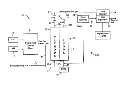
gas, which is often disposed of by atmospheric emissions. Such emissions,
however, are harmful
to the environment because they contain carbon dioxide (CO2) which contributes
to global
climate change. Increasing national and international regulations are placing
strict regulations on
the amount of CO2 which may be released in the environments by such power
generation
systems.
[0005] Accordingly, a number of approaches have been used to control or
limit carbon
dioxide emissions from combustion-based power plants. However, separating the
carbon
dioxide from the post-combustion flue gas is highly expensive because of the
significant loss of
energy (power and/or heat) as the result of application of carbon dioxide
capture systems to
dilute CO2 containing flue gas. The flue gas including the carbon dioxide may
be provided to an
electrochemical fuel cell which may include a cathode, an anode and an
electrolyte, for
CA 3022534 2020-03-17
CA 03022534 2018-10-29
WO 2017/189238 PCMJS2017/027261
concentrating the carbon dioxide in the anode exhaust gas. The anode exhaust
gas including the
carbon dioxide from the flue gas may be communicated to a compressor,
condenser and/or
chiller to liquefy and separate the carbon dioxide from the other gases
included in the anode
exhaust gas. Hydrogen gas and other non-condensible gases included in the
anode exhaust gas
will, however, hamper capturing of the carbon dioxide and increase the cost of
compression
and/or condensation via refrigeration (e.g., by increasing the energy used for
compression and/or
condensation) or reducing the amount of CO2 captured.
SUMMARY
[0006] Embodiments described herein generally relate to systems and methods
for capturing
carbon dioxide by use of fuel cell systems, and in particular to a fuel cell
power producing gas
separation system that may be integrated with a fossil fuel device, facility
or installation (e.g., a
power plant, boiler or any other combustor such as kilns in a cement factory
and coke ovens in
the steel industry) configured to efficiently separate various gases included
in a flue gas,
particularly carbon dioxide. The hydrogen included in the fuel cell anode
exhaust gas is
methanated so as to increase the relative concentration of carbon dioxide in
the anode exhaust
gas and reduce the volume of water separated anode exhaust gas.
[0007] In some embodiments, a fuel cell power producing system is
configured to be
integrated with a fossil fueled installation so as to utilize flue gas
produced by the fossil fueled
installation. The flue gas includes carbon dioxide and oxygen output by the
fossil fueled
installation. The power producing system includes an anode section and a
cathode section. The
flue gas containing carbon dioxide is communicated to the cathode section of
the fuel cell. The
anode section produces an anode exhaust gas including carbon dioxide, water,
hydrogen, carbon
monoxide and other gases. The anode exhaust gas is communicated to a gas
separation
assembly. The gas separation assembly includes a methanator configured to
convert at least a
portion of hydrogen included in the anode exhaust gas to methane so as to
generate a methanated
anode exhaust gas. The methanated anode exhaust gas has a higher ratio of
carbon dioxide to
non-condensable gases relative to a non-methanated exhaust gas.
[0008] In some embodiments, the gas separation assembly may include a
chiller assembly
for cooling the anode exhaust to a predetermined temperature so as to liquefy
carbon dioxide in
CA 03022534 2018-10-29
WO 2017/189238 PCT/US2017/027261
the methanated anode exhaust. In some embodiments, waste heat produced by the
fuel cell is
utilized to drive the chiller assembly. In some embodiments, the inlet flue
gas supplied to the
cathode section of the fuel cell contains exclusively all or part of the flue
gas output by the fossil
fueled installation, facility or device. In certain embodiments, the chiller
assembly may include
one or more chillers or knock out pots. In some embodiments, the gas
separation assembly
recovers waste heat from cathode exhaust output by the cathode section of the
fuel cell and
utilizes at least a portion of the recovered waste heat to drive the chiller
assembly.
[0009] In some embodiments, the gas separation assembly further includes a
water removal
assembly for separating water from the anode exhaust and for outputting water-
separated anode
exhaust, and the chiller assembly receives the water-separated anode exhaust.
The gas
separation assembly further includes a compressor for compressing the water-
separated anode
exhaust output from the water removal assembly prior to the water-separated
anode exhaust
being conveyed to the chiller assembly.
[0010] In some embodiments, the gas separation assembly is configured to
receive a
methanated anode exhaust gas from the power producing system. The compressor
may
compress the methanated anode exhaust gas to at least 250 psi (about 1.72 MPa)
and the chiller
assembly chills the methanated anode exhaust gas to less than -40 C. The
methanated anode
exhaust gas causes the gas separation assembly to provide a 10-20% increase in
carbon dioxide
capture and greater than a 20% decrease in compressor power, which includes
the power
required to operate the compressor assembly, relative to the gas separation
assembly operating
on non-methanated anode exhaust gas.
[0011] In some embodiments, the power producing system also includes an
oxidizer that
receives flue gas output by the fossil fueled installation, facility or device
and at least part of the
residual fuel gas separated by the gas separation device. The oxidizer
oxidizes the residual fuel
to heat the flue gas, where the oxidizer outputs heated flue gas to the
cathode section of the fuel
cell. In some embodiments, part of the residual fuel is recycled to the anode.
The power
producing system also includes at least one heat exchanger for utilizing waste
heat in the cathode
exhaust for heating at least one of fuel gas to be input to the anode section
and flue gas output by
the fossil fueled installation, facility or device. In some embodiments, the
fuel cell is an internal
3
CA 03022534 2018-10-29
WO 2017/189238 PCT/US2017/027261
reforming Molten Carbonate Fuel Cell (MCFC), while in other embodiments the
fuel cell is an
external reforming MCFC.
[0012] In some embodiments, a non-methanated anode exhaust gas includes 20-
25 mole%
hydrogen and other non-condensable gases and 65-75 mole% of carbon dioxide
inclusive, and
the methanated anode exhaust gas includes about 5-10 mole% of hydrogen and
other non-
condensable gases and 75-85 mole% of carbon dioxide.
[0013] These and other advantageous features will become apparent to those
reviewing the
disclosure and drawings.
BRIEF DESCRIPTION OF THE DRAWINGS
[0014] FIG. IA is a schematic illustration of a fuel cell, according to an
embodiment.
[0015] FIG. 1B is a schematic illustration of a power production system,
according to an
embodiment.
[0016] FIG. 2 is a schematic illustration a power producing system, and an
embodiment of a
gas separation assembly including a methanator fluidly coupled to the power
production system.
[0017] FIG. 3 is a schematic illustration of another embodiment of a gas
separation
assembly.
[0018] FIG. 4 is a plot showing heat curves of a heat exchanger included in
the gas
separation assembly of FIG. 3.
[0019] FIG. 5 is a schematic flow diagram of an example method for
increasing a
concentration of carbon dioxide in an anode exhaust gas by methanating at
least a portion of the
hydrogen included in the exhaust gas.
DETAILED DESCRIPTION
[0020] Embodiments described herein generally relate to systems and methods
for capturing
carbon dioxide produced by fuel cell systems, and in particular to an
integrated power production
system or fuel cell system that may be integrated with a fossil fuel device,
facility or installation
4
CA 03022534 2018-10-29
WO 2017/189238 PCT[US2017/027261
(e.g., a power plant, boiler or any other combustor such as kilns in a cement
factory and coke
ovens in the steel industry). The systems and methods described herein are
configured to
efficiently separate various gases included in an anode exhaust gas,
particularly carbon dioxide.
The hydrogen included in the anode exhaust gas is methanated so as to increase
a relative
concentration of carbon dioxide in the anode exhaust gas.
[0021] As used herein, the term "methanation" or "methanated" refers to the
conversion of at
least a portion of hydrogen and CO2 included in an anode exhaust gas to
methane.
[0022] FIG. 1 A is a schematic illustration of a fuel cell 1. The fuel cell
1 comprises an
electrolyte matrix 2, an anode 3, and a cathode 4. The anode 3 and the cathode
4 are separated
from one another by the electrolyte matrix 2. Flue gas from a combustion
exhaust supply unit
may be provided to the cathode 4 as oxidant gas. In the fuel cell 1, in the
cathode, CO2 and 07 in
the form of CO3= ions are transferred from the cathode to the anode and in the
anode, fuel gas
and oxidant gas undergo an electrochemical reaction in the presence of an
electrolyte (e.g., a
carbonate electrolyte) present in the pores of the electrolyte matrix 2.
[0023] In some embodiments, the fuel cell 1 may comprise a fuel cell stack
assembly in
which multiple individual fuel cells 1 are stacked and connected in series.
FIG. 1B is a
schematic illustration of an integrated power production system 100 according
to an
embodiment. The power production system 100 comprises a flue gas generating
assembly 6,
which includes one or more of a fossil fueled installation, facility or
device, a boiler, a
combustor, a furnace and kiln in a cement factory (hereinafter "fossil fueled
installation, facility
or device"). The flue gas generating assembly may be configured to burn a
fossil fuel (e.g., coal,
natural gas, gasoline, diesel, etc.) and produce a flue gas including carbon
dioxide.
[0024] The power production system 100 includes a fuel cell assembly 10
(e.g., a carbonate
fuel cell assembly) fluidly coupled to the flue gas generating assembly 6 and
configured to
receive the flue gas therefrom. The power production system 100 also includes
a power
producing gas separation and sequestration system that includes a carbonate
fuel cell assembly
and a gas separation assembly 25 in accordance with illustrative embodiments.
As shown in
FIG. 1B, the fuel cell assembly 10 includes a cathode section 12 and an anode
section 14. In
some embodiments, the fuel cell assembly 10 may include an internally
reforming or a direct
5
CA 03022534 2018-10-29
WO 2017/189238 PCT/US2017/027261
molten carbonate fuel cell assembly in which the fuel for the anode is
internally refolined in the
assembly. In other embodiments, the fuel cell assembly 10 may include an
externally reforming
carbonate fuel cell assembly can also be employed in which case a reformer
would be used to
refoim the fuel prior to delivery to the fuel cell anode section.
[0025] The flue gas generation assembly 6 and the fuel cell assembly 10 of
the power
producing gas separation and sequestration system may be arranged in tandem as
shown in FIG.
1B such that the cathode section 12 of the fuel cell assembly 10 is supplied
with the flue gas
from the flue gas generation assembly 6. In some embodiments, the flue gas
from the flue gas
generation assembly is supplied exclusively to the cathode section 12. For
example, a fossil fuel
such as coal, natural gas or other hydrocarbon fuel is delivered to the fossil
fueled installation,
facility or device 6 from a fossil fuel supply 2 along with air delivered from
an air supply 4. The
fossil fuel and air may undergo a combustion reaction in the flue generation
device 6 producing
power and resulting in an output flue gas exhaust. The flue gas exhaust may
comprise
approximately 3-15% carbon dioxide, 1-20% water (preferably 10-20%), and 3-15%
oxygen
(preferably 5-15%), with the balance nitrogen. The exact amounts of these
components depends
upon the type of fossil fuel and the amount of air from the air supply 4. The
oxygen content can
be varied by adjusting the air supply 4 or by addition of supplementary air 7
to the flue gas 8
before entering in the fuel cell cathode section 12. The supplementary air may
be used to
increase the oxygen portion of the combined stream 9, in case there is not
sufficient oxygen in
the flue gas 8 required for the fuel cell operation.
[0026] As shown in FIG. 1B, a line 9 fluidly couples a part or all of the
flue exhaust gas to
the inlet 12A of the cathode section 12 so that the flue gas or oxidant gas
supply to the cathode
inlet 12A includes the flue gas exhaust. In some embodiments, the flue gas in
combination with
a possible supplementary air stream is the exclusive oxidant gas supply to the
cathode inlet 12A.
At the same time, fuel from a supply 16, such as coal gas, natural gas or
other hydrogen-
containing fuel, is delivered over a line 15 to an inlet 14A of the anode
section 14. In the fuel
cell assembly 10, the oxidant gas in the cathode section 12 comprising flue
gas exhaust and the
reformed hydrogen in the anode section 14 undergo an electrochemical reaction
to produce a
power output. Also, this electrochemical reaction results in a substantial
portion (approximately
6
CA 03022534 2018-10-29
WO 2017/189238 PCT/1JS2017/027261
65 to 85% or more) of the carbon dioxide in the flue gas being transferred
from the cathode
section 12 to the anode section 14 of the fuel cell 10.
[0027] Expanding further, the carbon dioxide and oxygen in the flue gas
react in the cathode
section 12 of the fuel cell assembly 10 to produce carbonate ions which are
carried to the anode
section 14 of the fuel cell 10 through the fuel cell electrolyte. At the anode
section 14, the
carbonate ions are reduced with hydrogen from the fuel to produce water and
carbon dioxide.
The net result is the above-mentioned transfer of a substantial portion of the
carbon dioxide in
the flue gas from the cathode section 12 to the anode section 14. Anode
exhaust gas at the outlet
14B of the anode section 14 of the fuel cell 10 is thus, high in concentration
of carbon dioxide,
thereby permitting the carbon dioxide gas to be more easily and efficiently
captured and
sequestered using the CO, separation and sequestration systems described
herein. In some
embodiments, a concentration of carbon diode in the anode exhaust gas in range
of 60-75 mole%
(dry basis) inclusive of all ranges and values therebetween. In alternative
embodiments, a higher
concentration may be achieved.
[0028] In the embodiment shown in FIG. 1B, flue gas depleted of carbon
dioxide exits the
cathode section 12 through a cathode outlet 12B via a line 18, and anode
exhaust gas containing
predominantly carbon dioxide as well as unreacted hydrogen, carbon monoxide,
water vapor and
trace amounts of other gases exits the anode outlet 14B and is conveyed by
line 20 to the gas
separation assembly 25. In some embodiments, the gas separation assembly 25
may include at
least a water removal assembly 21 for recovering water from the anode exhaust
and a carbon
dioxide separation assembly 22 for separating carbon dioxide from the
remaining anode exhaust
gas. Moreover, because the cathode gas exits the fuel cell assembly 10 at high
temperature, all
or part of the detectable heat from this stream may be recovered by one or
more heat recovery
units 17 and may be used for pre-heating gases incoming into the fuel cell
assembly 10. In some
embodiments, heat may be recovered from the anode exhaust gas exiting the fuel
cell anode
section 14 prior to being conveyed to the gas separation assembly 25.
[0029] FIG. 2 is a more detailed schematic illustrations of the power
producing gas
separation and sequestration system 200, according to an embodiment. The
system 200 receives,
flue gas from a combustion exhaust supply 205 (e.g., the flue gas generation
assembly 6). The
7
CA 03022534 2018-10-29
WO 2017/189238
PCT/US2017/027261
flue gas mainly contains carbon dioxide, water, oxygen and nitrogen, and may
be produced from
combustion of flammable hydrocarbons, including, for example, coal, natural
gas, biogas,
syngas, and other hydrocarbonaceous fuels such as ethanol, in a combustion-
based power plant, a
fossil fueled installation, facility or device or the like. The combustion
exhaust supply 205
supplies the flue gas exhaust through a gas stream conduit 210a to a trace
contaminant/pollutant
gas removal device 215. The trace contaminant/pollutant gas removal device 215
removes
combustion by-products including sulfur oxide gases, such as SO2, mercury, and
particulates.
Nitrogen oxide gases (N0x) need not be removed since they do not impact the
performance of
fuel cell and most of the NOx will be destroyed in the fuel cell cathode. As
shown in FIG. 2, the
trace contaminant/pollutant gas removal device 215 outputs cleaned flue gas to
a flue gas blower
220 through the gas stream conduit 210b. The flue gas blower 220 boosts the
pressure of the
cleaned flue gas such that the flue gas is pushed through the system 200.
[0030] The flue
gas blower 220 outputs the flue gas to a first heat exchanger 225, which is
configured to heat the flue gas to a temperature of approximately 500 C - 650
C. In some
embodiments, the first heat exchanger 225 may also remove heat from the flue
gas and divert the
heat for heat recovery. As shown in FIG. 2, the first heat exchanger 225
receives the cleansed
flue gas from the combustion exhaust supply 205 through the gas stream conduit
210b and also
receives cathode exhaust output from a cathode side 236 of the fuel cell 235.
After the flue gas
is heated to the desired temperature in the first heat exchanger 225, the
heated flue gas is output
to an oxidizer assembly including- an oxidizer 230. The oxidizer 230 also
receives gas containing
fuel, such as a portion of the anode exhaust or all or a portion of residual
fuel separated from the
anode exhaust gas in a gas separation device 275 described herein below. In
some embodiments,
it also receives part of the natural gas feed 241. In the oxidizer 230, fuel
containing gas is
oxidized in the presence of flue gas, thereby further heating the flue gas.
The oxidizer 230
outputs the further heated flue gas through the gas stream conduit 210c to the
fuel cell 235.
[0031] The fuel
cell 235 comprises the cathode section 236 and the anode section 237. The
fuel cell 235 may include an internal reforming Molten Carbonate Fuel Cell
(MCFC), an external
reforming fuel cell, or a combination thereof for reforming the fuel before it
is conveyed to the
anode section 237. The cathode section 236 is coupled to the combustion
exhaust supply 205 via
the gas stream conduits 210a-c and receives the flue gas from the combustion
exhaust supply 205
8
CA 03022534 2018-10-29
WO 2017/189238 PCT/US2017/027261
through the gas stream conduits 210b-c after the flue gas has been processed
in the trace
contaminant/pollutant gas removal device 215 and heated in the first heat
exchanger 225 and the
oxidizer 230. As shown in FIG. 2, the cathode section 236 receives exclusively
the flue gas, or
processed flue gas, provided from the combustion exhaust supply 205. However,
in other
embodiments, the flue gas or the processed flue gas may be mixed with air or
oxidant gas from
other sources.
[0032] After undergoing an electrochemical reaction in the fuel cell 235,
the cathode section
236 outputs the cathode exhaust through a gas stream conduit 212 to a second
heat exchanger
240 which also receives fuel, such as natural gas, from a fuel supply 241 and
water 252 through a
fuel supply conduit 242. Any suitable fuel may be used including but not
limited to natural gas,
coal-derived syngas, anaerobic digester gas, and renewable fuels such as
ethanol or hydrogen. In
some embodiments, harmful fuel cell contaminants such as sulfur-bearing
species may be
removed from the fuel gas before usage in the fuel cell 235. In the second
heat exchanger 240,
the received fuel is heated using waste heat from the cathode exhaust to a
temperature of
approximately 450 ¨ 650 degrees Celsius, and heated fuel and steam is then
conveyed from the
second heat exchanger 240 to the anode section 237 of the fuel cell 235. The
second heat
exchanger 240 also outputs cooled cathode exhaust which is then conveyed
through the first heat
exchanger 225 to pre-heat the cleaned flue gas.
[0033] As shown in FIG. 2, the anode section 237 receives pre-heated fuel,
which may be
humidified by adding water via conduit 252, and after the gases undergo an
electrochemical
reaction in the fuel cell 235, the anode section 237 outputs anode exhaust gas
to the gas
separation assembly 25 via a conduit 214. The gas separation assembly 25
includes a methanator
245, a water removal assembly 250, a compressor 260 and a carbon dioxide
separation assembly
22, includin2, a chiller assembly 265 driven by waste heat of the fuel cell
235 and a flash drum
275 or another suitable gas-liquid separation device. Although not shown,
partial coolina, of the
anode exhaust gas is required prior to entering the methanator as lower
temperatures favor the
equilibrium formation of methane. Because the methanation reaction is
exothermic, multiple
methanators with cooling between stages may be used.
9
CA 03022534 2018-10-29
WO 2017/189238 PCT/US2017/027261
[0034] The methanator 245 is configured to convert at least a portion of
the hydrogen included
in the anode exhaust gas to methane via the following reactions;
4117 + CO, ---> CH4+ 2Th0 ---(1)
2H2 + CO ---> CH4+ H70 ---(2)
which produces a methanated anode exhaust gas, i.e., an anode exhaust gas
having a higher
percentage of methane and a lower percentage of hydrogen. This leads to the
exhaust gas having
a lower total volume, especially after the water is condensed and removed and
a higher
concentration of carbon dioxide relative to the non-condensables in the anode
exhaust gas.
[0035] Expanding further, the hydrogen and other non-condensable gases
present in the
anode exhaust gas interfere with the concentration of carbon dioxide by the
fuel cell anode
exhaust which may also lead to increased cost of compression and chilling of
the carbon dioxide
downstream of the fuel cell. Methanating the hydrogen included in the anode
exhaust gas
reduces 4 moles of inert hydrogen into 1 mole of inert methane. Because anode
exhaust gas
generally includes hydrogen + carbon monoxide in the range of about 25% and
about 75%
carbon dioxide on a dry basis, this increases the percent concentration of
carbon dioxide in the
anode exhaust gas from about 75% to about 85% and reduces the volume of the
anode exhaust
gas by approximately 15%. In some embodiments, methanating the anode exhaust
gas may
increase a concentration of carbon dioxide in the anode exhaust gas in the
range of 10-20%
inclusive of all ranges and values therebetween.
[0036] The methanator 245 may have any suitable configuration and/or
structure and may
include a catalyst formulated to promote conversion of hydrogen to methane.
Suitable catalysts
may include but are not limited to ruthenium, cobalt, nickel, iron, any other
suitable catalyst or a
combination thereof. The methanator 245 may be a single stage or a multiple
stage methanator.
The methanated anode exhaust gas from the methanator 245 is then conveyed to
the water
removal assembly 250, including a condenser or the like, where water present
in the methanated
anode exhaust gas is separated from the remaining gases through condensation.
[0037] The water removal assembly 250 outputs condensed water through a
water removal
conduit 251 from which the condensed water is recycled back to the system 200
or output to a
CA 03022534 2018-10-29
WO 2017/189238 PCT/US2017/027261
product water collector 255 for use outside the system 200 and/or recycling
back to the system.
As shown in FIG. 2, all or a portion of the condensed water may be recycled
for fuel
humidification by routing the water to the fuel supply conduit 242 via the
water recycling
conduit 252. As also shown, the remaining portion of the condensed water is
either output from
the system 200 or collected in a product water collector 255 and may be
recycled back to the
system 200 when needed.
[0038] The condenser assembly 250 outputs water-separated anode exhaust
through the gas
stream conduit 216 to the compressor 260, which compresses the anode exhaust
gas to a suitable
pressure¨for example, a pressure of about 200 psi (or 1.38 MPa) or higher. The
higher the
pressure of the compressor 260, the higher the temperature that can be offered
by the chiller.
The design points are a trade-off between a larger and more cooling chiller
and higher
compression power consumption. The compressor 260 outputs the compressed anode
exhaust to
the chiller assembly 265. In some embodiments, the compressor 260 is a
multiple stage
compressor with interstage cooling. The chiller assembly 265 may include one
or more devices
that use heat to drive cooling of the compressed water-separated anode exhaust
so as to cause
separation of the individual gases within the anode exhaust. As shown in FIG.
2, the chiller
assembly 265 comprises one or more absorption chillers, i.e., one or more
absorption
refrigerators. In some embodiments, an assembly of a plurality of absorption
chillers connected
in series may be used, wherein each of the absorption chillers receives all or
a portion of the
compressed water-separated anode exhaust from the compressor 260.
[0039] In the chiller assembly 265, water-separated compressed anode
exhaust gas is cooled
to a predetermined temperature while maintaining its compressed state. In
particular, the anode
exhaust gas is cooled to a temperature of about -40 C or cooler, while
maintaining the high
pressure of the gas, i.e., at about 200 psi (about 1.38 MPa) or higher. At
this temperature and
pressure, most of the carbon dioxide present in the anode exhaust is liquefied
causing separation
of the carbon dioxide from other gases, such as residual hydrogen and methane
fuel present in
the anode exhaust gas. The higher CO, concentration, resulting from
methanation, increases the
amount of CO2 liquefied. The chiller assembly 265 utilizes waste heat
generated by the fuel cell
237 and recovered from fuel cell exhaust in a heat recovery assembly 270.
Specifically, cathode
exhaust is conveyed to the heat recovery assembly 270 via conduit 266 after
being passed
11
CA 03022534 2018-10-29
WO 2017/189238 PCT/US2017/027261
through the second heat exchanger 240 and through the first heat exchanger
225. The heat
recovery assembly 270 recovers the remaining waste heat from the cathode
exhaust and utilizes
the recovered waste heat to drive the chiller assembly 265.
[0040] After being conveyed through the heat recovery assembly 270, the
cathode exhaust is
removed from the system 200 and emitted to the atmosphere by a system exhaust
duct 280
through an exhaust conduit 271. In some embodiments, further heat is recovered
by preheating
the flue gas feed prior to heat exchanger 225. The chiller assembly 265
outputs the cooled anode
exhaust, in which carbon dioxide has been liquefied while the residual fuel is
in gas state, to the
gas separation device 275. The gas separation device 275 also called a flash
drum is a tank that
separates the liquefied carbon dioxide from the residual fuel gas and outputs
the separated nearly
pure and liquefied carbon dioxide to a sequestration assembly 280 such as an
underground
storage unit. A pump 281 or the like may be used to facilitate the flow of
separated and liquefied
pure carbon dioxide from the gas separation device 275. For example the pump
281 may be
utilized to increase the liquefied carbon dioxide pressure to >2200 psi (about
15.17 MPa) in
order to transform the carbon dioxide to a super-critical state to facilitate
its long distance
transportation to the sequestration site.
[0041] In some embodiments, the separated carbon dioxide is utilized by
other processes and
applications such as Enhanced Oil Recovery (EOR), production of chemicals, and
food
production in the food industry. The gas separation assembly 275 also outputs
the separated
residual fuel gas, such as hydrogen and methane, through a fuel gas recycling
conduit 276. In
the illustrative embodiment of FIG. 2, the fuel gas recycling conduit 276 is
coupled to the
oxidizer unit 230 so that separated residual fuel output is output from the
gas separation device
275 to the oxidizer unit 230 for pre-heating of the flue gas. In other
embodiments, the separated
residual fuel gas may be utilized as a syngas byproduct in other processes
including but not
limited to refineries, combustion turbines, and other fuel cells, which are
not contained within
the system 200 or recycled to the anode feed.
[0042] Methanation of the anode exhaust gas by the gas separation assembly
before
compression and chilling may increase the concentration of CO:, in the exhaust
gas (e.g., in a
range of 10% - 20%) as well as reduce the power and thereby cost for
compression and/or
12
CA 03022534 2018-10-29
WO 2017/189238 PCT/US2017/027261
chilling (or condensing) the anode exhaust gas for extracting the carbon
dioxide therefrom (e.g.,
by about 15%). For example, Table I summarizes various parameters of a non-
methanated anode
exhaust gas, an anode exhaust gas subjected to one stage methanation and
subjected to two stage
methanation.
13
CA 03022534 2018-10-29
WO 2017/189238 PCT/US2017/027261
Table I: Various parameters of non-methanated, one stage methanated and two
stage methanated
anode exhaust (AE) gas
One stage Two stage
469 Name AE Gas methanation methanation
Molar now ibmo1inr 45.77 43.62 42.63
Mass flow ibihr 1,305,5 1,305.5 1,305.5
Temp F 1032 <. 774 '= 180 "
Pies psia 15.43 15.04 14.71
1WCg 20.18 9.63 0.38
Enth MMBtultir -5.056 -5,295 -5.583
Vapor more fraction 1.000 1.000 1.000
SCFM 289.48 275.86 269.62
Average mol wt 35.53 29.93 30.62
Actual dens Ibift3 0. 0275 0.0340 0.0660
Actual vol ft3imin 791.25 839.65 329,79
Op Btufibmol-F 10.32 10,24 9.09
CptCv 1,239 1.241 1,295
Z factor 1.0000 0.9997 0.9949
Viso cP 0.0342 0.0289 0,0154
Th cond Btuihr-ft-F 0.0460 0,0345 0.0140
Components ib-rndar nide % b-incieihr mde % ib-moleihr
mote %
Hydrogen 4.57 16.64
2.47 9..76 0.75 3.16
Methane 0,02 0..06 1.09 4.30
1.68 6.10
Carbon Monoxide 2,48 9,02 0_27 -1,07 0.03 -- 0.11
Carbon Dioxide 20.34 74.10 21.47 84.66 21.23
89.82
Water
Nitrogen 0.05 0.18 0.05 0.19
0.05 021
Total 2745 100,00
25.36 100.00 23.63 100,00
100% 92% 86%
14
CA 03022534 2018-10-29
WO 2017/189238 PCT/US2017/027261
[0043] The mole% of CO2 increases from about 74% in the non-methanated
anode exhaust
gas to about 85% in the one stage methanated exhaust gas, and to about 90% in
the two stage
methanated anode exhaust gas. Furthermore, the flow rate in lb-mole/hr
decreases to 92% in the
one stage methanation and to 86% in the two stage methanation. The lower flow
rate reduces the
power required for downstream compression and/or chilling of the anode exhaust
gas, thereby
reducing the compression and/or chilling cost.
[0044] FIG. 3 is a schematic block diagram of another embodiment of a gas
separation
assembly 300 that may be used to separate carbon dioxide from methanated or
non-methanated
anode exhaust gas (e.g., anode exhaust gas produced by the fuel cell assembly
1/10/235). The
gas separation assembly 300 comprises a compression loop 300a and a chilling
loop 300b.
[0045] A methanated or non-methanated anode exhaust gas stream 535 is
provided to a first
cooler 302 and then to the low pressure (LP) compressor 304 as stream 706.
Water included in
the anode exhaust stream is separated via a first water separator 306, and
extracted as a first
water stream 30.
[0046] Anode exhaust gas stream 708 emerging from the LP compressor 304 is
communicated via a second cooler 308 as stream 709 to a high pressure (HP)
compressor 310. A
second water separator 312 collects water included in the HP exhaust stream as
second water
stream 35.
[0047] A high pressure anode exhaust gas stream 711 emitted by the HP
compressor 310 is
communicated via a third cooler 316 and through a third water separator 318 to
the chilling loop
300b as stream 715. The third water separator 318 removes substantially all of
the remaining
water from the high pressure stream which is extracted as third water stream
37. Water streams
from the various separators are mixed together in mixers 330 and 314 and
exported from the gas
separation assembly 300 as liquid water stream 39.
[0048] In the embodiment shown, the high pressure anode exhaust gas stream
715 having a
temperature of about 100 degrees Fahrenheit is communicated through a beat
exchanger 320
which cools the high pressure anode exhaust gas. A cooled high pressure anode
exhaust gas
stream 800 having a temperature of less than -30 degrees Fahrenheit is
communicated to a first
CA 03022534 2018-10-29
WO 2017/189238 PCT/US2017/027261
separation device (knock out pot) 322. The chiller 320 cools the high pressure
anode exhaust gas
so as to generate a first liquid CO2 stream 850.
[0049] An anode exhaust gas stream 805 emanating from the first separation
device (knock
out pot) 322 is then communicated via a fourth cooler/chiller 326 as stream
510 to a second
separation device (knock out pot) 328. The second chiller 326 liquefies
additional carbon
dioxide in the anode exhaust gas so as to generate a second liquid CO? stream
855. The
remaining anode exhaust gas stream 815 which cannot be easily condensed any
further is
removed from the gas chilling loop 300b and may be recycled back to a fuel
cell (e.g., the fuel
cell 10 or 235).
[0050] The first liquid CO, stream 850 and the second liquid CO2 stream are
combined to
produce a total liquid CO? stream 857. The total liquid CO2 may be collected
or communicated
to a flash cooler 324. The flash cooler 324 further reduces the pressure of
the liquid CO? so that
part of the CO2 vaporizes and reduces the temperature of the liquid CO,
stream, so as to produce
a reduced temperature liquid CO2 stream 860 which is communicated to the heat
exchanger 320.
The liquid CO2 may serve as the coolant in the heat exchanger 320 for cooling
the high pressure
anode exhaust gas received from the compression loop 300a. The liquid CO, may
be vaporized
in the heat exchanger 320 to produce a vaporized CO, stream 865 which may be
extracted from
the chilling loop 300b and collected. FIG. 4 is a plot showing the heat curves
for the high
pressure anode exhaust gas stream 715 and liquid carbon dioxide stream 860,
showing the
change in enthalpy and temperature for each stream.
[0051] If liquid CO2 is the desired method of recovery, the liquid CO2
stream 857 may be
pumped to a higher pressure and exported. In this embodiment, chiller 320 and
the separation
device (knock out pot) 322 are eliminated and the duty of the refrigeration
chiller 326 is
increased.
[0052] Tables II summarizes the parameters of various streams of a non-
methanated anode
exhaust gas, and Table III summarizes the parameters various streams of liquid
CO, and water
streams separated from the non-methanated anode exhaust gas flowing through
the gas
separation assembly 300. The performance of the methanated anode exhaust gas
is similar
except that a reduced volume flow from the methanator reduces the compression
power required,
16
CA 03022534 2018-10-29
WO 2017/189238 PCT/US2017/027261
and a lower amount of the non-condensable anode exhaust gas stream is
generated, increasing
the amount of CO2 captured. Table IV compares the parameters of anode exhaust
gas stream
535, the non-condensable anode exhaust gas stream 815 and the exported CO,
stream 865 for the
gas separation assembly 300 operating on non-methanated anode exhaust gas
(base case) and
methanated anode exhaust gas (methanated case). It can be seen that the non-
methanated anode
exhaust gas includes about 66 mole% carbon dioxide, while the methanated anode
exhaust gas
includes about 77 mole% carbon dioxide. Moreover, the volume flow of the non-
methanated
anode exhaust gas is about 322 lb-mole/hr and the volume flow rate of the
methanated anode
exhaust gas is 260.05 lb-mole/hr. Therefore, lower compressive power is
required to compress
the methanated anode exhaust gas which results lower power consumption and
lower costs. The
non-condensable anode exhaust gas stream is reduced from 153.49 lb-mole/hr for
the non-
methanated case to 48.24 lb-mole/hr for the methanated case, reducing the CO2
in the residual
fuel and increasing the CO2 exported.
Table II: Parameters of various streams of a non-methanated anode exhaust gas
flowing through
the gas separation assembly 300.
Stream No. 535 39 715 800 860 865
AO Blwr Out AE from Stage Flashed AE Vaporized AE
from Compression HP AE to 1
Cooling to Liquid (CO2) Liquid (CO2)
Name Methanator Condensate Cooling KP Pot
#2 to Hx #132 from Hx #132
0.88 gpm
Molar flow Ibmol/hr 260.05 24.21 235.85 235.85 187.60
187.60
Mass flow lb/hr 9,691.9 436.4 9,255.5 9,255.5 8,095.4
8,095.4
Temp F 148' 100" 100' -42" -75" 80"
Pres psia 16.50 16.50 314.50 314.50 80.00 80.00
lb- 35- lb- lb-
Components inoleim mole % mole/IN mole % mole/hr mole %
molelfir mole % moleihr mole % note/hr mole %
Hydrogen 14.36 5.52 0.00 0.00 14.36 6.09 14.36
6.09 0.46 0.24 0.46 0.24
Methane 17.14 8.59 0.00 0.00 17.14 7.27 17.14
7.27 4.28 2.28 4.28 2.28
Carbon Monoxide 0.76 0.29 0.00 0.00 0.76 0.32 0.76
8.32 0.10 0.06 0.10 0.06
Carbon Dioxide 202.21 77.76 0.01 0.03 202.20 85.74
202.20 85.74 181.95 96.98 181.95 96.98
Water 24_94
9.59 24_20 99.96 0_74 0_31 074 0_31 0.74 039 0_74 0.39
Nitrogen 0_65 0_25 0_00 0_00 8.65 0_27 0_65
0.27 0.07 0_04 0.07 0.04
Oxygen 0.00 0.00 0.00 0.00 0.00 0.00 0.00
0.00 0.00 0.00 0.00 0.00
Total 260.05
100.00 24.21 100.00 235.84 100.00 235.84 180.00 187.60 100.00 187.60 100.00
Comp kw 200 LP 190 HP 390 Tot KW
17
CA 03022534 2018-10-29
WO 2017/189238 PCT/US2017/027261
Table III: Parameters of various carbon dioxide and water streams separated
from a non-
methanated anode exhaust gas in the gas separation assembly 300.
Stream
No. 805 510 815 850 855 857
Non- Total AE Liquid
AE from Refrig Condesible AE Liquid AE Liquid (CO2) for
AE vapor from Cooling to KO Gas (Recycle (CO2) from
KO (CO2) from KO export or to Hx
Name KO Pot #2 Pot #4 to Fuel Cell) Pot #2 Pot #4 .. #132
Molar flow
Ibmol/hr 55.76 55.76 48.24 180.09 7.51 187.60
Mass flow
lb/hr 1,484.4 1,484.4 1,160.1 7,771.1 324.3 8,095.4
Temp F -42 -50' -50 -42 -50 -42 '
Pres psia 314.50 314.50 314.50 314.50 314.50 314.50
14.63 gpm 0.61 gpm 15.23 gpm
lb- mole lb- mole lb- mole lb- mole lb-
mole lb- mole
Components mole/hr % mole/hr % mole/hr % mole/hr % mole/hr % mole/hr %
Hydrogen 13.92 24.96
13.92 24.96 13.90 28.81 0.44 0.24 0.02 0.26 0.46 0.24
Methane 13.06 23.42
13.06 23.42 12.86 26.66 4.09 2.27 0.20 2.60 4.28 2.28
Carbon
Monoxide 0.66 1.18 0.66 1.18 0.65 1.35 0.10 0.06
0.00 0.06 0.10 0.06
Carbon
Dioxide 27.55 49.41
27.55 49.41 20.25 41.99 174.66 96.98 7.29 97.03 181.95 96.98
Water 0.00 0.00 0.00 0.00 0.00 0.00 0.74 0.41 0.00
0.01 0.74 0.39
Nitrogen 0.58 1.03 0.58 1.03 0.57 1.19 0.07 0.04
0.00 0.04 0.07 0.04
Oxygen 0.00 0.00 0.00 0.00 0.00 0.00 0.00 0.00 0.00
0.00 0.00 0.00
Total 55.76 100.00
55.76 100.00 48.24 100.00 180.09 100.00 7.51 100.00 187.60 100.00
CO2 Reduction 27.546 Hx132 Duty 1.379 Total Duty,
mmbtu/hr
13.6% Refrig Hx4 Duty 0.048 1.427
18
CA 03022534 2018-10-29
WO 2017/189238 PCT[US2017/027261
Table IV: Comparison between parameters of anode exhaust gas stream 535, non-
condensable
anode exhaust gas 815 expelled from the gas separation assembly 300 and
collected carbon
dioxide stream 865 for a base case and a methanation case.
Base Case !O;i.t.iifiaiiii.*d*ge
Stream No. 535 815 865 535 815 865
Name AO Blwr Out Recyle Gas 002 Export AO Blew
Out Recyle Gas CO2 Export
:.Motar flow Ibmol/hr 322.96 153.47 145.70 , , 260.05
48.24 187.60
= Mass flow iblbr 10,217.1 3,429.1 6359.4 9,891.9
1160.1 8,095.4
Temp F 142' -45" 80" 148" -58" 80"
=: Pres psia 16.50 314.50 80.00 16.50 314.50
80.00
. Average mol wt 31.64 22.34 4165 3717 24.05
43.15
:Actual dens 113/ft3 0.0810 1.6790 0.6199 0.0946 1.8939
0.6124
:Actual vol ft31m1n 2101.05 34.04 170 98 1707.76
10.21 220 30
Components lb-mom:lir ove % 1b4nohaihr = ace %
Itrenoleihr ;We % , . *-2108qv . 116985 8880u8/ly We .X: 11340018/11 Wu
)c:
: Hydrogen 77.47 23 99 76.88 = 50 18 0.59 9.41 .
14.36 852 : 13.90 29.91 0.46 0.24
:Methane 0.27 0.58 0.25 0.16 0.02 0Ø1 17.14
6.59 12.86 25.65 4.28 2.26
:Carbon Monoxide 5.13 1.59 4.95 : 2.23 0.18 812. , ,
0.76 0.29 , 0.65 1.26 0.10 0.96
:Carbon Dioxide 214.70 65.49 70.75 4511/ 143.95 9880
202.21 77.76 20.25 41.99 181.95 96.98
Water 24.73 7.86 0.00 0.xl 0.94 aii4 24.94
9.59 0.00 am 0.74 0.39
Nitrogen 0.65 9.20 0.63 : 941 0.02 9..01 , , 0.65
0.25 , 0.57 1.19 0.07 694
Total 322.96 100.00 153.46 = 100.00 145.70 30000 = '
260.05 loom ' 48.24 100.00 187.60 100.00
CO2 Recovery 67.0% CO2 Recovery 90.0%
Total Comp kw 502. Total Comp kw 395.
Hx320 Duty 1.033 mmbtuihr Hx320 Duty. 1379
mmbtuihr
Refrig Hx328 Duty 0.175 mmhtuffir Refrig Hx326 Duty.
0.048 mmbtuihr
8/ 002 Sep fromAEbvCool.i. w Com 2,216 w Sturgwowdsni ::HP CO2 SO,
,rumfelelhAEbyCoolim w Cow 2-29-1.3x.121
[0053] FIG. 5 is
a schematic flow diagram of an example method 400 for concentrating and
separating carbon dioxide from a flue gas, for example the flue gas produced
by the power
production system 100 or the power producing gas separation and sequestration
system 200.
[0054] The method 400 comprises supplying and processing flue gas from a
power
generation system at 402, for example a fossil fuel device, facility or
installation (e.g., a power
plant, boiler or any other combustor such as kilns in a cement factory and
coke ovens in the steel
industry). The flue gas may include carbon dioxide, water, oxygen, nitrogen
and other inert
gases. The flue gas may be processed to remove sulfur oxides and other trace
species, for
example via the trace contaminant/pollutant gas removal device 215
10055] The flue gas is heated at 402, for example using waste heat from a
fuel cell cathode
exhaust and/or by oxidizing fuel in the oxidizer, as described herein with
respect to the power
producing gas separation and sequestration system 200. The preheated flue gas
is communicated
19
CA 03022534 2018-10-29
WO 2017/189238 PCT/US2017/027261
to a cathode section of a fuel cell at 406. For example, the preheated flue
gas is communicated
to the cathode section 4/12/236 of the fuel cell 1/10/235 of Figures 1A, 1B,
and 2, respectively.
The cathode section 4/14/236 may cause the flue gas to undergo an
electrochemical reaction with
hydrogen fuel to produce and output power and transfer carbon dioxide to the
anode.
[0056] An anode exhaust gas is processed to convert hydrogen included in
the anode exhaust gas
to methane at 408. For example, the anode exhaust gas including- spent fuel,
hydrogen, carbon
dioxide, water and carbon monoxide is output from the anode section 3/14/237
of the fuel cell
1110/235 and processed to convert at least a portion of the hydrogen included
in the anode exhaust
gas to methane so as to produce a methanated anode exhaust gas. As described
herein, the
methanated anode exhaust gas may include a higher concentration of carbon
dioxide relative to the
non-methanated anode exhaust gas.
[0057] The methanated anode exhaust gas is communicated to a gas separation
assembly at 410.
For example, the methanated anode exhaust gas is provided to the gas
separation assembly 25/300
for separating carbon dioxide and optionally, water from the methanated anode
exhaust gas, as
described herein.
[0058] As utilized herein, the terms "approximately," "about,"
"substantially", and similar
terms are intended to have a broad meaning in harmony with the common and
accepted usage by
those of ordinary skill in the art to which the subject matter of this
disclosure pertains. It should
be understood by those of skill in the art who review this disclosure that
these terms are intended
to allow a description of certain features described and claimed without
restricting the scope of
these features to the precise numerical ranges provided. Accordingly, these
terms should be
interpreted as indicating that insubstantial or inconsequential modifications
or alterations of the
subject matter described and claimed are considered to be within the scope of
the invention as
recited in the appended claims.
[0059] The terms "coupled," "connected," and the like as used herein mean
the joining of
two members directly or indirectly to one another. Such joining may be
stationary (e.g.,
permanent) or moveable (e.g., removable or releasable). Such joining may be
achieved with the
two members or the two members and any additional intermediate members being
integrally
CA 03022534 2018-10-29
WO 2017/189238 PCT/US2017/027261
formed as a single unitary body with one another or with the two members or
the two members
and any additional intermediate members being attached to one another.
[0060] It is important to note that the construction and arrangement of the
various exemplary
embodiments are illustrative only. Although only a few embodiments have been
described in
detail in this disclosure, those skilled in the art who review this disclosure
will readily appreciate
that many modifications are possible (e.g., variations in sizes, dimensions,
structures, shapes and
proportions of the various elements, values of parameters, mounting
arrangements, use of
materials, colors, orientations, etc.) without materially departing from the
novel teachings and
advantages of the subject matter described herein. For example, elements shown
as integrally
formed may be constructed of multiple parts or elements, the position of
elements may be
reversed or otherwise varied, and the nature or number of discrete elements or
positions may be
altered or varied. The order or sequence of any process or method steps may be
varied or re-
sequenced according to alternative embodiments. Other substitutions,
modifications, changes
and omissions may also be made in the design, operating conditions and
arrangement of the
various exemplary embodiments without departing from the scope of the present
invention. For
example, the heat recovery heat exchangers may be further optimized.
21