Note: Descriptions are shown in the official language in which they were submitted.
CA 03022757 2018-10-31
1
Double-walled vessel for storing a potable liquid
The present invention relates to a double-walled vessel for
storing a potable liquid.
Double-walled vessels are often used for storing potable liquids,
especially for the following reasons: on one hand, increased
insulation relative to single-walled vessels can be provided, so
that hot drinks stay hot and cold drinks stay cold longer. On the
other hand, gripping the double-walled vessels is more
comfortable for the user, because the temperature of the beverage
is transferred to the user's hand only to a comparatively lower
degree, so that the user can grip the vessel without burning or
freezing his or her hand. Due to the latter property, double-
walled vessels are often designed as drinking vessels that not
only store the hot or cold beverage, but also allow drinking
directly from the vessel.
Such a double-walled drinking vessel is known, for example, from
DE 10 2013 114 552 Al, in which an essentially hollow cylindrical
outer container can be pushed onto a similarly essentially hollow
cylindrical inner container. The outer container has an elastic
connecting piece that engages in a recess of the inner container,
in order to fasten the outer container onto the inner container
in an essentially positive-locking connection. The pushing and
fastening procedures are possible, however, only if the inner
container has a certain shape, for example, an essentially hollow
cylindrical shape or a conical shape expanding from the base of
the inner container.
CA 03022757 2018-10-31
2
DE 18 50 137 U shows a double-walled vessel with an inner
container and an outer container. The outer container has two
parts, of which one part is designed as a threaded cover and can
be screwed onto the other part.
DE 453 809 A shows a double-walled vessel with an inner and an
outer container. Specifically, the inner container is a teapot
that can be insulated with the outer container. The outer
container has two parts, which can be separated from each other,
in order to detach the teapot from the outer container.
Other double-walled vessels are disclosed in DE 718 821 A and DE
10 2008 012 296 Ul.
The problem of one embodiment of the present invention is to
disclose a double-walled vessel for storing a potable liquid,
especially a hot drink such as coffee, with an inner container
and an outer container, in which the outer container can be
fastened to the inner container essentially independent of the
shape of this inner container.
This problem is solved with the features specified in Claim 1.
Advantageous embodiments are the subject matter of the
subordinate claims.
One embodiment of the invention relates to a double-walled vessel
for storing a potable liquid, particularly a hot drink such as
coffee, comprising an inner container that encloses a cavity for
storing the liquid and that forms at least one support surface,
and an outer container that comprises at least two shells that
CA 03022757 2018-10-31
3
are detachably interconnectable, wherein the outer container at
least partially encloses the inner container in the connected
state and is supported on the support surface in the connected
state.
In the scope of this description, the shells are understood to be
flat, bent, and/or curved bodies. Therefore, because the outer
container comprises at least two shells that are detachably
interconnectable, it is possible to construct the inner container
as a curved body, for example, spherical, which is not possible
or is possible only under certain conditions, for example, in the
drinking vessel shown in DE 10 2013 114 552 Al. The outer
container can here have a shape that more or less corresponds to
the shape of the inner container. In principle, however, the
shape of the inner container can be selected essentially
independently from the shape of the outer container. However, in
order to define the position of the outer container relative to
the inner container in the connected state of the outer
container, the outer container is supported, in the connected
state, on the support surface which is formed by the inner
container and particularly from its end face or outer surface.
Here, in a strictly mathematical sense, the contact can also be a
linear contact, so that there would not be a surface. In
practice, however, there is always a support surface. In the
connected state, the outer container contacts the inner container
in the support surface, so that this arrangement positions the
outer container. Consequently, the outer container can no longer
be moved arbitrarily relative to the inner container, which
significantly simplifies the use of the double-walled vessel.
CA 03022757 2018-10-31
4
Because the shells are detachably interconnectable, they can be
easily detached from the first container, for example, to be
cleaned. After the cleaning has been completed, the shells can be
connected to the inner container again with a few manual
manipulations. Due to the simple detachability of the outer
container from the inner container, thorough cleaning is
possible, especially cleaning of the entire outer surface of the
inner container and the inner surfaces of the shells. In
particular, it is possible to form the at least two shells so
that they can be connected to each other by means of a friction-
locking connection. In this case, other components for connecting
the shells to each other are no longer required. For this
purpose, the two shells can comprise projections and recesses
that correspond to each other and have a slight allowance for
interference relative to each other. When the projections are
inserted into the recesses, a friction-locking connection is
created that connects the shells to each other.
According to the specifications of another embodiment, the inner
container defines a longitudinal axis and the support surface is
formed by a section of the inner container inclined relative to
the longitudinal axis. As already mentioned above, the inner
container can have a spherical shape, so that it already has a
section that is inclined with reference to the longitudinal axis.
The support surface is consequently formed by the outer surface
of the inner container that can have, for example, a convexly or
concavely curved or flat shape. It is not necessary to use
special measures to provide the support surface. Instead, the
outer container and particularly the shells that can be connected
are shaped so that commercially available inner containers can
CA 03022757 2018-10-31
also be used. In this respect, it is possible to retrofit already
existing inner containers with the outer container. Special
measures or changes to the inner container are not required, so
that the inner container can be retrofitted relatively easily.
5
In one improved embodiment, the inner container can have an
opening for filling the liquid into the cavity and for pouring
the liquid out of the cavity, wherein, starting from the opening
and with reference to the longitudinal axis, the inner container
has an expanding section, on which the support surface is
arranged. Commercially available inner containers that are used
for storing a potable liquid typically have an expanding,
convexly curved section, often spherical shapes or spherical
segment shapes, as is the case particularly for teapots and
coffee pots. In this respect, it is not necessary for providing
the vessel according to the proposal to provide the inner
container with a shape that deviates from the typical wealth of
shapes. Thus, the double-walled drinking vessel according to the
proposal is implemented in an especially simple way.
In one improved embodiment, expanding section can be a part of a
convexly curved section of the inner container or can transition
into the convexly curved section. The concept according to the
proposal is also expressed in this embodiment to not be dependent
on a certain shape of the inner container, as long as there is an
expanding section. However, because, as already mentioned above,
inner containers that are at least partially convexly curved are
typically used for vessels for storing drinks, these inner
containers can be used with the outer containers according to the
proposal without extensive structural changes.
CA 03022757 2018-10-31
6
In another embodiment, starting from the opening and with respect
to the longitudinal axis, the inner container can have a tapering
section that connects to the expanding section. The tapering
section can have, for example, a conical shape, so that the
tapering section is suitable, in particular, for holding a coffee
filter. In this arrangement, it is not necessary to use a
separate attachment for a coffee filter, which has the advantage,
in particular, that the attachment does not have to be purchased
separately and also cannot be lost or misplaced. The inner
container forms a neck in the area of the transition from the
tapering section into the expanding section.
An improved embodiment is distinguished in that the inner
container forms at least one contact surface that contacts the
outer container in the connected state. For the contact surface,
it also applies that this could be a line, in a strictly
mathematical sense, which, however, is formed in reality as a
surface. Thus, if the inner container forms both the contact
surface and also the support surface, which are spatially
separated from each other, the outer container comes into contact
with the inner container in two surfaces in the connected state.
In this respect, the positioning of the outer container with
respect to the inner container is clearly defined. This applies
especially if the contact surface is formed by the tapering
section and the support surface is formed by the expanding
section of the inner container, whereby the support surface and
the contact surface lie on opposite sides of the neck and are
inclined in the opposite sense relative to each other.
Consequently, the outer container can no longer be shifted or can
CA 03022757 2018-10-31
7
be shifted only within the range of the tolerances along the
longitudinal axis relative to the inner container.
According to the specifications of another embodiment, the outer
container has a first seal with which the outer container is
supported on the support surface. Here, the first seal can
comprise an elastic sealing element that protects the inner
container from damage due to contact with the outer container. In
particular, scratches are avoided. Due to the elasticity of the
sealing element, the outer container can be designed so that the
sealing element is somewhat compressed and thus pre-tensioned in
the connected state. In this way, the outer container is pressed
against the contact surface, so that the outer container is
clearly positioned with respect to the inner container, without
having to take into account particularly strict tolerances.
Another embodiment is characterized in that the outer container
encloses the inner container in the connected state so that an
intermediate space is formed between the inner container and the
outer container. Providing an intermediate space between the
outer and the inner container has the following effects: Neither
the outer nor the inner containers must be provided with
particular tolerances, because deviations can be compensated by
means of the intermediate space. Furthermore, the intermediate
space acts as addition insulation, because the air in the
intermediate space can be exchanged with surrounding air only to
a relatively low degree and stationary air also has an insulating
effect.
CA 03022757 2018-10-31
8
In another embodiment, the first seal can seal the intermediate
space. In this embodiment, the first seal seals the intermediate
space such that the exchange of air located in the intermediate
space with the surrounding air is further reduced and thus the
insulating effect is increased. It is further provided that
shaking or dropping the vessel causes the potable liquid to run
into the intermediate space.
For another embodiment, the outer container has a second seal
that seals the at least two shells relative to each other in the
connected state. The outer container defines a longitudinal axis.
The second seal can here lie partially or completely in one plane
that runs through the longitudinal axis. In this way, the
insulating effect of the outer container is also increased,
because the air in the intermediate space cannot escape via the
contact surfaces that connect the two shells to each other in the
connected state, as long as the second seal is completely
functional.
It can be provided that the outer container has a fixing device
for fixing the at least two shells in the connected state. The
fixing device can have, for example, a locking lever with which
the shells can be connected to each other. In this way, the
shells can be connected to each other and disconnected from each
other again in a reliable way. Uncontrolled detachment of the
shells from each other is prevented.
An improved embodiment is characterized in that the fixing device
comprises an elastic band that can be connected to the at least
two shells. The elastic band is simple in production and use and
CA 03022757 2018-10-31
9
can also be replaced easily and cost-effectively for the case
that it rips or is no longer functional for other reasons. The
elastic band can be wrapped, for example, once around the shells
and fixed by means of a hook-and-loop fastener. Alternatively or
additionally, pins can be used that engage in correspondingly
dimensioned cut-outs of the elastic band, in order to fix the
elastic band in place.
For another embodiment, the fixing device has a latching
connection for the detachable connection of the at least two
shells. The latching connection is simple to produce, reliable,
and easy to handle for the user. The user only has to place the
two shells around the outer container and press them together,
whereby the two shells are connected to each other. To disconnect
the shells, this procedure is performed in reverse accordingly.
According to specifications of another embodiment, the inner
container is made from glass and the outer container is made from
plastic. The inert character of glass is particularly well suited
to the storage of potable liquids, because it can be almost
completely ruled out that substances that might negatively affect
the taste or the healthful or pleasant characteristics migrate
from the glass into the potable liquid. Because glass is easy to
clean, it is also prevented that residue of the potable liquid
remains permanently in the inner container. However, special
designs, for example, for constructing the latching connection,
can be produced with glass only with a considerable expense,
wherein the adherence to tolerances also presents special
difficulties in the use of glass. For this purpose, the use of
plastic as the material for the outer container and, in
CA 03022757 2018-10-31
particular, in the preparation of the shells, is particularly
well suited. For example, providing grooves for holding the seals
presents no special problem for the use of plastic. More complex
shapes, which might be nearly impossible with glass, can also be
5 produced with plastic in a relatively simple way. In this
respect, the advantages of glass for storing the drink can be
combined with the good shaping properties of the plastic for
providing the double-walled vessel. For the glass, for example,
borosilicate glass or soda-lime-silica glass (soda-lime glass)
10 can be used. Suitable plastics are styrene-acrylonitrile (SAN) or
Tritan copolyester.
Example embodiments of the invention will be explained below with
reference to the attached drawings. Shown are
Fig. la) a sectional view through an embodiment of a double-
walled vessel according to the invention,
Fig. lb) an enlarged representation of the detail X marked in
Figure la),
Fig. 1c) an enlarged representation of the detail W marked in
Figure la),
Fig. 2a) a side view of the embodiment of the double-walled
vessel according to the invention,
Fig. 2b) a sectional view along the section plane B-B defined in
Figure 2a),
CA 03022757 2018-10-31
11
Fig. 2c) an enlarged representation of the detail Z marked in
Figure 2b),
Fig. 3a) a sectional view along the section plane C-C defined in
Figure 2a), and
Fig. 3b) a sectional view of the elastic band.
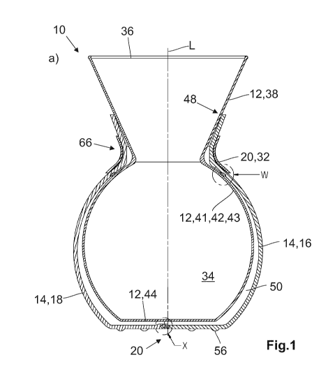
In Figure la), an embodiment of a double-walled vessel according
to the invention 10 is shown with reference to a sectional view.
The vessel 10 has an inner container 12 and an outer container
14. In the shown embodiment, the inner container 12 is made from
glass, while the outer container 14 is made from plastic. In the
shown embodiment, the outer container 14 comprises a first shell
16 and a second shell 18 that are detachably interconnectable.
For this purpose, the double-walled vessel 10 has a fixing device
that comprises a latching connection 22. As can be seen
particularly from Figure lb), the first shell 16 has a projection
24 that engages in a correspondingly shaped recess 26 of the
20 second shell 18. In addition, the projection 24 has a raised
section 28 that engages in a hole 30 or groove of the recess 26,
whereby a positive-locking connection is produced.
The fixing device 20 further comprises an elastic band 32 that
wraps around the first and second shells 16, 18 in the connected
state of these two shells and can be fastened to these shells,
which will be discussed in more detail below.
The inner container 12 encloses a cavity 34 that defines a
longitudinal axis L and in which a potable liquid, for example,
CA 03022757 2018-10-31
12
coffee or tea, can be put into the cavity 34 and can be poured
out of this cavity again via an opening 36. The inner container
12 has, starting from the opening 36 and viewed along the
longitudinal axis L, a tapering section 38 that has a conical
shape in the shown embodiment. The tapering section 38 forms, in
the area of the opening 36, a spout 40 with which the potable
liquid can be transferred in a controlled way, for example, into
a cup (see Figure 2b)). The tapering section can also be used for
holding a coffee filter, so that the coffee can be prepared
directly with the double-walled vessel.
An expanding section 42 that is convexly curved and thus forms a
convexly curved section 41 connects to the tapering section 38.
Due to the convex curvature, a section 43 that is inclined with
respect to the longitudinal axis L is formed. Starting from a
certain point, the diameter of the expanding section 42 no longer
increases, but instead decreases again and transitions into a
flat base area 44, so that the inner container 12 also has an
approximately spherical section or spherical segment shaped
section next to the conical section. On the outer surface, the
inner container 12 forms, on the expanding section 42, a support
surface 46 (see Figure 1c)), on which the outer container 14 is
supported in the connected state. The inner container 12 also
forms, on its tapering section 38, a contact surface 48, on which
the outer container 14 contacts the inner container 12 in the
connected state. Here, the contact surface 48 and the support
surface 46 are arranged and oriented so that they clearly define
the position of the outer container 14 relative to the inner
container 12. When the outer container 14 encloses the inner
CA 03022757 2018-10-31
13
container 12 in the connected state, it can no longer move
relative to the inner container 12.
The shape of the outer container 14 approximately corresponds to
the shape of the inner container 12, so that the outer container
14 also has a conical section and a spherical section.
As emerges, in particular, from Figure la), an intermediate space
50 is formed between the inner and the outer container 12, 14,
when the outer container 14 encloses the inner container 12 as
shown in the closed state. From Figure 1c) it emerges that the
outer container 14 has a first seal 52 with which the outer
container 14 is in contact with the inner container 12 in the
area of the support surface 46. From Figure lb) it can be seen
that the outer container 14 further has a second seal 54 with
which the first shell 16 is sealed relative to the second shell
18. The second seal 54 projects over its entire length into a
plane that runs along the longitudinal axis L. In this way, it is
achieved that the air that is located in the part of the
intermediate space 50 sealed by the first seal 52 cannot escape
into the surroundings, as long as the first seal 52 is completely
functional. In this way, an especially effective insulation of
the first container 12 is achieved, so that the temperature of
the drink stored in the cavity 34 of the first container 12
changes only very slowly to the temperature of the surroundings.
On the bottom, the outer container 14 has a number of feet 56
with which the vessel 10 can be placed securely on a support
base.
CA 03022757 2018-10-31
14
In Figure 2a), a side view of the embodiment of the double-walled
vessel 10 shown in Figure 1 is shown. It can be seen that the
first shell 16 has a first pin 58 and the second shell 18 has a
second pin 60, wherein the first pin 58 has a first pin section
62 that extends essentially vertically with respect to the
representation selected in Figure 2a) and the second pin 60 has a
second pin section 64 that extends essentially horizontally. The
pins 58, 60 are arranged in the area in which the conical section
transitions into the spherical section, where both the inner
container 12 and also the outer container 14 form a neck 66.
From Figures 2b) and 2c) it can be seen that the second seal 54
is not only on the base, as shown in Figure lb), but also runs
vertically, so that the second seal 54 runs along the entire
contact surface on which the first shell 16 is in contact with
the second shell 18 in the connected state.
In Figure 3b) it can be seen that the elastic band 32 has, at
each of its two ends, two cut-outs 68 that can be slipped onto
the first pin 58 and the second pin 60. The cut-outs 68 are
shaped so that they correspond to the orientations of the first
pin section 62 and the second pin section 64 shown in Figure 2a).
In this way it is achieved that the elastic band 32 can be
slipped onto the two pins 62, 64 in only one orientation.
For connecting the first shell 16 to the second shell 18, these
are positioned around the first container 12 and moved relative
to each other until the projection 24 of the first shell 16
engages in a positive-locking connection in the recess 26 of the
second shell 18. The latching connection 22 can be constructed so
CA 03022757 2018-10-31
that the user receives clear feedback when the two shells 16, 18
are connected to each other. Then the elastic band 32 is placed
with one end on the two pins 58, 60, wrapped once around the two
shells and then pushed with the other end on the two pins 58, 60.
5 In this way, the two shells 16, 18 are connected to each other
not only by means of their latching connection 22, but also by
means of the elastic band 32.
As already explained above, the pins 58, 60 are arranged in the
10 area, in which the conical section transitions into the spherical
area. As already mentioned, the inner container 12 and the outer
container 14 form the neck 66 in this area. Due to the
arrangement of the pins 58, 60, the elastic band 32 runs along
the neck 66 of the outer container 14, whereby slippage of the
15 elastic band 32 is prevented. Slippage is also avoided in that
the elastic band 32 must be put in tension when wrapping around
the two shells 16, 18, because the distance between the cut-outs
68 is smaller than the circumference of the neck 66.
To detach the outer container 14 from the inner container 12, the
elastic band 32 is removed from the pins 58, 60 and consequently
from the outer container 14 and the two shells 16, 18 are pulled
apart from each other. The detachment is provided so that, in
particular, the vessel 10 can be cleaned.
CA 03022757 2018-10-31
16
List of reference symbols
Vessel
12 Inner container
5 14 Outer container
16 First shell
18 Second shell
Fixing device
10 22 Latching connection
24 Projection
26 Recess
28 Raised section
15 30 Hole
32 Elastic band
34 Cavity
36 Opening
38 Tapering section
40 Spout
41 Convexly curved section
42 Expanding section
43 Inclined section
44 Base area
46 Support surface
48 Contact surface
50 Intermediate space
52 First seal
CA 03022757 2018-10-31
17
54 Second seal
56 Feet
58 First pin
60 Second pin
62 First pin section
64 Second pin section
66 Neck
68 Cut-out
L Longitudinal axis