Note: Descriptions are shown in the official language in which they were submitted.
CA 03023151 2018-11-02
WO 2017/198283 1 PCT/EP2016/002196
STIMULATING DEVICE
FIELD OF THE INVENTION
[0001] The invention relates to a stimulating device, particularly for
stimulating the
diaphragm, the use of such a device and methods of treating hypoventilation
and
respiratory depression. More particularly, the present invention relates to a
device for
stimulating the diaphragm to enhance pulmonary function, particularly by
biomechanical
muscle stimulation. A belt is provided containing at least two vibration
modules, which are
externally applied to an abdominal region of a user to stimulate the
diaphragm.
BACKGROUND
[0002] it is known that biomechanical muscle stimulation in various diseases
leads to the
improvement of the condition of the patient. The main application of
biomechanical
muscle stimulation is in the medical field, in sports and in cosmetics. In
particular, in the
medical field it has been found that a rapid and sustained improvement of
physical
mobility can be achieved using biomechanical stimulation for specific
diseases, in
particular for chronic pain, certain types of periphery paralysis, arterial
and peripheral
circulatory disorders, muscle metabolism disorders, muscle atrophy, muscle
dystrophy and
in various forms of arthritis.
[0003] DE 10 2004 009 452 B4 for example, discloses a device for stimulation
of the heart
muscle, which particularly promotes the conservation of the type Ha muscle
fibers. Here,
the device comprises a pulse generator unit for generating and sending out an
electrical
stimulation pulse. The unit can be controlled by a control unit. A
disadvantage of the
Date Recue/Date Received 2022-03-07
CA 03023151 2018-11-02
2
WO 2017/198283 PCT/EP2016/002196
device is that it is acting solely on the heart muscle and thus its use is
restricted. The
hardware of the device is solely restricted to the specific application.
[0004] Furthermore, DE 102 41 340 B4 describes a complex device for
biomechanical
.. muscle stimulation for use in rehabilitation, regeneration. A horizontal
tread plate is fixed
to a vibration unit, where the tread plate swings horizontally with an
amplitude of
preferably 4 to 5 mm. The user by means of handles, straps or ropes achieves
the desired
body tension. A disadvantage of the disclosed apparatus is that the vibrations
or
oscillations affect the whole body and cannot be applied locally to specific
muscles o
0 groups of muscles. Furthermore, the device is very large and cannot be
used on the move.
The stimulation of the muscles is exclusively achieved by active work
performed by the
user, which is not always possible to do. The device may be difficult or
impossible to be
used by the elderly.
[0005] DE 201 16 277 Ul discloses a device for biomechanical stimulation, with
the aid of
which a massage therapist can induce vibrations directly on certain areas of
the body of a
patient. The device comprises a vibration generator with a mechanical drive
unit for the
generation of oscillatory motions. The device is very large and heavy and
cannot be used
on the move. In addition, it is required to be operated by a trained
professional.
[0006] Conditions relating to chronic lung disease and respiratory depression
are
staggering in the developed and developing nations alike. As an example, in
the U.S. alone
Chronic Obstructive Pulmonary Disease (COPD) is the third leading cause of
death with
over 11 million individuals diagnosed with the condition. Conditions like
asthma affect
over 17 million in the U.S., including 5 million children. Examples of lung
depression
include sleep apnea, opioid use, pneumonia, interstitial lung disease, sleep
apnea,
congestive heart failure and psychogenic causes such as anxiety or PTSD. All
of these
conditions have varying pharmaceutical interventions providing varying
effectiveness,
with accompanying side effects.
[0007] Attempts have been made to remedy respiratory depression to relieve
ailments such
as COPD, sleep apnea and respiratory depression of various origin by external
stimulation,
however these attempts have not been ideal, successful or convenient to a
user.
CA 03023151 2018-11-02
3
WO 2017/198283 PCT/EP2016/002196
[0008] For instance, DE 298 12 986 U 1 discloses a respiratory stimulation
device
combining an alternating magnetic field effect with mechanical vibration for
mechanical
stimulation of abdominal and flank breathing. The device consists of a belt
with four
electrically driven motors and associated mechanical eccentrics. The motor is
placed
directly into a bulged plastic casing that generates vibrations in all
directions and thus the
whole unit vibrates Hence, vibrations cannot be controlled and there is no
damping of the
vibrations in any direction. A disadvantage of the devices described in the
prior art is that
the muscular stimulation is associated with not inconsiderable pain and the
user must
remain in a particular body position. In addition, electro-stimulation is
applied, which can
induce pain and needs to be in direct contact with skin. No data has
demonstrated
effectiveness, and it is questionable whether it is functional due to the
complicated motor-
magnet construction.
[0009] DE 202010018159 Ul discloses a respiratory stimulation belt comprising
an
integrated sensor unit and at least two vibration generators integrated a
housing and in a
tubular flexible structure. Due to the insertion of the housing of the
vibration generators in
the belt the vibration generators generate vibrations in all directions and
cannot be
controlled. The vibrations have a frequency of 6 to 12 Hz. There is no
indication of
frequency, amplitude or time required before effects, if any, are observed.
[0010] DE 10 2010 022 603 Al discloses a respiratory stimulation belt wherein
a flywheel
is magnetized or magnetized elements are incorporated into the flywheel to
enhance a
magnetic field generated by the motor and magnetic elements. The flywheel is
magnetized
by a disc magnet, part magnetic or bar magnet and the magneto-mechanical
vibrations
cause their effects via magnetic waves. Further, the magneto-mechanic
vibration unit can
be combined with an inductive transformation element causing electrical
stimulation
currents to muscles.
[0011] WO 01/19316 A2 discloses a digitally controlled vibratory therapy
apparatus
comprising one electromechanical vibrator and digital control means for
employing
cycloid vibrations. The digital control means utilizes linear time integrated
frequency
control and a small amplitude vibration without being further specific.
CA 03023151 2018-11-02
4
WO 2017/198283 PCT/EP2016/002196
SUMMARY OF THE INVENTION
[0012] Generally, as people age, their respiratory muscles weaken (the
diaphragm muscle
in particular), the lungs become more stiff and less elastic,
cardiorespiratory capacity is
reduced as well as mobility, making daily activity difficult and also reducing
sleep quality.
By 75 years of age, the vital capacity of the lungs is 50% less than younger
persons. In
other words, as people age, the lungs are functioning less efficiently and the
amount of
vital oxygen that is inhaled is reduced, which is essential for our brains,
heart and other
organs to function optimally. Also as people age, the correct breathing
pattern deteriorates
to the shallow, rapid chest breathing method, which has the negative effect of
using more
energy and activating stress within the body, as well as causing people to
inhale less air or
oxygen. This causes the wide experienced effects seen by many older persons
such as
anxiety, poor sleep, lack of mobility and even depression. The stress aspect
will also be
targeted towards additional age groups that suffer high stress or anxiety, as
well as those
having sleeping problems.
[0013] The present invention has the object to provide for an improved
stimulation device,
particularly for stimulating the diaphragm, the use of such a device and an
improved
method of treating hypoventilation and respiratory depression.
[0014] The stimulation device according to the invention comprises: a belt
containing at
least two vibration modules, wherein each of the at least two vibration
modules comprises:
a pod with a casing and a vibration pad arranged within the casing, and a
vibration motor
with a flywheel within the housing, a control panel operating said vibration
motors of the
at least two vibration modules; wherein the vibration motors are mounted to
the vibration
pad via at least one elastic motor housing.
[0014] The invention also comprises the use of a such device for treating
hypoventilation
and respiratory depression and a method of treating hypoventilation and
respiratory
depression by fastening the belt to the abdomen of a user and operating the
belt, wherein
the at least two vibration modules are externally applied to an abdominal
region of a user
to stimulate the diaphragm, to enhance pulmonary function.
=
CA 03023151 2018-11-02
WO 2017/198283 PCT/EP2016/002196
[0015] The elastic motor housing of the stimulation device provides for
elastic support of
the vibration motor relative to the belt and housing of the motor such that
generated
vibrations are mainly directed to the user and thus the energy impacting a
user is used more
efficiently compared to the devices known from the state of the art. With the
directed
5 .. vibrations due to elastic mount/suspension the vibration pad vibrates and
the impulse has
more degrees of freedom and provides for a better impact on diaphragm. The
device and
the method of the present invention enhance pulmonary function by stimulating
the
diaphragm.
[0016] The present invention alleviates symptoms related to hypoventilation
and shallow
breathing from various causes of lung disease and respiratory depression by
averting
pharmaceutical intervention and delivering relatively immediate results in
enhancing and
optimizing breathing ability. This results in increased blood oxygen levels,
reduced heart
and breathing rates and improved quality of life. The present invention is
easy to use,
overcomes the difficulties of use of the prior art, and has no observed
negative side effects.
The device of the present invention is more efficient than the prior art,
i.e., within 2 mins
the diaphragm is activated, and effects on 100% of individuals tested have
been observed.
[0017] The device and method according to the present invention can stimulate
the
diaphragm to enhance pulmonary function, and subsequently the parasympathetic
nervous
system to enhance relaxation, reduce the heart and breathing rates and improve
sleep
quality and even pain. For example, a program of the device may be used for
falling
asleep, where the number of revolutions of the motor is reduced. This however
can even
increase the positive effects on the user. The device contains a belt with at
least two
removable engaged vibration modules, which are provided to make contact with a
user to
engage the diaphragm of a user
[0018] Generally, the device of the present invention applies a biomechanical
vibration to
the human body through the contact of the vibration modules via the pods and
vibration
pads with the human body. The belt according to the present invention consists
of at least
two vibration modules, each housing a vibrating motor. The vibration modules
are engaged
with a strap, creating a belt, for contacting the abdomen of a user to
stimulate the
diaphragm. The motors are controlled by an electronic circuit. The electronic
circuit is
CA 03023151 2018-11-02
6
WO 2017/198283 PCT/EP2016/002196
controlled by a control panel, which may be powered by a battery that is
optionally
rechargeable. The control panel controls the voltage and time that the motors
run for.
[0019] The belt may be worn by a user any time during the day or night. The
belt of the
present invention may be worn only for the amount of time that the user wishes
for the
diaphragm to be stimulated, or it may be worn for an extended period of time
and the
vibration motors activated intermittently throughout the extended period of
time. The belt
of the present invention may be used in any position by a user, for instance
sitting,
standing, or in a supine position. The belt may be worn and used while working
in an
office, sitting at a computer or when engaging in manual labor. The vibrations
õtrain" the
diaphragm so that its ability to function or contract on its own increases and
after the use in
morning or evening should keep working for several hours. Minimum use time is
10 min
and upto 30-60 mm. Moreover, the diaphragm recognizes the vibrations
increasingly faster
with repeated use that it commences to work quicker with each use of the belt.
[0020] In an embodiment of the invention the belt comprises three vibrating
modules that
are arranged equidistant or in varying distance to allow for an optimal
stimulation effect of
the diaphragm for deep breathing movement of the stomach, i.e. the pods and
vibration
pads with the motors continue to vibrate optimally during the õexpansion"
phase during
.. inhalation.
[0021] In an embodiment of the present invention each of the vibration motors
of the
device is spaced away from the vibration pad via the motor housing. This
measure ensures
a free movement of the flywheel attached to the motor within the housing or
casing.
[0022] In an embodiment of the present invention in the device the motor
housing is
mounted to the vibration pad via a snap-fit connection. This measure provides
for a secure
coupling of the motor and the motor housing. Alternatively, suitable
attachment means
may be used and or additional attachment means, e.g. adhesives or mechanical
couplings.
[0023] In an embodiment in the device of the present invention each of the
motor housings
is at least partly designed in a complementary manner to the vibration motor
for holding
CA 03023151 2018-11-02
7
WO 2017/198283 PCT/EP2016/002196
and supporting the vibration motor. This measure provides for an easy assembly
of the
device and a secure support of the motor within the motor housing.
[0024] In an embodiment of the present invention the belt of the device
comprises a strap
having at least one a belt fastening attachment. The belt may be flexible.
This measure
provides for an easy adjustment of the belt to the user, specifically to the
abdomen of the
user. The belt fastening attachment may be of any suitable fastening means.
[0025] In an embodiment of the present invention the casing comprises a main
casing and
a back casing wherein the vibration pad is arranged within the back casing
and/or the main
casing is provided with a front panel. With this measure the vibrations are
directed to a
user more efficiently. Specifically with an elastic vibration pad and the
elastic motor
housing the vibrations impacting on the casing are dampened and the vibration
pad is
supported resiliently with respect to the casing.
[0026] In an embodiment of the present invention the main casing and/or the
back casing
of the device comprise at least one attachment means for engagement with and
through the
strap and engagement with the other of the back casing or main easing. This
measure
provides for a suitable and safe connection between casing and strap and
ensures that the
vibration pads are kept in position.
[0027] In an embodiment of the present invention the control panel operates
said vibration
motors with an amplitude from around 0.3G to 1.0G and frequency ranging from
16 Hz to
45 Hz complementary to a voltage 0.6V to 1.3V. Preferably the control panel
operates said
vibration motors with an amplitude of around 0.4G at a frequency of 30 Hz
(0.8V) to an
amplitude of 0.62G at a frequency 37 Hz (1.0V). The exact optimal frequency
and
amplitude is also person dependent, i.e. weight, age and general sensitivity.
With these
operation conditions optimal effects are achieved and quantified as clear
changes in
breathing pattern to deep, slow rhythmic diaphragm breathing and quantified as
reduction
in breathing rate of 20% or more.
[0028] In an embodiment of the present invention the belt is flexible and/or
adjustable to a
wearer's anatomy. Hence, the length of the belt can easily be adapted to the
users and one
belt can be adapted to different users.
CA 03023151 2018-11-02
WO 2017/198283 8 PCT/EP2016/002196
[0029] In an embodiment of the present invention the at least one of the
flywheels is
dimensioned of around 12 mm diameter and 8 mm thickness. This measure provides
for
efficient vibrations.
[0030] In an embodiment of the present invention the at least one of the
flywheels has a
weight of 7-8 grams and/or is spaced 1-5 mm from the end of the motor. This
measures my
even more improve the efficiency of the device and the impact of the vibrating
impulses.
This weight and arrangement is based on several test results (compare below).
[0031] In an embodiment of the present invention the device may further
comprise a
display for displaying and monitoring vital functions, wherein the display of
vital functions
is integrated via an interface and/or the interface supports the exchange of
information with
an external device. This measure can improve the functionality of the device.
[0032] In a further embodiment the invention provides for a method of treating
respiratory
depression by engaging a belt device to the abdomen of a user, the belt device
comprising:
a) a strap having a belt fastening attachment; b.) at least two vibration
motors engaged with
said strap; c) said motor comprising a flywheel of 12 mm diameter, 8 mm
thickness and 7-
8 grams; d) a control panel operating said at least two vibration motors;
wherein said
vibration motors have amplitude from 0.3G to 1.0G and frequency ranging from
16 Hz to
45 Hz. In an embodiment the at least two vibration modules are externally
applied to an
abdominal region of a user to stimulate the diaphragm, to enhance pulmonary
function.
[0033] In an embodiment, the device of the present invention contains a belt,
wherein the
belt is adjustable in size to accommodate for variations in the size of a
user. The belt
contains at least two removable vibration modules, each module containing a
vibration
motor controlled by a control panel device. The belt of the present invention
is provided to
contact the abdominal region of a user under the rib cage to stimulate the
diaphragm.
[0034] The vibrating motor of the present invention may be effective at
varying voltage,
amplitude and frequency. An approximate effective range of the amplitude is
from about
CA 03023151 2018-11-02
9
WO 2017/198283 PCT/EP2016/002196
0.3G to about 1.0G, or a voltage from about 0.6V to 1.3V. An approximate
effective range
of the frequency is from about 16Hz to about 45 Hz.
[0035] In an embodiment of the invention, the device can be used to deepen
abdominal or
flank breathing. Abdominal breathing, also called diaphragmatic breathing, is
a normal,
easy breathing form. The diaphragm is the main breathing muscle and is located
between
the chest and the abdominal cavities. Abdominal breathing occurs by a
contraction of the
diaphragm, whereby the negative pressure in the pleural space is growing.
Following this
negative pressure, the lung extends and air gets sucked in. Exhalation in this
breathing
technique occurs by relaxation of the diaphragm, whereby the lung due to its
own elastic
properties contracts and pushes the air out. Consciously, exhalation can be
supported by
contracting the abdominal muscles.
[0036] The device may be used for increasing the activity of the diaphragm.
With the
contribution of mechanical vibrations, the muscle of the diaphragm gets
stimulated and
subsequently can contribute to a better expansion of the lungs. A further
benefit of using
the device of the present invention is the activation of the parasympathetic
nervous system,
which subsequently reduces heart and breathing rates, increases muscle
relaxation, relieves
tension, pain in lower torso, abdominal contractions and improves sleep
quality. In
addition, the use of the device of the present invention helps with sleeping
disorders such
as insomnia. Yet another benefit of the device of the present invention is the
assistance in
weaning an individual from the use of mechanical ventilation.
BRIEF DESCRIPTION OF THE DRAWINGS
[0037] FIG. 1 illustrates a front view of an adjustable belt, in a linear open
position, having
at least two vibration modules and associated control panel.
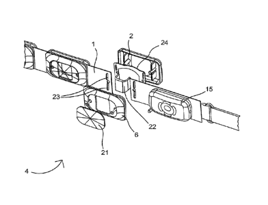
[0038] FIG. 2 illustrates an exploded view of a pod component of a vibration
module.
[0039] FIG. 3 illustrates a view of the user contact side of a belt having at
least two
vibration modules and associated control panel.
[0040] FIG. 4 illustrates a vibration motor.
[0042] FIG. 5 illustrates a front perspective view of the control panel.
CA 03023151 2018-11-02
wo 2017/198283 10 PCT/EP2016/002196
[0042] FIG. 6 illustrates a back perspective view of the control panel.
[0043] FIG. 7 illustrates an exploded view of the control panel.
[0045] Fig 8a illustrates a back perspective view of a vibration module.
[0044] Fig 8b illustrates a sectional side view of the vibration module 12 of
Fig. 8a.
DETAILED DESCRIPTION OF THE INVENTION
[0045] While the present disclosure may be susceptible to embodiments in
different forms,
the drawings show, and herein will be described in detail, embodiments with
the
understanding that the present description is to be considered an
exemplification of the
principles of the disclosure and is not intended to be exhaustive or to limit
the disclosure to
the details of construction and the arrangements of the components set forth
in the
following description or illustrated in the drawings.
[0046] Generally, the device of the present invention applies a mechanical
vibration to the
human body through the contact of vibration pads of a respective pod
comprising vibration
motors. The present invention consists of at least two vibration modules, each
housing a
vibrating motor. The vibration modules are engaged with a strap, creating a
belt, for
contacting the abdomen of a user to stimulate the diaphragm. The motors are
controlled by
an electronic circuit. The electronic circuit is controlled by a control
panel, which may be
powered by a battery that is optionally rechargeable. The control panel
controls the voltage
and time that the motors run for. The belt may be worn by a user any time
during the day
or night. The belt of the present invention may be worn only for the amount of
time that
the user wishes for the diaphragm to be stimulated, or it may be worn for an
extended
period of time and the vibration motors activated intermittently throughout
the extended
period of time. The belt of the present invention may be used in any position
by a user, for
instance sitting, standing, or in a supine position. The belt may be worn
while working in
an office, sitting at a computer or when engaging in manual labor.
[0047] FIG. 1 illustrates the front view of a length-adjustable belt 10 of the
present
invention in an open position, comprising three vibration modules. More
particularly, the
belt 10 comprises a first vibration module 5, a second vibration module 7 and
a third
CA 03023151 2018-11-02
wo 2017/198283 11 PCT/EP2016/002196
vibration module 9. Each vibration module comprises a casing 6 and a pod 4
containing a
vibration motor. The belt 10, further depicts a strap 1 between the vibration
modules 5, 7
and 9.Further, a control panel 15 is mounted to the strap 1 in any suitable
manner, for
example via clamp 8. The vibration modules 5, 7 and 9 are mounted to the strap
1 of the
belt 10 equidistantly. When attached to a human being this arrangement allows
for the
optimal stimulation effect of the diaphragm for deep breathing movement of the
stomach,
i.e., the belt 10, i.e. vibration pads of the vibration modules 5, 7 and 9
(pods 4) with the
motors continue to vibrate optimally during the õexpansion" phase during
inhalation.
[0048] The strap 1 of belt 10 may be constructed of a variety of suitable
materials,
including lycra, any material containing spandex, neoprene, elastic, cotton,
nylon webbing,
StretchBandsTM, silicone, ethylene propylene diene monomer (M-class) rubber,
urethane,
Chloroprene, Hypalon, natural rubber, leather, cloth, plastics and the like.
In an
embodiment, the strap 1 is stretchable and made of materials such as including
lycra, any
material containing spandex, neoprene, elastic, nylon webbing, StretchBandsTM,
silicone,
ethylene propylene diene monomer (M-class) rubber, urethane, Chloroprene,
Hypalon or
natural rubber. In yet another embodiment, strap 1 is made of a combination of
neoprene,
elastic and nylon webbing. Strap 1 may be of varying lengths and widths
suitable for the
size of the respective user. Strap 1 may be constructed of an inner strap,
closest to the
abdomen of a user, and an outer strap away from a user. Between the inner
strap and outer
strap are a path of the wires leading from a control panel to the motors.
Alternatively, the
path of the wires may be integrated in the strap.
[0049] Belt 10 further comprises a belt fastening attachment 2, 3 for closure
around a user.
The belt fastening attachment 2, 3 may be selected from a variety of off the
shelf buckles
such as quick-release clips, simple buckles, adjuster buckles, belt buckles
and the like. In
other embodiments, the belt securing attachment 2, 3 may comprise snaps,
clips, zippers,
buttons, clasps, clips, knots, ties, Velcro, pins, hooks or any other
fastening means known
in the art.
[0050] Vibration modules 5, 7 and 9 each contain a removable pod 4, which
contains a
vibration motor. Pod 4 is advantageously removable for repair or exchange of
the pod or
vibration motor. In an embodiment, the motor sits in a plastic housing that
clicks into
CA 03023151 2018-11-02
wo 2017/198283 12 PCT/EP2016/002196
place, and the outer casing of the removable pod(s) 4 is screwed over the
complete casing
6. The pod can also be glued to casing 6. Said pod 4 may be made by injection
moulding of
materials such as plastic, metal, silicone, synthetic fabric and the like. The
dimension of
the pod may vary. Smaller pods may be used for smaller belts and larger pods
may be used
for larger belts. In an embodiment, the pods may be about 6-8 cm in width;
about 8-9 cm in
Length; and about 2.5-3.5 cm in depth depending on the size of the motor to be
housed.
[0051] Relating to Fig. 2, the exploded view of pod 4 illustrates a front
panel 21, which
covers the pod. The front panel 21 may be made of ABS plastic and made by
injection
molding. The front panel 21 may be made of any metal or other suitable
material. The front
panel 21 may be of any color and may be imprinted or embossed with a logo or
design.
The casing 6 forms a structural cabinet feature that clamps the strap into
position and
guides the wiring. The belt has slits 23 for engaging the casing 6 to secure
to the belt. The
casing 6, may also be made by injection molding of ABS plastic. The casing 6
may also be
made of metal or any other suitable material. The pod 4 also comprises a back
casing 26
with a motor housing 22. The motor housing 22 receives and houses a vibration
motor 20
and is mounted to a vibration pad 24. The motor housing 22 isolates the motor
from main
casing 6. In an embodiment, the motor housing 22 may be made of ABS plastic by
injection moulding, or may be made of any other suitable material. In an
embodiment each
of the motor housings 22 is made of an elastic material, e.g. silicone. The
motor housings
22 are designed at least partly complementary to the outer surface of the
motor 20 (comp.
Fig. 4 and 8a, b) to receive and hold the motor 20 when the pod 4 is mounted
or assembled.
The vibration pad 24 is used to transmit the vibrations from the motor to the
user's body.
The vibration pad 24 incorporates damping features, such as a sponge, and
isolates the
vibration motor from main casing 6. The vibration pad may be made of a
silicone, i.e.
Rubber, TPE/TPU or PVC or any other suitable material. The back casing 26
forms a
structural cabinet to clamp the strap in position via slits 23 of strap 1 and
to guide wires.
For this purpose the back casing 26 comprises two extensions that extend
perpendicularly
to the back casing 26 for engagement with slits 23 of strap 1. The casing 6
comprises pins
or other suitable means also extending perpendicularly to the casing 6 for
counter
engagement with the extensions to hold the vibration modules 5, 7 or 9 or pod
4 securely
on the strap 1 in position. The back casing 26 may be made by injection
moulding of ABS
plastic, or may be made of metal or any other suitable material.
CA 03023151 2018-11-02
wo 2017/198283 13 PCT/EP2016/002196
[0052] Fig. 3 illustrates the posterior side of the casing 6 and the user
contact side of the
pod 4, whereby contact is made by vibration pads 12, 14 and 16 (24 in Fig. 2).
The
vibration pads 12, 14 and 16 (24) provide beneficial features, such as
transmitting the
vibration effects in a more focused and efficient marmer than plastic casing
due to the
elastic support or mount of the motor 20 within the elastic motor housing 22.
The elastic
support of the motor 20 with respect to the casing 6 and back casing 26 allows
for directing
most of the generated vibrations to the user increasing the efficiency of the
stimulation
device. The silicone vibration pad is also quieter than plastic casing
construction and more
comfortable for a user.
[0053] Vibration motors used in the present invention may be off the shelf and
equivalent
to Precision Microdrives TM, Model 320-100, Uni-Vibe TM, 20mm Vibration Motor -
25mm Type. A variety of motors may be used, as generally illustrated in Fig.
4. The
vibration motor may generally include motor casing, washers, a NdFeB neodymium
permanent magnet, a motor shaft, a motor end cap, ball race bearings and an
eccentric
mass counter weight (the flywheel 28). Larger or smaller motors may be used in
the
present invention, but what is critical is that the frequency or amplitude or
voltage range is
achieved with any type of motor for the effect to be seen. It has been noted
with larger
motors, a user may experience discomfort, pain or abrasions. However, in the
present
invention, variations in performance were noted when similar motors were
tested with
variations of size and weight of the flywheel. The flywheel should be spaced 1-
5 mm from
the end of the motor in a preferred embodiment.
[0054] Surprising results were seen related to a small change in the flywheel
size/dimension and weight, which had a significant effect on stimulating the
diaphragm in
an effective manner. In addition, an optimal range of the frequency-amplitude
was
determined, outside of which effectiveness in stimulating the diaphragm
significantly
decreases. Therefore, the frequency- amplitude relationship is very critical
to cause
activation of the diaphragm. Activation of the diaphragm can be measured as a
change in
breathing pattern, i.e., shallow breathing versus slower deep belly breathing.
This can be
quantified by slower breathing (rate/min) and also heart rate.
CA 03023151 2018-11-02
wo 2017/198283 14 PCT/EP2016/002196
The flywheel was of 12 mm diameter, 8 mm thickness and 7-8g. The motor is
Precision
Microdrives TM, Model 320-100.
Table:
Effects on diaphragm quantified as below:
+++ is strong activation of deep belly (diaphragm) breathing; the breathing
rate is deeper
and slower as measured by breaths per minute (reduction greater than 20% of
normal
previous breathing)
+ is only slight effect on diaphragm breathing i.e., a 10% or less reduction
of breathing rate
- No effect on diaphragm activation or breathing rate
Voltage Amplitude Frequency Effect on
diaphragm
1.2 V 0.95G 43 Hz +++
1.0 V 0.62G 37 Hz +++
08V 0.4G 30 Hz +++
Precision Microdrives TM, Model 2 (320-105 standard). This has exactly the
same motor
as above, but different flywheel (18 mm diameter x 6 mm thickness, but is only
a half
circle, i.e., not complete).
Voltage Amplitude Frequency Effect
1.2 V 1.0 G 45 Hz
1.0 V 08G 35 Hz
0.8V 0.5G 28 Hz
Model 3. Same motor but flywheel slightly different (10 mm diameter, 3.5 mm
thickness)
CA 03023151 2018-11-02
wo 2017/198283 15 PCT/EP2016/002196
Voltage Amplitude Frequency Effect
1.2V 0.8G 55 Hz
1 0 V 0,54G 45 Hz
0.8V 0.34G 37 Hz
Effects on lung function were notable within the range from 0.3G at 20 Hz to
1.00 at 45
Hz. Optimal effects were observed in the range from 0.8V (30 Hz at 0.4G) to
1.0V (37 Hz
at 0.62G). Optimal effects are quantified as clear changes in breathing pot-
tern to deep,
slow rhythmic diaphragm breathing and quantified as reduction in breathing
rate of 20% or
more. The amplitude was measured using a closed-loop control (accelerometer)
and
accurate motor speed measurement device. An MMA 7361 triple axis accelerometer
from
Freescale was used and mounted on a PCB with several external components. The
vibration motor and accelerometer were mounted together. These were then
mounted with
a 100g mass (sled). This target mass has a direct influence on the measured
vibration
= amplitude and helps to standardize the measurements. This was done as
described by
Precision Microdrives of UK.
[0055] The device of the present invention comprises a single control panel
PCBA, which
includes a number of TACT switches and LED's. The control panel may be used to
control
the speed of the motors by varying the voltage supplied to the motors. The
control panel
may also control the time the motors run for and have pre-programmed functions
that
control the time for different motor speeds. Fig. I additionally, illustrates
a control panel
15, removably engaged with strap 1, for convenient storage via clamp 8.
Control panel 15
is a handheld device, which can work independently from the power grid using a
grid-
independent power supply, such as a battery. Generally, the control panel 15
may be made
of any suitable plastic or metal known in the art. Control panel 15 may be
fixedly or
removably secured to strap 1 by any means known in the art.
[0056] Fig. 5 illustrates a front perspective of the control panel 15, having
a front control
panel casing 40. Also illustrated, a wire port 41 connects a circuit board in
the control
panel 15 to the motors. Power control pad 42 turns the control panel 15 on or
off. Program
CA 03023151 2018-11-02
wo 2017/198283 16 PCT/EP2016/002196
1 control pad 43 is to select a pre-programmed schedule of voltage and time by
which the
vibrating motors will operate. Examples of such programs are provided below.
Program 2
control pad 44 is to select an alternate pre-programmed schedule of voltage
and time by
which the vibrating motors will operate. Examples of such programs are
provided below.
A timing control pad 45 may provide a step-wise increase of the time the
vibrating motor
will operate. A timing button may be programmed to increase or decrease in any
increment
of time, such as seconds, minutes, hours and the like each time it is
selected. Timing
Magnitude Indicators 46 is a light feature to indicate the increase or
decrease in increments
of time. Speed control pad 47 is selected to increment Voltage each time it is
selected. The
increment in Voltage may either be an increase or decrease, the magnitude of
which is
indicated by the lighting on Speed Magnitude Indicators 48. Varying control
features may
be incorporated into a control panel for the present invention. LED readouts
of which
program is selected, the speed, timing and any other useful information for a
user may be
provided. Additional control buttons may be added, which may be specific to
each motor,
for instance to turn the power on an off for each motor independent of the
others. Other
controls and selection buttons may be added for independent control of the
speed, voltage,
amplitude, frequency and time of Operation of each motor independent of the
others.
Those skilled in the art will recognize that a variety of controls may be
incorporated in the
control panel to enhance the user experience for convenience and/or maximum
health
benefit. The buttons of the present invention may be made of any suitable
material known
in the art, and may include silicone and rubber.
[0057] Fig. 6 illustrates a back perspective view of control panel 15,
providing a back
control panel casing 50 and view of charging port 51 for recharging a
rechargeable battery
in the control panel 15. Fig. 6 illustrates charging port 51 as a micro USB
port, however
any suitable charger and port used in the art may be used. Fig. 6 also
indicates four screws
52, 53, 54, 55 by which the control panel is secured from the front panel to a
back panel
56.
[0058] Fig. 7 is an exploded view of control panel 15, having front control
panel casing 40
comprising perforations 61, 62, 63, 64, 65 for receiving control pads 42, 43,
44, 45, 47 (not
fully shown). Control pads 42, 43, 44, 45, 47 engage with and operate an
electrical circuit
board 70. Circuit board 70 is programmed with multiple programs to control the
voltage,
CA 03023151 2018-11-02
wo 2017/198283 17 PCT/EP2016/002196
amplitude, frequency and times for which the vibrating motors will engage.
Examples of
such programs are below. The back of the circuit board 70, not depicted,
comprises wire
connections for the electrical circuit to route through the wire port 41 to
the positive and
negative inputs of the vibrating motors. Pegs 81, 82 are used to mount the
front control
panel casing 40 to the back control panel casing 50. Fig. 7 also depicts a
rechargeable
battery 85, encased and enclosed within the control panel 15 by the back
control panel
casing 50. Rechargeable battery 85 may be any of those used in the industry,
including but
not limited to lithium sulfur, sodium ion, thin film lithium, zinc bromide,
zinc cerium,
vanadium redox, sodium-sulfur, molten salt, silver-zinc, Quantum Battery or
any other
suitable rechargeable battery.
[0059] The control panel may be programmed with different variations in
voltage and time
to provide a user with varied options depending on their health needs.
Programs may start
the rotating motors for any length of time, but the best results have been
seen with at least
10 minutes of use. Motors may be programmed to pulsate or provide intermittent
stimulation of the diaphragm, of varying duration, throughout the day for a
user that wears
it throughout the day or night. Examples of programs selectable on the control
panel are as
follows:
Program 1
Voltage Time (mm)
1.0V 10
0.9 10
0.8 10
Program 2
Voltage Time (min)
1.0V 5
0.9 10
0.8 15
Program 3
Voltage Time (min)
CA 03023151 2018-11-02
wo 2017/198283 18
PCT/EP2016/002196
1.2V 2
1.0 10
0.9 10
0.8 10
Program 4
Voltage Time (min)
1.2V 5
1.0 5
0.9 10
0.8 10
Program 5
Voltage Time (min)
0.8 10
0.7 10
0.6 10
0.7 5
0.8 5
Program 6
Voltage Time (min)
0.9 10
0.8 10
0.7 10
0.6 10
0.8 5
Program 7
Voltage Time (min)
1.0 10
None 5
1.0 10
None 5
0.8 10
This cycle
repeats for 1
hr
CA 03023151 2018-11-02
WO 2017/198283 19 PCT/EP2016/002196
Program 8 - For Sleep Apnea Patients
Voltage Time (min)
1.0-1.2 10
0.9V 5
- 0.8V 5
Off 10
0.8 10-20
seconds
every 2-5
minutes
This cycle
repeats for 2-
3 hours
[0060] Clinical results indicating the effectiveness and health benefit of the
present
invention were obtained. In one trial, 68 COPD grade patients were tested.
These patients
used the device of the present invention three times per day, for 20 minutes,
and for 10
days. The results were as follows:
1. 62 patients reduced their breathing rate from 18 to 14 breaths/minute.
2. 62 patients improved their blood p02 from an average 92% to 97%.
3. 58 patients described their breathing as more comfortable.
18 patients received treatment with the device of the present invention for 2
weeks. Of
those patients, 14 could walk without shortness of breath and 11 could reduce
their
medication needs after the 2 week course of treatment.
[0061] A small study with 3 patients suffering from sleep apnea was able to
show that
when the patients stopped breathing, activation of the device of the present
invention (only
for a few seconds) caused the patients to immediately start breathing. The
sleep apnea
patients could subsequently continue to sleep without any disruption.
CA 03023151 2018-11-02
WO 2017/198283 20 PCT/EP2016/002196
[0062] In geriatric patients treated with the device of the present invention,
muscle
relaxation in regions of the legs, belly region and chest were clearly
observed, as well as a
more relaxed and slow breathing rhythm. This enabled the patients to feel
better and allow
physical movement
[0063] Other applications of the present invention may include patients
suffering from lung
cancer, lung surgery, cystic fibrosis, ADHS, cardiac intervention or infarct
or pneumonia
or ALS patients. Obese people may also benefit from the present invention
since they may
have a limited lung volume due to greater adipose tissue around the lungs,
which reduces
the bronchioles, limits lung capacity and increases the breathing rate,
leading to fess
oxygen intake. In addition, people with insomnia who have been treated with
the device of
the present invention have reported significantly longer and better quality
sleep and report
feeling refreshed the following day.
[0064] In yet another study, ten patients with COPD were treated with the
device of the
present invention for fifteen minutes. After a single use of the belt, the
lung volume of all
ten patients significantly increased as indicated in the following chart.
Lung Vital Capacity (cm3)
COPD Patients treated with Belt for 15 min
3000
2000 I
1000
I = 4.111 111 111 I I 1
0
g- c) ci) L. s- a) s- " a) s- 1-
a) 1-
5-, 0 5. CU <15 <1.) 5., LI)
5-, 5¨ CD
0 0 0 0 0 0 0 tt: 0 0
t1) 4C-'15 '-C7) t3.) < (1) < < < <
ca co
Patient Patient Patient Patient Patient Patient Patient Patient Patient
Patient
1 2 3 4 5 6 7 8 9 10
CA 03023151 2018-11-02
WO 2017/198283 21 PCT/EP2016/002196
[0065] Another patient who used the belt of the present invention, a self-
reported strong
smoker, had consistent coughing and wheezing prior to using the belt. The
patient reported
a cessation of coughing and wheezing for three days after a single use of the
belt for 15
minutes.
[0066] The device of the present invention may also be used for monitoring
specific vital
functions. A display of vital functions can be integrated via an appropriate
interface. An
embodiment of the device has at least one interface that supports the exchange
of
information. The information can be present in the form of physical units
(e.g., as electrical
voltage, current strength) or logical variables (data), whereas the exchange
can be analog
or digital. The interface includes data interfaces (interfaces for data
transmission in
general), general interfaces, machine interfaces (interfaces between physical
systems),
hardware interfaces (interfaces between physical systems of computer
technology),
network interfaces (interfaces between network components), software
interfaces
(interfaces between programs) and / or user interfaces (interfaces between man
and
machine). Preferred interfaces include radio or infrared interface or wired
interfaces (for
example USB). Using the interface, a secure and fast connection can be
established and
information exchanged. In addition, the device may be connected to other
devices for
monitoring vital functions, allowing a check of the safe and efficient
operation of the
device. It may also be preferred that the information (e.g. data) is saved on
a storage
medium or is transmitted from a computer based system - a transmitter ¨ to the
recipient
via a network-based transmission or a long distance data transmission. The
transmission
medium is preferably the telephone network, radio or light, whereby a rapid
and secure
transfer of information is possible. Advantageously, the device itself has a
memory that
can store the data, such as duration of use and rotation speed selected. The
device may
transfer the data to an external storage medium. The data can be
advantageously used for
the analysis of the application, thereby allowing optimization of the
application.
[0067] Fig 8a illustrates a perspective back view of a vibration pad 12 (14,
16) without
main casing 6 and back casing 26. Fig 8b illustrates a sectional side view of
the vibration
pad 12 of Fig. 8b. The vibration pad incorporates damping features, such as a
sponge, and
isolates the vibration motor from main casing 6. The vibration pad 12 is
designed to house
the motor 20 and comprises a rectangular outer surrounding with rounded edges
that is
CA 03023151 2018-11-02
WO 2017/198283 22 PCT/EP2016/002196
designed like a trough. On both sides of the vibration pad 12/24 flat side
extensions are
provided for mounting the vibration pad 12/24 to the strap 1 and the casing 6
as well as
back casing 26 (compare Fig. 2). For this purpose the extensions comprise each
two slits
91 and a hole (partly shown in Fig. 8a) that are designed complementary to the
extensions
.. of the back casing 26 as well as the mounting means of the main casing 6
for secure
engagement when the vibration module 5, 7, 9 is assembled.
[0068] On the inner surface of the trough of the vibration pad 12/24 two tabs
87 are
provided on both sides that extend approximately in parallel to one of the
slits 91. The tabs
87 are provided for secure engagement of the motor housing 22 with the
vibration pad
12/24. For this engagement the motor housing 22 comprises on both its lower
end sides
slits complementary to the tabs 87 for a snap fit connection when passing the
tabs 87.
Further, in some embodiments also suitable adhesives, e.g. silicone glue may
be added on
the mounting area to improve this connections. The motor housing 22 is further
designed
in a "u"-like shape, complementary to motor 20 for receiving and holding the
motor 20.
When the motor 20 is mounted via the motor housing 22 to the vibration pad
12/24 it is
kept at a distance to the inner.surface of the vibration pad 12/24 such that
the flywheel 28
can move within the casing 6 and back casing 26 freely without any contact to
the casing 6
and back casing 26 (compare Fig. 8b). Further, the motor 20 comprises two
connectors 95
extending from the end of the motor 20 opposite to the flywheel 28 for
electrical
connection with the control panel 15 via wires (not shown). The vibration pad
12 provides
beneficial features, such as transmitting the vibration effects in a more
focused and
efficient manner than plastic casing due to the elastic support or mount of
the motor 20
within the elastic motor housing 22. The elastic support of the motor 20 and
flywheel 28
.. with respect to the casing 6 and back casing 26 allows for directing most
of the generated
vibrations to the user thereby increasing the efficiency of the stimulation
device.
[0069] Although preferred embodiments of the disclosure are illustrated and
described in
connection with particular features, it will be apparent to those skilled in
the art of
vibration treatments and respiratory therapies that the present invention, or
variations
thereof, can be adapted for use for a wide variety of treatments for
individuals suffering
from respiratory depression due to various causes. Various features of the
disclosure have
been particularly shown and described in connection with illustrated
embodiments.
CA 03023151 2018-11-02
23
WO 2017/198283 PCT/EP2016/002196
However, it must be understood that the particular embodiments merely
illustrate and that
the invention is to be given its fullest interpretation within the terms of
the claims.