Note: Descriptions are shown in the official language in which they were submitted.
CA 03023442 2018-11-06
a
SOLENOID VALVE FOR CONTROLLING FLUID
TECHNICAL FIELD
[0001] The present disclosure relates to a fluid control solenoid valve for
controlling the flow of
a raw material gas when filling the raw material gas stored in a high-pressure
vessel into another
high-pressure vessel or supplying the raw material gas to a gas consumer unit.
BACKGROUND ART
[0002] Currently, in the case of a hydrogen fuel cell system, a fluid control
valve is provided in
a high-pressure vessel storing a raw material gas to control the flow of the
raw material gas when
the raw material gas is charged into the high-pressure vessel, and to control
the flow of the raw
material gas, when the raw material gas stored in the high-pressure vessel is
supplied to a gas
consumer unit.
[0003] The fluid control valve can precisely control the flow of a raw
material gas precisely
according to an electric signal, keep the pressure of fluid stored in a
pressure vessel to be
constant, and prevent explosion of a high-pressure vessel when a hydrogen fuel
cell vehicle
overturns or a fire occurs therein.
[0004] As disclosed in Korean Patent Publication No. 10-0002586 (published on
January 30,
2012), a conventional solenoid valve includes: a housing; a valve core
provided in the housing; a
plunger provided so as to be able to move forward and backward in the housing;
a packing
member mounted on the plunger; and a valve seat opened and closed by the
packing member,
wherein the plunger has a first accommodating portion for fluidly
accommodating the packing
1
CA 03023442 2018-11-06
member, wherein the first accommodating portion has an inclination portion so
that the packing
member is provided so as to be inclined and mounted, wherein the packing
member is disposed
in parallel with an end of the valve seat in a state where the valve seat is
closed, and the packing
member is arranged so as to be inclined at a predetermined angle with respect
to the valve seat,
in a state where the valve seat is opened.
[0005] However, since the conventional solenoid valve is equipped with the
packing member
for opening and closing the valve seat at the end portion of the plunger, a
process for mounting
the packing member on the plunger is required, thereby complicating the
manufacturing process.
Further, since the packing member is formed of a rubber material, the packing
member may tear
due to a certain high pressure.
[0006] As disclosed in Korean Patent Publication No. 10-0428184 (published on
April 09,
2004), a solenoid valve installed in another conventional compressed natural
gas storage tank
includes: a valve housing connected to a gas pipe; a coil wound in the valve
housing; and a
piston unit for selectively opening a gas pipe connected to the storage tank
while overcoming the
force of a valve spring as electric power is applied to the coil. In addition,
the piston unit
includes: an upper piston made of a steel material, which is coupled to one
end of the valve
spring installed in the valve housing and moves linearly in the valve housing
in a direction to
open or shut off the gas pipe connected to the storage tank; a lower piston
made of a steel
material, which is fitted into and coupled to the upper piston in the
longitudinal direction via a
coupling shaft formed at one end thereof and interlocked with the upper
piston; and an auxiliary
2
CA 03023442 2018-11-06
piston made of a steel material, which is coupled to a lower surface of the
lower piston so as to
be axially rotatable, and interlocked with the upper piston to open or close
the gas pipe
connected to the storage tank.
[0007] In other conventional solenoid valves, since the upper piston and the
lower piston are
connected to each other by the coupling shaft, there is a risk of breakage due
to a high pressure
when the rigidity of the coupling shaft is weak, and since an auxiliary piston
is rotatably installed
below the lower piston, wear of the auxiliary piston may occur due to rotation
of the auxiliary
piston, which may result in breakage of the auxiliary piston, and malfunction
and leakage of the
solenoid valve may occur.
DISCLOSURE
TECHNICAL PROBLEM
[0008] Accordingly, an object of the present disclosure is to provide a fluid
control solenoid
valve that delays the flow of fluid flowing into an outer gap of a lower
plunger to generate a
pressure difference between the upper and lower portions of the lower plunger,
and to thus
ensure smooth operation of the solenoid valve.
[0009] Another object of the present disclosure is to provide a solenoid valve
for fluid control
which solves a pressure difference between the outside and inside of an upper
plunger so that an
operation of the upper plunger can be smoothly performed.
[0010] It is a further object of the present disclosure to provide a solenoid
valve for fluid control
in which a valve member that is in close contact with an orifice of a lower
plunger is disposed so
3
as to be linearly movable in an inside of an upper plunger separately from an
upper plunger to
mitigate impact upon contact between the orifice and the valve member, to
thereby prevent
breakage of the solenoid valve.
TECHNICAL SOLUTION
[0011] In an aspect of the present disclosure, there is provided a fluid
control solenoid valve
comprising a valve body; a valve seat mounted on a lower portion of the valve
body; a coil
mounted on an outer circumferential surface of the valve body and to which
power is applied; a
core mounted on an inner surface of the valve body; a lower plunger movably
disposed on an
inner surface of the valve body and formed with an orifice and integrally
formed with a tight
contact portion so as to be in tight contact with the valve seat on a bottom
surface of the valve
body; an actuating unit which is arranged on an upper side of the lower
plunger, the actuating
unit including an actuating rod, wherein the actuating rod is configured to
open and close the
orifice of the lower plunger by linear movement of the actuating unit; and a
fluid flow delay unit
comprising: a groove formed on an outer surface of the lower plunger so as to
be recessed in a
circumferential direction; and a delay ring flowably inserted in the groove
and in contact with an
inner wall surface of the valve body, wherein the delay ring is configured to
move inside the
groove, to delay a flow of a fluid moving through a gap between the valve body
and the lower
plunger, and thereby generate a pressure difference between upper and lower
portions of the
lower plunger.
[0012] An inlet port through which a raw material gas enters and exits, is
formed in a lower
portion of the valve body, a first space portion on which the actuation unit
is mounted is formed
on an upper side thereof, and a second space portion on which the lower
plunger is mounted, is
4
Date Recue/Date Received 2021-03-04
CA 03023442 2018-11-06
formed on a lower side portion thereof so as to have a larger inner diameter
than the first space
portion.
[00131 The fluid flow delay unit includes: a groove formed on an outer surface
of the lower
plunger so as to be recessed in a circumferential direction; and a delay ring
inserted in the groove
and in contact with an inner wall surface of the valve body to block the gap
between the valve
body and the lower plunger, wherein the delay ring is movably mounted in the
groove such that
the flow of fluid is delayed by the delay ring.
[00141 The actuation unit includes: an upper plunger that is linearly movable
on the valve body
and that linearly moves when power is applied to the coil; a moving member
that is linearly
movably inserted into an inner surface of the upper plunger; a valve member
which is actuated in
association with the moving member, which is inserted in the inner surface of
the upper plunger
so as to be linearly movable, and which has the actuation rod for opening and
closing the orifice
at an end thereof; and a spring provided between the moving member and the
core, to provide an
elastic force so that the actuation rod is closely contact with the orifice.
[0015] The moving member is formed of a metal material, and the valve member
is formed of a
non-metal material so as to mitigate an impact when the actuation rod is in
contact with the
orifice.
[0016] The tight contact portion is formed on the lower surface of the lower
plunger so as to be
in close contact with the valve seat to open and close an exit port, the
orifice is formed to be
penetrated at a center portion of the lower plunger, so as to be opened and
closed by the
CA 03023442 2018-11-06
actuation rod, and an insertion groove portion into which the upper plunger is
inserted is formed
on the upper side of the lower plunger.
[0017] A latching pin is mounted on a lower outer surface of the upper plunger
and a latching
slot is formed on an upper side of the lower plunger so that the latching pin
can be moved in the
vertical direction within a predetermined range.
[0018] The upper plunger is formed with a fluid passage for relieving a
pressure difference
through which the fluid passes to eliminate the pressure difference between
both the outside and
the inside of the upper plunger.
[0019] The fluid passage for relieving pressure difference includes: a first
fluid passage
communicating between both the inside and the outside of the upper plunger;
and a second fluid
passage communicating between a chamber formed between the upper plunger and
the lower
plunger and an outside of the upper plunger.
ADVANTAGEOUS EFFECTS
[0020] As described above, in the fluid control solenoid valve of the present
disclosure, the
groove is formed on the outer surface of the lower plunger, and the delay ring
is movably
installed in the groove to delay the flow of the fluid flowing into the gap
between the lower
plunger and the valve body so that a pressure difference is generated between
both the upper and
lower portions of the lower plunger and thus an operation of the valve can be
smoothly
performed.
100211 Further, in the fluid control solenoid valve of the present disclosure,
the fluid passage for
6
CA 03023442 2018-11-06
relieving the pressure difference is formed in the upper plunger, thereby
relieving the pressure
difference between both the outside and the inside of the upper plunger so
that the operation of
the upper plunger can be smoothly performed.
[0022] In addition, in the solenoid valve for fluid control according to the
present disclosure, a
valve member closely attached to the orifice of the lower plunger is disposed
so as to be linearly
movable in the upper plunger separately from the upper plunger to mitigate the
impact upon
contact between the orifice and the valve member, to thereby prevent breakage
of the solenoid
valve.
BRIEF DESCRIPTION OF THE DRAWINGS
100231 FIG. 1 is a configuration diagram of a fluid control system according
to an embodiment
of the present disclosure.
[0024] FIG. 2 is a cross-sectional view of a fluid control valve assembly
according to an
embodiment of the present disclosure.
[0025] FIG. 3 is a cross-sectional view of a solenoid valve according to an
embodiment of the
present disclosure.
[0026] FIGS. 4 to 6 are cross-sectional views for illustrating operational
states of a solenoid
valve according to an embodiment of the present disclosure.
BEST MODE
[0027] Hereinafter, embodiments of the present disclosure will be described in
detail with
reference to the accompanying drawings. The sizes and shapes of the components
shown in the
7
CA 03023442 2018-11-06
drawings may be exaggerated for clarity and convenience. In addition, terms
defined in
consideration of the configuration and operation of the present disclosure may
vary depending on
the intention or custom of the user, the operator, and the like. Definitions
of these terms should
be based on the content of this specification.
[0028] FIG. 1 is a configuration diagram of a fluid control system according
to an embodiment
of the present disclosure.
10029] The fluid control system according to one embodiment includes: at least
one high-
pressure vessel 100 in which a raw material gas is stored; a fluid control
valve assembly 200
mounted at an inlet port of the at least one high-pressure vessel 100 to
control the fluid; a raw
material gas filling port 300 connected to the fluid control valve assembly
200 via a first pipe
500 to fill the high pressure vessel 100 with the raw material gas; a gas
consumer unit 400
connected to the fluid control valve assembly 200 via a second pipe 600 for
using the raw
material gas stored in the at least one high-pressure vessel 100.
100301 Such a fluid control system according to the present embodiment is
mainly installed in a
hydrogen fuel cell vehicle and is used for controlling the flow of a hydrogen
raw material and
can be applied to any system for charging and supplying a high pressure fluid
in addition to the
hydrogen fuel cell vehicle.
[0031] The high-pressure vessel is a vessel that can sufficiently secure
storage of a raw material
gas 700 bars or more.
[0032] The fluid control valve assembly 200 serves to supply the raw material
gas stored in the
8
CA 03023442 2018-11-06
high-pressure vessel 100 to the gas consumer unit 400 and to control the flow
of the raw material
gas when the raw material gas is charged into the high-pressure vessel 100.
[0033] FIG. 2 is a cross-sectional view of a fluid control valve assembly
according to an
embodiment of the present disclosure.
[0034] The fluid control valve assembly 200 according to one embodiment
includes: a main
valve body 10 mounted at an inlet port of a high-pressure vessel 100 filled
with a raw material
gas and having a plurality of valves and a plurality of flow paths formed
therein; a manual valve
12 installed in the main valve body 10 for manually opening and closing the
flow paths; and a
solenoid valve 14 installed in the main valve body 10 for automatically
opening and closing the
flow paths according to an electrical signal.
[0035] The main valve body 10 includes: a first flow path 20 connected to a
high-pressure
vessel and through which a raw material gas for charging to be charged in the
high-pressure
vessel 100 passes; a second flow path 22 connected to the high-pressure vessel
100, and through
which a raw material gas for supplying passes; and a third flow path 24 which
the first flow path
20 and the second flow path 22 communicate.
[0036] The main valve body 10 is formed with a fourth flow path 26 connected
to the raw gas
filling port 300 and through which the raw material gas flows, and a fifth
flow path 28 connected
to the raw material gas consumer unit 400 to supply the raw material gas to
the raw material gas
consumer unit 400, in which the fourth flow path 26 and the fifth flow path 28
are communicated
with the third flow path 24.
9
CA 03023442 2018-11-06
[0037] A filter 30 for filtering fine dust contained in the raw material gas
is provided at a point
where the fourth flow path 26 and the fifth flow path 28 meet and a porous
sintered filter of 10
Jim is used for the filter 30. Since the sintered filter made of a metal
material is used for the filter
30 of the present embodiment, it is possible to prevent the filter from being
damaged by the
pressure of the raw material gas, and the lifetime of the filter can be
increased.
[0038] The first flow path 20 is provided with a first check valve 32 for
opening the flow of the
raw material gas for charging to be charged into the high-pressure vessel 100
in a first direction
(i.e., the direction of an arrow A) and blocking the flow in a reverse
direction, and the second
flow path 22 is provided with a second check valve 34 for opening the flow of
the raw material
gas for supplying to be supplied to the gas consumer unit 400 in a second
direction (i.e., the
direction of an arrow B) and blocking the flow in a reverse direction, to thus
block the raw
material gas for charging from flowing into an automatic valve 14.
100391 The solenoid valve 14 is a valve that is installed in the second flow
path 22 and that
automatically opens and closes the second flow path 22 in accordance with an
electrical signal
and is provided on a front side of the second check valve 34.
[0040] As described above, the first flow path 20 through which the raw
material gas for
charging flows and the second flow path 22 through which the raw material gas
for supply flows
are separately formed in the main valve body 10 according to the present
embodiment. The
automatic valve 14 is provided in the second flow path 22 so that, when the
raw material gas is
charged into the high-pressure vessel, the second check valve 34 blocks the
second flow path 22,
CA 03023442 2018-11-06
to prevent the raw material gas for charging from flowing into the solenoid
valve 14, and the
solenoid valve 14 from being damaged by the high-pressure filling pressure.
[0041] Therefore, since the solenoid valve 14 is not affected by the filling
pressure of the raw
material gas for charging, it can be prevented from malfunctioning and
durability deterioration
can be prevented, and the lifetime of the solenoid valve can be extended.
[0042] A manual valve 12 is installed in the third flow path 24 and serves to
open and close the
third flow path 24 manually. That is, since the manual valve 12 opens and
closes the third flow
path 24, it functions to open and close the flow of the raw material gas
discharged from the high-
pressure vessel 100 and the flow of the raw material gas charged into the high-
pressure vessel.
[0043] An excess flow valve 36 is provided at an inlet port of the second flow
path 22 to block
an abnormal excessive flow-out of the raw material gas stored in the high-
pressure vessel 100.
That is, when a pipe of a vehicle is disconnected in the event of a vehicle
accident or rollover,
the excess flow valve 36 is dangerous if the raw material gas in the high-
pressure vessel 100 is
instantly released to the outside, and thus the second flow path 22 is blocked
in the event of an
excess flow, thereby preventing vehicle accidents.
[0044] The main valve body 10 is provided with a pressure relief device for
releasing the raw
material gas in the high-pressure vessel 100 to the outside and preventing the
high-pressure
vessel from exploding when the temperature of the high-pressure vessel
increases in the event of
a fire due to vehicle accidents, and a bleed valve 40 for discharging the raw
material gas in the
high-pressure vessel 100 to the outside.
11
CA 03023442 2018-11-06
100451 A thermistor 42 for measuring the temperature of the raw material gas
stored in the high-
pressure vessel 100 and applying the temperature signal to a control unit is
installed at one side
of the main valve body 10.
100461 The main valve body 10 is provided with a branch flow path 6 in
communication with
the third flow path 24 and through which the raw material gas flows through
the third flow path
24, and a pressure sensor 8 for measuring pressure installed in the branch
flow path 6.
100471 FIG. 3 is a cross-sectional view of a solenoid valve according to an
embodiment of the
present disclosure. FIGS. 4 to 6 are cross-sectional views for illustrating
operational states of a
solenoid valve according to an embodiment of the present disclosure.
[0048] The solenoid valve 14 is a valve that automatically opens and closes
the second flow
path 22 when power is applied thereto, and includes: a valve body 50 mounted
on the main valve
body 10; a valve seat 52 mounted on a lower portion of the valve body 50 and
communicated
with the second flow path 22, a coil 54 which is mounted on the outer
circumferential surface of
the valve body 50 and to which power is applied; an actuation unit 56 which is
mounted on the
inner circumferential surface of the valve body 50 so as to be linearly
movable and which is
linearly moved by interaction with the coil 54 when power is applied to the
coil 54; and a lower
plunger 58 which is operated in association with the actuation unit 56 and
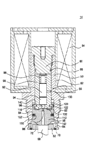
brought into close
contact with a valve seat 52.
[0049] The valve body 50 is formed in a cylindrical shape with its upper and
lower surfaces
opened. The upper surface of the valve body 50 is fitted with a core 60 for
sealing the upper
12
CA 03023442 2018-11-06
surface of the valve body 50. The lower outer circumferential surface of the
valve body 50 is
formed with a screw coupling portion 62 which is screwed with the main valve
body 10. An inlet
port 64 communicating with the second flow path 22 and through which the raw
material gas
enters and exits is formed on the lower side surface of the valve body 50.
[0050] The core 60 is screwed on the upper portion of the valve body 50 and a
first seal ring 66
is mounted on the outer circumferential surface thereof to prevent fluid from
flowing out.
10051] The inside of the valve body 50 has a first space portion 82 in which
the actuation unit
56 is mounted and a second space portion 84 in which the lower plunger 58 is
mounted, and
which is formed to have a larger inner diameter than the first space portion
82.
[0052] The valve seat 52 is formed with an exit port 68 which is fixed to the
lower surface of
the valve body 50 and through which the raw material gas is discharged. A
second seal ring 70
which is in close contact with the main valve body 10 to maintain sealability
is mounted on the
lower surface of the valve seat 52. A seat portion 72 in the shape of an
inclined surface in contact
with the lower plunger 58 is formed on the inner surface of the upper end of
the exit port 68 of
the valve seat 52.
[0053] The actuation unit 56 includes: an upper plunger 90 that is linearly
movable in the first
space portion 82 of the valve body 50 and linearly moves when power is applied
to the coil 54; a
moving member 92 which is inserted into the inner surface of the upper plunger
90 so as to be
linearly movable; a valve member 94 which is operated in association with the
moving member
92 and is linearly movably inserted into the inner surface of the upper
plunger 90, provided with
13
CA 03023442 2018-11-06
an actuation rod 96 for opening and closing an orifice at an end thereof; and
a spring 98 provided
between the moving member 92 and the core 60 to provide an elastic force such
that the
actuation rod 96 is brought into close contact with the orifice 86.
[0054] A partition wall portion 110 protruding in the circumferential
direction is formed at the
lower end of the upper plunger 90 inserted into the lower plunger 58 and a
chamber 112 in which
fluid flows is formed between the upper plunger 90 and the lower plunger 58.
100551 A latching pin 120 is formed with on a lower outer surface of the upper
plunger 90 and a
latching slot 122 through which the latching pin 120 is inserted and hooked is
formed on an
upper side of the lower plunger 58. Here, the latching slot 122 is formed to
secure a
predetermined space in the vertical direction so that the latching pin 120 can
be moved within a
preset range of the latching slot 122 in the vertical direction.
[0056] Thus, the upper plunger 90 and the lower plunger 58 are caught by the
latching pin 120
and prevented from being separated from each other.
[0057] The upper plunger 90 is formed with fluid passages 130 and 132 for
relieving the
pressure difference of the fluid flowing into a space between both the outer
surface and the inner
surface of the upper plunger 90. That is, when the fluid flows into the valve
body 50, the fluid
flows into a gap between the outer surface of the upper plunger 90 and the
inner surface of the
valve body 50 and a gap between the inner surface of the upper plunger 90 and
the moving
member 92.
[0058] Here, when the pressure of the fluid introduced into the outer portion
of the upper
14
CA 03023442 2018-11-06
plunger 90 and the pressure of the fluid introduced into the inner portion of
the upper plunger 90
are different from each other, the pressure difference interferes with the
linear movement of the
upper plunger 90, and thus the initial operation of the upper plunger 90 is
inaccurate to cause a
problem that the operation of the valve is not precise.
[0059] In the present disclosure, the upper plunger 90 is provided with fluid
passages 130 and
132 for relieving a pressure difference by communicating the inside and the
outside with each
other, so that both the internal pressure and the external pressure of the
upper plunger 90 are
always the same to thereby improve an operability of the upper plunger 90.
[0060] The fluid passages 130 and 132 for relieving the pressure difference
include: a first fluid
passage 130 formed so that both the outside and the inside of the upper
plunger 90 are
communicated with each other and a second fluid passage 132 formed in the
partitioning wall
portion 110 so that the outside of the upper plunger 90 and the chamber 112
are communicated
with each other.
100611 In the conventional solenoid valve, an actuation rod is formed on the
upper plunger so
that the actuation rod directly contacts the lower plunger. In this case, when
a high pressure is
applied to the upper plunger, the actuation rod of the upper plunger is
strongly impacted to the
lower plunger. When the actuation rod of the upper plunger repeatedly contacts
the lower
plunger with high pressure for opening and closing the orifice, the actuation
is damaged and the
lower plunger is also deformed by the impact, to thereby cause a problem that
the orifice hole is
clogged.
CA 03023442 2018-11-06
[0062] In order to solve this problem of the present disclosure, the valve
member 94 for opening
and closing the upper plunger 90 and the orifice 86 is separated, and the
valve member 94 is
disposed linearly movably on the inner surface of the upper plunger 90. The
moving member 92
having high durability is disposed on the valve member 94 so that the valve
member 94 is
brought into contact with the orifice to prevent the upper plunger 90 and the
lower plunger 58
from being damaged.
[0063] Here, the moving member 92 is formed of a strongly durable metal
material, and the
valve member 94 is formed of a non-metal material so as to prevent an impact
from being
generated upon contact with the lower plunger 58.
[0064] The lower plunger 58 is disposed linearly movably in the second space
portion 84 of the
valve body 50. An insertion groove portion 140 into which the upper plunger 90
is inserted
formed on an upper surface of the lower plunger, and a tight contact portion
142 adhering to the
valve sheet 52 is formed on a lower surface thereof.
[0065] An orifice 86, which is opened and closed by the actuation rod 96, is
formed
penetratively at the center of the lower plunger 58.
[0066] The latching pin 120 fixed to the upper plunger 90 is hooked to the
insertion groove 140
so that the latching slot 122 connecting between the upper plunger 90 and the
lower plunger 58 is
formed in the vertical direction, and the latching pin 120 is moved in the
latching slot 122 within
a preset range in the vertical direction.
[0067] The lower plunger 58 is provided with a fluid flow delay unit denoted
by reference
16
CA 03023442 2018-11-06
numerals 150 and 152 for delaying the flow of the fluid flowing into a gap
between the outer
surface of the lower plunger 58 and the inner surface of the valve body 50.
100681 The fluid flow delay unit includes a groove 150 formed on the outer
surface of the lower
plunger in the circumferential direction and a delay ring 152 inserted into
the groove 150 and
contacting the inner surface of the valve body 50.
[0069] Here, the delay ring 152 is inserted into the groove 150 so as to be
flowable so as to
delay the flow of the fluid flowing into the outer surface of the lower
plunger 58, to thereby
generate a pressure difference between the upper and lower portions of the
lower plunger 58.
[0070] As described above, as the flow of the fluid introduced into the lower
portion of the
lower plunger 58 is delayed by the delay ring 152 toward the upper portion of
the lower plunger
58, a pressure difference is generated between both the upper portion and the
lower portion of
the lower plunger 58, and the lower plunger 58 can be actuated by a pressure
difference before
the actuation by the electrical signal of the coil, so that the actuation of
the lower plunger 58 can
be smoothly performed.
[0071] The operation of the solenoid valve according to one embodiment of the
present
disclosure thus constructed will be described below.
[0072] First, as shown in FIG. 3, the lower plunger 58 is brought into close
contact with the
valve seat 52 and the actuation rod 96 is brought into close contact with the
orifice 86 by the
elastic force of the spring 98, and thus the second fluid path 22 is closed.
[0073] In this state, as shown in FIG. 4, when the coil 54 is energized, the
upper plunger 90 is
17
CA 03023442 2018-11-06
lifted and the valve member 94 inserted into the upper plunger 90 is lifted,
and accordingly the
orifice 86 is opened.
[0074] Then, the high-pressure fluid filled in the chamber 112 is discharged
through the orifice
86, and the fluid filled in the outside and inside of the chamber 112 and the
upper plunger 90 is
brought into a low-pressure state.
100751 Here, the inner and outer pressures of the upper plunger 90 are
equalized by the fluid
passages 130 and 132 formed in the upper plunger 90 at the time of linear
movement of the
upper plunger 90, movement of the upper plunger 90 is smoothly performed.
[0076] Further, as shown in FIG. 5, the high-pressure fluid filled in the
lower portion of the
lower plunger 58 is delayed by the delay ring 152 at a time of moving the
fluid to the upper
portion of the lower plunger 58, and the pressure difference is momentarily
generated between
both the upper and lower portions of the lower plunger 58. According to the
pressure difference,
the lower plunger 58 is moved prior to the movement in accordance with the
electrical signal of
the coil 54 to thus open the exit port 68 of the valve seat 52.
[0077] As described above, since the lower plunger 58 is moved by the pressure
difference
between the upper and lower portions of the lower plunger 58 before the
pulling force of the
upper plunger 90 by the electric signal of the coil 54 acts on the lower
plunger 58, the movement
of the lower plunger 58 is smoothly performed and thus the valve operation can
be smoothly
performed.
[0078] In addition, as shown in FIG. 6, a high-pressure fluid acting on the
lower portion of the
18
CA 03023442 2018-11-06
lower plunger 58 acts on the upper portion of the lower plunger 58 to urge the
high-pressure
fluid to be acted entirely on the lower plunger 58 and the upper plunger 90
and the exit port 68 is
opened to allow the fluid to pass through the second flow path 22.
100791 While the present disclosure has been particularly shown and described
with reference to
exemplary embodiments thereof, by way of illustration and example only, it is
clearly
understood that the present disclosure is not to be construed as limiting the
present disclosure,
and various changes and modifications may be made by those skilled in the art
within the
protective scope of the invention without departing off the spirit of the
present disclosure.
INDUSTRIAL APPLICABILITY
10080) According to the present disclosure, a fluid control solenoid valve is
provided in a high-
pressure vessel storing a raw material gas in a hydrogen fuel cell system to
control a flow of the
raw material gas when filling the raw material gas with the high-pressure
vessel, so that the
operation of the fluid control solenoid valve can be smoothly performed, and
the fluid control
solenoid valve can be prevented from being damaged by the pressure of the
fluid.
19