Note: Descriptions are shown in the official language in which they were submitted.
METHODS AND SYSTEMS FOR A PIN POINT FRAC SLEEVES SYSTEM
CROSS-REFERENCE TO RELATED APPLICATIONS
[0001] This application is related to US 14/987,559 filed 01/04/2016.
BACKGROUND INFORMATION
Field of the Disclosure
[0002] Example of the present disclosure relate to frac sleeve with set of
inner sleeves that
allow selective open and close of such sleeves where clusters of the same
sleeve to be
treated top to bottom.
Background
[0003] Hydraulic fracturing is the process of creating cracks or fractures in
underground
geological formations. After creating the cracks or fractures, a mixture of
water, sand,
and other chemical additives, are pumped into the cracks or fractures to
protect the
integrity of the geological formation and enhance production of the natural
resources.
The cracks or fractures are maintained opened by the mixture, allowing the
natural
resources within the geological formation to flow into a wellbore, where it is
collected
at the surface.
[0004] Additionally, during the fracturing process, tools may be pumped
through frac sleeves
to enhance the production of the natural resources. One of the tools pumped
through
the frac sleeves are frac-balls. The frac-balls are configured to block off or
close
portions of a well to allow pressure to build up, causing the cracks or
fractures in the
geological formations and in other cases to shut these openings and isolate
existing
fracture to prevent production of un-required fluid.
100051 Current or existing completion strings utilizing frac sleeves in
wellbores are comprised
of a plurality of frac sleeves, each having have tapered sidewalls. In order
to activate
each frac sleeve, properly sized frac-balls are pumped along with the mixture
inside of
the wellbore. Subsequent pumped frac-balls have a larger diameter. Thus,
current or
existing completion strings utilizing frac sleeves in wellbores require frac-
balls of
proper size to be sequentially pumped into a completion string.
CA 3023748 2020-04-06
CA 03023748 2018-11-08
WO 2017/222807 PCT/US2017/036182
[0006] When a properly sized frac-ball is positioned within a corresponding
frac sleeve, the
positioning of the frac-ball exerts pressure causing the frac sleeve
activation or
opening, consequently causing the pressure to fracture or crack in the
geological
formation. At the completion of each fracturing stage, a larger sized frac-
ball is
injected into the completion string, which opens up the next frac sleeve. This
process
repeats until all of the frac sleeves are opened, and multiple fractures are
created in
the wellbore.
[0007] Thus, conventional wellbores force fracturing to occur at the lowest
frac sleeve first.
This causes completion strings to be prone to accumulate undesired sand or
mixtures
in the wellbore after a fracking stage. Additionally, conventional wellbores
rely on
tapered frac sleeves corresponding to different sized frac-balls. This limits
the number
of stages in a completion string and frac rate due to the huge pressure drop
across the
frac sleeves with the smallest ball seats and limits the ability to
efficiently treat the
geological formation under consideration. After the multiple fractures are
created in
conventional wellbores, additional fractures cannot be created without
intervention for
mechanical activation.
[0008] In conjunction to [007], an expandable ball seat system is introduced
where in this
case, a group of sleeves with the same ball seat size are all opened together
and
treated together, hence not allowing each zone to be treated independently,
i.e.: pin
point.
[0009] Accordingly, needs exist for system and methods utilizing a frac-sleeve
with an upper
sleeve and a lower sleeve or more to allow the frac-sleeve of same size to be
used more
than once in the same string, while allowing each zone the frac sleeve
correspond to be
treated independently from the other, i.e: pin point.
2
CA 03023748 2018-11-08
WO 2017/222807 PCT/US2017/036182
SUMMARY
[00101 Embodiments disclosed herein describe a frac sleeve with ball seats.
More specifically,
embodiments include two inner sleeves within a frac sleeve configured to allow
a single
ball to treat a plurality of zones associated with a plurality of frac sleeves
while
independently pin pointing treatment for each zone. This may allow for the
frac sleeves
to be utilized heel to toe within a cluster comprised of many sleeves, and
with a
plurality of different clusters, wherein the clusters may be the whole well.
However, in
alternative embodiments, the frac sleeve may be utilized in toe to heel
configurations.
Embodiments may be implemented in either cemented or un-cemented applications
and in any well bore trajectory, i.e.: Vertical Wells, Horizontal Wells, etc.
[0011] Embodiments may include a frac sleeve with an outer sidewall and inner
sleeves. The
inner sleeves include a lower sleeve and an upper sleeve.
[0012] The outer sidewall may include an outer frac port, a production port,
multiple locking
mechanisms, and a linearly adjustable member. In embodiments, the production
port
may be angled to minimize the distance between second ends of the production
port
and the frac port, while increasing the distance between the first ends of the
production port and the frac port. In embodiments, the first ends of the
production
port and the frac port may be positioned within the frac sleeve, and the
second ends of
the production port and the frac port may be positioned outside of the frac
sleeve.
[0013] The inner lower sleeve may include a lower frac port and a first ball
seat.
[0014] The inner upper sleeve may include an upper production port and a
second ball seat.
In embodiments, the first ball may be smaller than the first ball.
[0015] In embodiments, a first frac-ball may be dropped within the inner
sleeves, pass
through the second ball seat, and be positioned on the first ball seat. When
the first
frac-ball is positioned on the first ball seat, pressure may be applied within
the frac
sleeve to compress the linearly adjustable member.
[0016] Responsive to compressing the linearly adjustable member, the lower
inner sleeve may
slide linearly within the outer sidewall, while the upper inner sleeve may
remain in a
fixed position.
[0017] In embodiments, responsive to linearly moving the lower inner sleeve,
the outer frac
port may become aligned with the lower frac port. When the outer frac port and
lower
frac port are aligned, fracking fluid may be transmitted from a position
within the
inner sleeve to a position outside of the outer sidewall via the aligned frac
ports.
3
CA 03023748 2018-11-08
WO 2017/222807 PCT/US2017/036182
[0018] In embodiments, as the pressure within the frac sleeve is decreased,
the Linearly
adjustable member may expand. Responsive to expanding the linearly adjustable
member, the lower inner frac sleeve may slide upward causing the first ball
seat to be
aligned with a first locking mechanism.
[00191 When the first ball seat is aligned with the first locking mechanism,
the first ball seat
may open horizontally into the first locking mechanism. Once the first ball
seat open,
a diameter of the lower ball seat may have a diameter that is greater than the
first
frac-ball. This may allow the first frac-ball to slide through the linearly
adjustable
member and the first ball seat. Once sliding through, the first frac-ball may
fall
through the first frac sleeve into a lower positioned, second frac sleeve.
[0020] Additionally, when the linearly adjustable member is elongate or
contract, the lower
port may be aligned with the angled production port, while the lower frac
sleeve blocks
passage of fluid through the outer frac port.
[0021] In embodiments, a second frac-ball may be dropped within the inner
sleeves, and be
positioned on the second ball seat. When the second frac-ball is positioned on
the
second ball seat, pressure may be applied within the frac sleeve. This
pressure may
move the upper inner frac sleeve downward. Responsive to sliding the upper
inner
sleeve downward, the upper production port may be aligned with the lower frac
port
and the angled production port. This may allow the angled production port to
be
utilized.
[0022] To this end, embodiments may utilize two different ports, wherein a
first port may be
used for fracturing and stimulation and a second port may be used for
production.
The two inner frac sleeves may be used independently to open and close the
different
ports. When the inner frac sleeves are not meant to be utilized, the inner
ports may
not align with the ports within the outer sidewall.
[0023] Additionally, different stages of frac sleeves may utilize different
sized frac balls.
Accordingly, a first frac ball for a first frac-sleeve may be used as the
second frac ball
for a second frac-sleeve, wherein the first frac-sleeve may be positioned
above the
second frac-sleeve.
[0024] In other words, after a frac ball is utilized to open the fracturing
port of the first frac-
sleeve, the frac ball may drop through the first frac-sleeve and enter into
the second
frac-sleeve. Once the frac ball is within the second frac-sleeve, the frac
ball may be
utilized to open the production port of the subsequent, second frac-sleeve.
Thus, after
4
CA 03023748 2018-11-08
WO 2017/222807 PCT/US2017/036182
achieving fracturing of an upper frac-sleeve, the frac ball may drop to a
lower frac
sleeve to open the production ports for all the subsequent frac sleeves. A
lowest frac
sleeve in a cluster, may have a solid second ball seat. This may prevent a
frac-ball
from passing through the lowest frac-sleeve.
[0025] Utilizing the frac-balls, embodiments may allow the fracking process to
occur from an
uppermost frac sleeve to a lowermost frac sleeve. This may allow excess sand
and fluid
to flow downward, which may save fluid and leaving less sand in the well.
Additionally,
utilizing embodiments a seamless infinite number of fracking sleeves may
utilize the
frac-balls for production. This may allow more fractures across a completion
string.
[0026] These, and other, aspects of the invention will be better appreciated
and understood
when considered in conjunction with the following description and the
accompanying
drawings. The following description, while indicating various embodiments of
the
invention and numerous specific details thereof, is given by way of
illustration and not
of limitation. Many substitutions, modifications, additions or rearrangements
may be
made within the scope of the invention, and the invention includes all such
substitutions, modifications, additions or rearrangements.
CA 03023748 2018-11-08
WO 2017/222807 PCT/US2017/036182
BRIEF DESCRIPTION OF THE DRAWINGS
[0027] Non-limiting and non-exhaustive embodiments of the present invention
are described
with reference to the following figures, wherein like reference numerals refer
to like
parts throughout the various views unless otherwise specified.
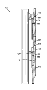
[0028] FIGURE 1 depicts a frac sleeve, according to an embodiment.
[0029] FIGURE 2 depicts a first operation utilizing a frac sleeve, according
to an embodiment.
[0030] FIGURE 3 depicts a second operation utilizing a frac sleeve, according
to an
embodiment.
[0031] FIGURE 4 depicts a third operation utilizing a frac sleeve, according
to an
embodiment.
[0032] FIGURE 5 depicts a fourth operation utilizing a frac sleeve, according
to an
embodiment.
[0033] FIGURE 6 depicts a fifth operation utilizing a frac sleeve, according
to an embodiment.
[0034] FIGURE 7 depicts a sixth operation utilizing a frac sleeve, according
to an
embodiment.
[0035] FIGURE 8 depicts a frac sleeve, according to an embodiment, according
to an
embodiment.
[0036] FIGURE 9 depicts a frac sleeve, according to an embodiment, according
to an
embodiment.
[0037] FIGURE 10 depicts a first operation utilizing a frac sleeve, according
to an
embodiment.
[0038] FIGURE 11 depicts a second operation utilizing a frac sleeve, according
to an
embodiment.
[0039] FIGURE 12 depicts a third operation utilizing a frac sleeve, according
to an
embodiment.
[0040] FIGURE 13 depicts a fourth operation utilizing a frac sleeve, according
to an
embodiment.
[0041] FIGURE 14 depicts a fifth operation utilizing a frac sleeve, according
to an
embodiment.
[0042] FIGURE 15 depicts a sixth operation utilizing a frac sleeve, according
to an
embodiment.
[0043] FIGURE 16 depicts a frac sleeve, according to an embodiment, according
to an
6
CA 03023748 2018-11-08
WO 2017/222807 PCT/US2017/036182
embodiment.
[0044] FIGURES 17-20 depict tables indicating stages comprised of a plurality
of frac sleeves.
[0045] Corresponding reference characters indicate corresponding components
throughout
the several views of the drawings. Skilled artisans will appreciate that
elements in the
figures are illustrated for simplicity and clarity and have not necessarily
been drawn to
scale. For example, the dimensions of some of the elements in the figures may
be
exaggerated relative to other elements to help improve understanding of
various
embodiments of the present disclosure. Also, common but well-understood
elements
that are useful or necessary in a commercially feasible embodiment are often
not
depicted in order to facilitate a less obstructed view of these various
embodiments of
the present disclosure.
7
CA 03023748 2018-11-08
WO 2017/222807 PCT/US2017/036182
DETAILED DESCRIPTION
[0046] In the following description, numerous specific details are set forth
in order to provide
a thorough understanding of the present invention. It will be apparent,
however, to
one having ordinary skill in the art that the specific detail need not be
employed to
practice the present invention. In other instances, well-known materials or
methods
have not been described in detail in order to avoid obscuring the present
invention.
[0047] Examples of the present disclosure relate to a frac sleeve with various
inners sleeves
and ball seats. More specifically, embodiments include inner sleeves and ball
seat
within a frac sleeve configured to allow a single frac-ball to independently
open or
close plurality of zones associated with a plurality of frac sleeves while
still treat or
pinpoint each zone independent from the other.
[0048] Turning now to FIGURE 1, FIGURE 1 depicts a frac sleeve 100, according
to an
embodiment. In embodiments, a wellbore may include a plurality of frac sleeves
100,
which may be vertically/linearly aligned across their axis with one another.
The
plurality of frac sleeves 100 may be vertically/linearly aligned such that a
first frac
sleeve 100 is positioned above a second frac sleeve 100. Accordingly, the frac
sleeves
100 may be aligned in parallel to a longitudinal axis of frac sleeve 100. Each
frac
sleeve 100 may be utilized to control the flow of fluid, gases, mixtures, etc.
within a
stage of a wellbore.
[0049] Frac sleeve 100 may include outer sidewall 110, lower inner sleeve 120,
upper inner
sleeve 130. Outer sidewall 110, lower inner sleeve 120, upper inner sleeve 130
may
form a hollow chamber, channel, conduit, passageway, etc. The hollow chamber
may
extend from a top surface of outer sidewall 110 and upper inner sleeve 130 to
a lower
surface of outer sidewall 110 and lower inner sleeve 120. Furthermore, lower
inner
sleeve 120 may not be coupled or sealed with upper inner sleeve 130. This may
allow
the inner sleeves to operate independently, and prevent Hydraulic
lock/atmospheric
effects within the hollow chamber.
[0050] Lower inner sleeve 120 may be positioned within the hollow channel, and
be
positioned adjacent to outer sidewall 110. In embodiments, an outer diameter
of lower
inner sleeve 120 may be positioned adjacent to an inner diameter of outer
sidewall
110. Outer sidewall 110 and lower inner sleeve 120 may have parallel
longitudinal
axis, and may not include tapered sidewalls. In embodiments, lower inner
sleeve 120
8
CA 03023748 2018-11-08
WO 2017/222807 PCT/US2017/036182
may be positioned below upper inner sleeve 130. Lower inner sleeve 120 may
include
lower frac port 122 and first ball seat 124.
[0051] Lower frac port 122 may be an opening, orifice, etc. extending through
lower inner
sleeve 120. Lower frac port 122 may be configured to control the flow of
fluid, fracking
materials, and natural resources through the hollow chamber. In embodiments,
lower
frac port 122 may be configured to be misaligned and aligned with outer frac
port 112.
When lower frac port 122 is misaligned with outer frac port 112, the sidewalls
of inner
sleeve 120 may form a seal, and may not allow fluid to flow from the hollow
into the
geological formations via outer frac port 112.
[0052] First ball seat 124 may be configured to secure a frac-ball within the
hollow chamber.
First ball seat 124 may be comprised of two semi-circles with a hollow center,
wherein
the hollow center of first ball seat 124 is configured to have a variable
diameter. In
other words, first ball seat 124 may be substantially donut shaped. However,
in other
embodiments, the ball seats may be any shape or size with a passageway
extending
through the ball seat.
[0053] The variable diameter of first ball seat 124 may change based on a
diameter of a
structure positioned adjacent to the outer diameter circumference of first
ball seat
124. Thus, first ball seat 124 may change to have a circumference
substantially the
same size as the structure positioned adjacent to the outer diameter of first
ball seat
124. When first ball seat 124 is positioned in the hollow chamber, first ball
seat 124
may have a first diameter. When first ball seat 124 is positioned within first
locking
mechanism 116, first ball seat 124 may have a second diameter, wherein the
first
diameter is smaller than the second diameter.
[0054] Upper inner sleeve 130 may be positioned within the hollow channel, and
be
positioned adjacent to outer sidewall 110. In embodiments, an outer diameter
of upper
inner sleeve 130 may be positioned adjacent to an inner diameter of outer
sidewall
110. Outer sidewall 110 and upper inner sleeve 130 may have parallel
longitudinal
axis, and may not include tapered sidewalls. In embodiments, upper inner
sleeve 130
may be positioned above lower inner sleeve 120. Upper inner sleeve 130 may
include
second ball seat 134.
[0055] Second ball seat 134 may be configured to secure a frac-ball within the
hollow
chamber. Second ball seat 134 may be comprised of two semi-circles with a
hollow
center, wherein the hollow center of second ball seat 134 is configured to
have a
9
CA 03023748 2018-11-08
WO 2017/222807 PCT/US2017/036182
variable diameter. In other words, second ball seat 134 may be substantially
donut
shaped.
[0056] The variable diameter of second ball seat 134 may change based on a
diameter of a
structure positioned adjacent to the outer diameter circumference of second
ball seat
134. Thus, second ball seat 134 may change to have a circumference
substantially the
same size as the structure positioned adjacent to the outer diameter of second
ball
seat 134. When second ball seat 134 is positioned adjacent to the hollow
chamber,
second ball seat 134 may have a third diameter. When second ball seat 134 is
positioned within second locking mechanism 117, second ball seat 134 may have
a
fourth diameter, wherein the third diameter is smaller than the fourth
diameter.
Additionally, the third diameter may be greater than the first diameter of the
first ball
seat 124. Therefore, a frac ball may be able to pass through second ball seat
134 but
not first ball seat 124.
[0057] Outer sidewall 110 may include frac port 112, production port 114,
first locking
mechanism 116, second locking mechanism 117, and linearly adjustable member
118.
[0058] Frac port 112 may be an opening, orifice, etc. extending through outer
sidewall 110.
Frac port 112 may be configured to control the flow of fluid, fracking
materials,
natural resources and any fluid through the hollow chamber. In embodiments,
frac
port 112 may be configured to be misaligned and aligned with a lower port 122
positioned through lower inner sleeve 120. When misaligned with the lower port
122
within lower inner sleeve 120, frac port 112 may be sealed. When aligned with
the
lower port 122 within lower inner sleeve 120, frac port 112 may allow frac
sleeve 100
to be operational.
[0059] Production port 114 may be an opening, orifice, etc. extending through
outer sidewall
110. Production port 114 may be positioned above frac port 112. Production
port 114
may be filled with or include variable material. For example, production port
114 may
be filled with a dissolvable material that may be removed after a certain
amount of
time or after fluid pressure is applied to the removable material or after
certain fluid is
pumped around. In other embodiments, the removable material may be a door,
flap,
entrance, etc. that is configured to extend through the production port 114.
The door
may seal production port 114 when extended. However, the door may be
configured to
rotate, move, etc. to be recessed in outer sidewall 110, etc. When rotated or
moved, the
door may form an opening through production port 114.
CA 03023748 2018-11-08
WO 2017/222807 PCT/US2017/036182
[0060] In embodiments, production port 114 may be configured to be misaligned
and aligned
with a sidewall of upper inner sleeve 120. When misaligned with sidewall of
upper
inner sleeve 120, production port 114 may be sealed. However, when an upper
edge of
upper inner sleeve 120 is positioned below production port 114, production
port 114
may be utilized to receive materials from outside of outer sidewall 110 or
from inside
of the sleeve 110. Thus, allowing frac sleeve 100 to be operational. In
embodiments,
production port 114 and frac port 112 may not be operational simultaneously.
[0061] First locking mechanism 116 may be an opening, orifice, recess, profile
etc. extending
from the inner diameter of outer sidewall 110 towards the outer diameter of
outer
sidewall 110. However, the opening associated with first locking mechanism 116
may
not extend completely through outer sidewall 110. Accordingly, a diameter
across first
locking mechanism 116 may be larger than the diameter across the inner
diameter of
outer sidewall 110, but less than the diameter across the outer diameter of
outer
sidewall 110. First locking mechanism 116 may be a recession within outer
sidewall
110 that is configured to receive first ball seat 124. In embodiments, first
locking
mechanism 116 may be positioned below frac port 112, and above linearly
adjustable
member 118. Responsive to first ball seat 124 being horizontally aligned with
first
locking mechanism 116, the diameter of first ball seat 124 may enlarge with
first
locking mechanism 116.
[0062] Second locking mechanism 117 may be an opening, orifice, recess,
profile etc.
extending from the inner diameter of outer sidewall 110 towards the outer
diameter of
outer sidewall 110. However, the opening associated with Second locking
mechanism
117 may not extend completely through outer sidewall 110. Accordingly, a
diameter
across a second locking mechanism 117 may be larger than the diameter across
the
inner diameter of outer sidewall 110, but less than the diameter across the
outer
diameter of outer sidewall 110. In embodiments, second locking mechanism 117
may
be positioned above frac port 112 and below production port 114. Second
locking
mechanism 117 may be a recession within outer sidewall 110 that is configured
to
receive second ball scat 134. Responsive to second ball scat 134 being
horizontally
aligned with second locking mechanism 117, the diameter of second ball seat
134 may
change within second locking mechanism 117.
[0063] Linearly adjustable member 118 may be a device or fluid chamber that is
configured
to linearly move lower inner sleeve 120. For example, linearly adjustable
member 118
11
CA 03023748 2018-11-08
WO 2017/222807 PCT/US2017/036182
may be a spring, hydraulic lift, etc. Linearly adjustable member 118 may be
positioned
below first locking mechanism 116. However, in other embodiment's Linearly
adjustable member 118 may be positioned in various places in relation to inner
sleeve.
In embodiments, a lower surface of Linearly adjustable member 118 may be
positioned
adjacent to a lower ledge, and an upper surface of Linearly adjustable member
118
may be positioned adjacent to an upper ledge, projection, protraction, etc. on
lower
inner sleeve 120. Responsive to being compressed or elongated, lower inner
sleeve 120
may slide within outer sidewall 110. When Linearly adjustable member 118 is
compressed or elongated, first ball seat 124 may correspondingly move.
[0064] FIGURES 2-7 depict phases of a method 200 for operating a sliding frac
sleeve 100.
The operations of the method depicted in FIGURES 2-7 are intended to be
illustrative.
In some embodiments, the method may be accomplished with one or more
additional
operations not described, and/or without one or more of the operations
discussed.
Additionally, the order in which the operations of the method are illustrated
in
FIGURES 2-7 and described below is not intended to be limiting. Elements
depicted in
FIGURES 2-7 may be described above. For the sake of brevity, a further
description of
these elements is omitted.
[0065] FIGURE 2 depicts a first operation 210 utilizing frac sleeve 100. At
operation 210, frac
sleeve 100 may be positioned within a geological formation with natural
resources that
are desired to be extracted, or across a geological formation where injection
of fluid is
desired.
[0066] In operation 210, Linearly adjustable member 118 may be partially
extended.
Additionally, the ports within lower inner sleeve 120 and upper inner sleeve
130 may
not align with the port on outer sidewall 110. Thus, the hollow chamber within
frac
sleeve 100 may be sealed from the geological formation.
[0067] FIGURE 3 depicts a second operation 220 utilizing frac sleeve 100. At
operation 220, a
first frac-ball 305 may be inserted within the hollow chamber. The first frac
ball 305
may enter the hollow chamber from a first end of frac sleeve 100. The first
frac-ball
305 may pass through the second ball seat 134. The frac-ball 305 may pass
through
the second ball seat 134 due to the second ball seat 134 having a larger
diameter than
the first ball seat 124.
[0068] FIGURE 4 depicts a third operation 230 utilizing frac sleeve 100. At
operation 230, the
first frac-ball 305 may be positioned on first ball seat 124. While the frac-
ball 305 is
12
CA 03023748 2018-11-08
WO 2017/222807 PCT/US2017/036182
positioned on first ball seat 124, the pressure within the hollow chamber may
be
increased. This may force linearly adjustable member 118 to compress and lower
inner sleeve 120 to slide within the hollow chamber.
[0069] FIGURE 5 depicts a fourth operation 240 utilizing frac sleeve 100. At
operation 240,
pressure within the hollow chamber may build up due to first frac-ball 305
forming a
seal on a second end of the hollow chamber by closing an opening within the
center of
the first ball seat 124.
[0070] As the pressure within the hollow chamber increases, the pressure may
break sheer
screws or other elements holding lower inner sleeve in place allowing linearly
adjustable member 118 to compress. Responsive to linearly adjustable member
118
compressing, lower inner sleeve 120 may slide downward to align lower frac
port 122
with outer frac port 112.
[0071] FIGURE 6 depicts a fifth operation 250 utilizing frac sleeve 100. At
operation 250, the
pressure within the hollow chamber may decrease. This may allow linearly
adjustable
member 118 to be elongated and rise above its initial vertical offset. When
linearly
adjustable member 118 is elongated, first ball seat 124 may be horizontally
aligned
with first locking mechanism 116. When aligned, linearly adjustable member 118
may
expand to increase the inner and outer circumference of first ball seat 124.
This may
cause lower inner sleeve 120 to be locked in place, wherein the positioning of
lower
inner sleeve 120 and outer sidewall 110 may misalign lower frac port 122 with
outer
frac port 112 to not form a passageway.
[0072] Furthermore, when the inner circumference of first ball seat 124
increases, the first
frac ball 305 may move downward through the hollow chamber and through the
second end of frac sleeve 100.
[0073] The above operations may be repeated a plurality of times for multiple
frac-sleeves,
wherein the same first frac ball may be utilized to align multiple frac ports
within
inner sleeves and outer frac ports within outer sidewalls.
[0074] FIGURE 7 depicts a sixth operation 260 utilizing frac sleeve 100. At
operation 260, a
second frac-ball 705 may be inserted within the hollow chamber. The second
frac ball
may enter the hollow chamber from a first end of frac sleeve 100, wherein the
second
frac ball has a larger diameter than the first frac ball. Pressure within the
hollow
chamber may build up due to the second frac-ball forming a seal on a second
end of
13
CA 03023748 2018-11-08
WO 2017/222807 PCT/US2017/036182
the hollow chamber by closing an opening within the center of the second ball
seat
134.
[0075] As the pressure within the hollow chamber increases, the pressure may
break sheer
screws or other elements holding upper inner sleeve 130. Responsive to the
sheer
screws breaking, upper inner sleeve 130 may slide downward to position an
upper
surface of upper inner sleeve 130 below production port 114. When upper inner
sleeve
130 is positioned below production port 114, frac sleeve 100 may be open for
production or to allow various formation treatment.
[0076] Furthermore, when upper inner sleeve 130 is positioned below production
port 114,
second ball seat 134 may be horizontally aligned with second locking mechanism
117.
When aligned, second ball seat 134 may change to increase the inner and outer
circumference of second ball seat 134. This may cause upper inner sleeve 130
to be
locked in place. Additionally, when the inner circumference of second ball
seat 134
increases, the second frac ball may move downward through the hollow chamber
and
through the second end of frac sleeve 100.
[0077] FIGURE 8 depicts a frac sleeve 800, according to an embodiment.
Elements depicted
in FIGURE 8 may be substantially the same as those described above. For the
sake of
brevity an additional description of those elements is omitted.
[0078] Frac sleeve 800 may include holes 820 in outer sidewall 810. The holes
820 may be
utilized to provide a passageway between the production port and the frac port
within
outer sidewall 810, such that the production port and frac port may be in
communication with each other. Holes 820 may extend through outer sidewall 810
from a lower surface of the production port to an upper surface of the frac
port in a
direction that is in parallel to the hollow chamber.
[0079] FIGURE 9 depicts a frac sleeve 900, according to an embodiment.
Elements depicted
in FIGURE 9 may be substantially the same as those described above. For the
sake of
brevity an additional description of those elements is omitted.
[0080] Frac sleeve 900 may include an outer sidewall 910, lower inner sleeve
920, upper
inner sleeve 930, and hydraulic vent 940.
[0081] Outer sidewall 910 may include frac port 912, angled production port
914, first
locking mechanism 116, second locking mechanism 117, Linearly adjustable
member
118.
14
CA 03023748 2018-11-08
WO 2017/222807 PCT/US2017/036182
[0082] Frac port 912 may be positioned below angled production port 914.
Angled production
port 914 may be positioned at a downward slope from the hollow chamber towards
the
circumference of outer sidewall 910. Accordingly, a distance between the first
ends of
angled production port 914 and frac port 912 may be greater than a distance
between
the second ends of angled production port 914 and frac port 912. This may
assist in
well utilization, production, injection, fracking, etc.by having a production
port being
in closer proximity with the point of fracking.
[0083] Lower inner sleeve 920 may include a lower frac port 922. Lower frac
port 922 may be
initially configured to be positioned between the first ends of frac port 912
and
production port, wherein an inner surface of lower frac port 922 is covered by
upper
inner sleeve 930 in the initial position. Responsive to lower inner sleeve 920
sliding
downward, lower frac port 922 may be horizontally aligned with frac port 912
and
positioned below a lower surface of upper frac sleeve 930.
[0084] Upper inner sleeve 930 may include an upper production port 932. Upper
production
port 932 may be configured to be initially positioned above a first end of
production
port 914. Responsive to upper inner sleeve 930 sliding downward and lower
inner
sleeve 920 sliding upward, upper production port 932 may be aligned with lower
frac
port 922 and production port 914.
[0085] Hydraulic vent 940 may be positioned between upper inner sleeve 930 and
the outer
sidewall. In embodiments, hydraulic vent 940 may include a passageway
extending
from the hollow inner chamber into a cavity between upper inner sleeve 930 and
the
outer sidewall. Hydraulic vent 940 may include a screen that is configured to
not allow
sand or other solid materials to enter the cavity, but allow fluid to enter
and exit the
cavity. Responsive to fluid entering and exiting the cavity, the fluid may be
utilized to
move the sleeves or allow sleeves to freely move independently from each
other. In
embodiments, responsive to the movement of upper inner sleeve 930 and lower
inner
sleeve 920 the height of the cavity may increase and decrease.
[0086] FIGURES 10-15 depict phases of a method 1000 for operating a sliding
frac sleeve
900. The operations of the method depicted in FIGURES 10-15 are intended to be
illustrative. In some embodiments, the method may be accomplished with one or
more
additional operations not described, and/or without one or more of the
operations
discussed. Additionally, the order in which the operations of the method are
illustrated
in FIGURES 10-15 and described below is not intended to be limiting. Elements
CA 03023748 2018-11-08
WO 2017/222807 PCT/US2017/036182
depicted in FIGURES 10-15 may be described above. For the sake of brevity, a
further
description of these elements is omitted.
[0087] FIGURE 10 depicts a first operation 1010 utilizing frac sleeve 900. At
operation 1010,
frac sleeve 900 is in a first position. In the first position, frac port 912
and production
port are misaligned with both lower frac port 922 and 932, which are also
misaligned.
[0088] FIGURE 11 depicts a second operation 1020 utilizing frac sleeve 900. At
operation
220, a frac-ball 1105 may be dropped within the hollow chamber. Frac-ball 1105
may
enter the hollow chamber within frac sleeve 900 via an opening at the proximal
end of
frac sleeve 900, and fall towards the distal end of frac sleeve 900. In
embodiments, the
proximal end of frac sleeve 900 may be coupled to a distal end of another frac
sleeve
900, or frac sleeve 900 may be the first frac sleeve 900 in a completion
string.
[0089] Furthermore, at operation 1020, frac ball 1105 may pass through second
ball seat
934, due to second ball seat 934 having an open inner circumference greater
than that
of frac ball 1105.
[0090] FIGURE 12 depicts a third operation 1030 utilizing frac sleeve 900. At
operation 1030,
frac-ball 1105 may land on an upper surface of first ball seat 924, wherein
first ball
seat 924 may secure frac-ball 1105 in place. Furthermore, at operation 1030,
the
outer diameter of first ball seat 924 may be substantially the same as the
diameter of
the inner diameter of outer sidewall 110. Additional, the inner circumference
of first
ball seat 924 may be less than the circumference of frac ball 1105.
[0091] Additionally, at operation 1030 pressure within the hollow chamber may
build up due
to frac ball 1105 forming a seal on a second end of the hollow chamber by
closing an
opening within the center of the first ball seat 924.
[0092] FIGURE 13 depicts a fourth operation 1041) utilizing frac sleeve 900.
At operation
1040, the pressure within the hollow chamber may increase to compress linearly
adjustable member 918. This may force slide lower frac sleeve 920 downward.
When
lower inner sleeve 920 is slid downward into a second position, lower frac
port 922
may be horizontally aligned with frac port 912 and positioned below a lower
surface of
upper frac sleeve 930. Furthermore, the movement of lower frac sleeve 920 may
be
independent of the movement of upper frac sleeve 930, such that upper frac
sleeve
930 remains fixed in place.
[0093] FIGURE 14 depicts a fifth operation 1050 utilizing frac sleeve 900. At
operation 1050,
the pressure within the hollow chamber may decrease allowing linearly
adjustable
16
CA 03023748 2018-11-08
WO 2017/222807 PCT/US2017/036182
member 918 to elongate. When linearly adjustable member 918 is elongated,
first ball
seat 924 may be horizontally aligned with first locking mechanism 916. When
aligned,
first ball seat 924 may change to increase the inner and outer circumference
of first
ball seat 924. This may cause lower inner sleeve 920 to be locked in place.
Furthermore, when the inner circumference of first ball seat 924 increases,
the frac
ball 1105 may move downward through the hollow chamber and through the second
end of frac sleeve 900.
[0094] Additionally, when first ball seat 924 is secured in place, lower frac
port 922 may be
aligned within production port 114. However, upper inner sleeve 930 may block
a
passageway through the aligned ports.
[0095] FIGURE 15 depicts a sixth operation 1060 utilizing frac sleeve 900. At
operation 1060,
a second frac ball 1505 may be dropped within the hollow chamber, and be
positioned
on second ball seat 134. Responsive to positioning second frac ball 1505 on
second
ball seat 934, the pressure within the hollow chamber may slide upper inner
sleeve
930 downward to be horizontally aligned with second locking mechanism 917.
When
aligned, second ball seat 934 may change to increase the inner and outer
circumference of second ball seat 934. This may cause upper inner sleeve 930
to be
locked in place. Furthermore, when the inner circumference of second ball seat
934
increases, the frac ball 1505 may move downward through the hollow chamber and
through the second end of frac sleeve 900.
[0096] Additionally, when upper inner sleeve 930 slides downward upper frac
port 932 may
be aligned with lower frac port 922 and production port 114 allowing for
utilization of
frac sleeve 900, i.e.: Production, injection, etc.
[0097] FIGURE 16 depicts a frac sleeve 1600, according to an embodiment.
Elements
depicted in FIGURE 16 may be substantially the same as those described above.
For
the sake of brevity an additional description of those elements is omitted.
[0098] Frac sleeve 1600 may include an indexing system. The indexing system
may be
configured to allow a single ball size to be used per sleeve and/or cluster of
frac
sleeves. This may increase the total number of frac sleeves that can be run
per string.
The indexing system may include a first indexing seat 1660 and a second
indexing
seat 1650, wherein the first indexing seat 1660 and second indexing seat 1650
may be
retractable ball seats.
17
CA 03023748 2018-11-08
WO 2017/222807 PCT/US2017/036182
[0099] In embodiments, first indexing seat 1660 may initially have the same
circumferences
as the first ball seat because the hollow inner chamber may have the same
circumference at the positioning of first indexing seat 1660 and the first
ball seat. In
other words, the hollow inner chamber at position 1665 may have the same
circumference at a position of the first ball seat. However, the second
indexing seat
1650 may initially have greater inner and outer circumferences than that of
first
indexing seat 1660 due to their being a recession 1655 within the outer
sidewall.
[00100] Responsive to a frac ball being inserted into the frac sleeve, the
frac ball may pass
through the second indexing seat 1650 and be positioned on first indexing seat
1660.
When pressure within the hollow chamber builds, the upper inner sleeve may
linearly
slide downward such that the first indexing seat 1660 is aligned with a second
locking
mechanism. This may cause second indexing seat 1660 to enlarge, allowing the
frac
ball to slide through the hollow chamber. Furthermore, when the upper inner
sleeve
moves linearly, second indexing seat 1650 may be aligned with projection 1670.
Because the diameter within the hollow chamber across projection 1670 is
smaller
than that across recession 1655, the inner circumference and the outer
circumference
of second indexing seat 1650 may decrease.
[00101] Once all the sleeves in a cluster are activated, a subsequent frac
ball of the same size
may enter the hollow chamber and be positioned on the second indexing seat
1650.
When pressure within the hollow chamber builds, the upper inner sleeve may
linearly
slide downward such that the second indexing seat 1650 is aligned with a third
locking mechanism 1680. This may cause second indexing seat 1650 to enlarge,
allowing the subsequent frac ball to slide through the hollow chamber.
[00102] This may allow the use of a frac ball of the same size to activate the
upper and lower
sleeves, while maintain the same upper ball seat size to subsequently drop the
same
size frac ball through the hollow chamber. Accordingly, a single size frac
ball may be
utilized per sleeve and/or per cluster of sleeves, which may increase the
total number
of sleeves that may be operated.
[00103] FIGURE 17-20 depicts tables indicating stages comprised of a plurality
of frac sleeves.
Specifically, FIGURE 17 depicts a table 1700 indicating stages 1710 comprised
of a
plurality of frac sleeves 1720. In embodiments, stage 1 may be the highest
most stage
in a completion tree and stage 3 may be the lowest most stage in a completion
tree.
18
CA 03023748 2018-11-08
WO 2017/222807 PCT/US2017/036182
[00104] Each of the frac sleeves 1720 includes two sizing a frac balls 1730,
1740. A first,
smaller frac ball 1730 may be configured to be positioned on a first ball
seat, and a
second larger frac ball 1740 may be configured to be positioned on a second
ball seat.
[00105] As shown in table 1700, the smaller frac ball associated with a higher
stage may
correspond with the sizing of a larger frac ball associated with a lower
stage. For
example, a smaller frac ball associated with sleeve 5 may have a big sized
diameter,
whereas the larger frac ball associated with sleeve 6, at a lower stage, may
correspond
with the same big size diameter. This may allow smaller frac balls of higher
stages to
be passed down through stages to minimize the number of frac balls required.
[00106] As shown in FIGURE 18, the smaller frac ball associated with a
fracking port of a
higher stage may be larger than the sizing of a larger frac ball for a
production port
associated with a lower stage.
[00107] As shown in FIGURE 19, a smaller frac ball associated with a frac port
may be the
same throughout each stage and cluster. However, the sizing of a larger frac
ball
associated with a production port may decrease from stage to stage.
[00108] As shown in FIGURE 20, frac balls associated with a highest most stage
may be the
same size for both the frac port and production port, wherein this size is
larger than
frac balls associated with lower stages.
[00109] Reference throughout this specification to "one embodiment", "an
embodiment", "one
example" or "an example" means that a particular feature, structure or
characteristic
described in connection with the embodiment or example is included in at least
one
embodiment of the present invention. Thus, appearances of the phrases ''in one
embodiment", "in an embodiment", "one example'' or "an example" in various
places
throughout this specification are not necessarily all referring to the same
embodiment
or example. Furthermore, the particular features, structures or
characteristics may be
combined in any suitable combinations and/or sub-combinations in one or more
embodiments or examples. In addition, it is appreciated that the figures
provided
herewith are for explanation purposes to persons ordinarily skilled in the art
and that
the drawings are not necessarily drawn to scale.
[00110] Although the present technology has been described in detail for the
purpose of
illustration based on what is currently considered to be the most practical
and
preferred implementations, it is to be understood that such detail is solely
for that
purpose and that the technology is not limited to the disclosed
implementations, but,
19
CA 03023748 2018-11-08
WO 2017/222807 PCT/US2017/036182
on the contrary, is intended to cover modifications and equivalent
arrangements that
are within the spirit and scope of the appended claims. For example, it is to
be
understood that the present technology contemplates that, to the extent
possible, one
or more features of any implementation can be combined with one or more
features of
any other implementation.