Note: Descriptions are shown in the official language in which they were submitted.
OPTICAL FIBER WITH CLADDING-EMBEDDED LIGHT-CONVERGING STRUCTURE FOR
LATERAL OPTICAL COUPLING
TECHNICAL FIELD
[0001] The technical field generally relates to optical fibers, and more
particularly, to optical fiber
coupling techniques for use in various applications including, but not limited
to, integrated
photonics applications.
BACKGROUND
[0002] The transmission of optical signals between optical fibers and
integrated optical
waveguides poses several technological challenges, and various approaches have
been
suggested to improve light coupling efficiency. One type of approach uses
diffraction gratings to
couple light vertically, or nearly vertically, between a single-mode optical
fiber and an integrated
waveguide. In a typical configuration, the optical fiber is disposed
vertically, or nearly vertically,
over the waveguide and a diffraction grating is disposed on or near the
surface of the waveguide
for directing light from and/or to the optical fiber. Such a configuration
usually results in a large
overall package footprint, which can prevent or limit miniaturization and
associated cost reduction.
[0003] An approach to alleviate these limitations is to provide the optical
fiber with an angled end
to define a reflecting surface configured to laterally couple light between
the core of the optical
fiber and the diffracting grating coupler. One drawback of this approach is
that the light reflected
by the reflecting surface is coupled out of the core as a diverging light beam
whose cross-sectional
area increases as it propagates laterally outwardly through the cladding and
toward the diffraction
grating. A similar situation arises for light coupled from the diffracting
grating toward the fiber. In
a standard single-mode fiber with a cladding diameter of 125 micrometers (pm),
the reflecting
surface and the diffraction grating are separated from each other by at least
62.5 pm. Such a
distance can be sufficiently large to cause mode size mismatch at the
diffraction grating, resulting
in optical power losses that degrade the coupling efficiency. Other approaches
have attempted to
overcome or at least mitigate this beam-divergence-induced mismatch issue, for
example by
providing a non-flat reflecting surface or by thinning or tapering the fiber
cladding to bring the fiber
core closer to the diffraction grating. In such approaches, each fiber is
manufactured individually
using high-precision machining or polishing processes. Consequently, various
challenges remain
in the field of optical fiber coupling techniques.
CA 3023878 2018-11-13 .
2
SUMMARY
[0004] The present description generally relates to optical coupling in fiber-
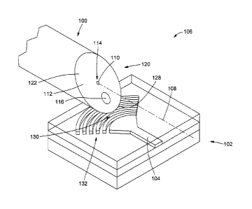
based systems and
devices, and more particularly, to techniques for enabling lateral coupling of
light between an
optical fiber and another optical device, for example an integrated photonics
device, or a probed
region.
[0005] In accordance with an aspect, there is provided an optical fiber for
lateral optical coupling.
The optical fiber includes a cladding; a core disposed in the cladding to
form; a reflecting structure
inclined relative to the fiber axis and configured to reflect light between
the core and a lateral
coupling path extending and providing lateral coupling of light between the
core and an exterior
of the optical fiber; and .a light-converging structure embedded in the
cladding to intercept and
convergeS light traveling along the lateral coupling path.
[0006] The lateral coupling path can provide either unidirectional or
bidirectional coupling. In
unidirectional applications, light can be coupled into the lateral coupling
path either from the core
to the exterior of the fiber or from the exterior of the fiber to the core,
but not both, while in
bidirectional applications, light can be coupled into the lateral coupling
path in both directions.
Thus, depending on the application or use, the optical fiber can provide any
or all of the following
types of lateral optical coupling: unidirectional coupling of light from the
core to the exterior of the
fiber, where the reflecting structure is configured to reflect light
propagating in the core out of the
core and into the lateral coupling path for coupling out of the optical fiber
and delivery to another
optical device or a region of interest; unidirectional coupling of light from
the exterior of the fiber,
for example from another optical device or a region of interest, to the core,
where the reflecting
structure is configured to reflect in-coupled light traveling along the
lateral coupling path out of the
lateral coupling path and into the core as guided light for propagation
therein; and bidirectional
coupling of light between the core and the exterior of the fiber.
[0007] In some implementations, the optical fiber has an angled end that
includes or forms the
reflecting structure However, in other implementations, the reflecting
structure may be provided
at an intermediate location along the optical fiber, rather than at an end
thereof. For example, the
optical fiber can have a cavity extending laterally through the cladding and
inside the core, such
that the cavity includes or forms the reflecting structure. Depending on the
application, the
reflecting structure may operate by total internal reflection inside the core
or be provided as a
reflecting layer formed on the core. For example, the reflecting layer can
include a metallic or a
dielectric coating deposited on the angled end of the core or on a portion of
the cavity. In other
CA 3023878 2018-11-13
3
implementations, the reflecting structure can include a tilted fiber Bragg
grating disposed in the
core and having its grating axis tilted with respect to the fiber axis.
[0008] In some implementations, the optical fiber can be used in optical
probing applications, for
example as the tip of an optical probe such as a fiber endoscope. In some of
these
implementations, the cladding can include a first cladding layer surrounding
the core and a second
cladding layer surrounding the first cladding layer. In such a case, the
reflecting structure can be
configured to reflect guided core light out of the core and into the lateral
coupling path for delivery
to a probed region outside the optical fiber and to reflect light collected
from the probed region
from the lateral coupling path to the first cladding layer for guided
propagation thereinside as
guided cladding light. In such implementations, the guided core light to be
delivered to the probed
region and the guided cladding light collected from the probed region
propagate in opposite
directions inside the optical fiber.
[0009] The cladding-embedded light-converging structure is configured to
receive or intercept
light rays propagating along the lateral coupling path and to make the light
rays at least less
diverging after passage of the light rays therein. Thus, the light-converging
structure is configured
such that converging input rays become more converging, parallel input rays
become converging
rays, and diverging input rays become less diverging, parallel (e.g., planar
wavefront) or
converging. The light-converging structure can produce an output signal of
reduced footprint size
and increased irradiance. By reducing the angular spread of the irradiance
distribution of the
laterally coupled light exiting the lateral coupling path, the provision of
the light-converging
structure can enhance the coupling efficiency of light into or out of the
optical fiber.
[0010] Depending on the application, the cladding-embedded light-converging
structure can have
various shapes, geometrical dimensions, material compositions, refractive
indices, spatial
arrangements and orientations, numbers of separate individual parts, and the
like. In some
implementations, the light-converging structure can include one or more rod
insertions embedded
in and extending longitudinally along the entire length of the cladding. For
example, the one or
more longitudinally extending rod insertions can consist of a single
longitudinally extending rod
insertion or multiple rod insertions radially distributed along the lateral
coupling path. However, in
other implementations, the light-converging structure can have a longitudinal
dimension that is
less than a length of the cladding.
[0011] In some implementations, the light-converging structure can include an
inward-facing
surface and an outward-facing surface located respectively closer to and
farther from the fiber
CA 3023878 2018-11-13
4
core. Each surface can be characterized by its curvature, which may be convex,
concave, flat or
a combination thereof, when viewed from the outside of the light-converging
structure. Depending
on the application, the light-converging structure can be made of a material
having either a
refractive index higher or lower than the refractive index of the surrounding
cladding. The sign of
.. the refractive index difference between the light-converging structure and
the cladding may
determine the type of surface curvature of the light-converging structure. In
some
implementations, the light-converging structure can have an overall convex
shape when its
refractive index is higher than that of the cladding and an overall concave
shape when its
refractive index is lower than that of the cladding. In general, various
combinations of refractive
index differences and surface shapes can be envisioned within the scope of the
present
disclosure.
[0012] In some implementations, the light-converging structure comprises an
antireflection
coating formed on at least part of an outer surface thereof in contact with
the cladding to prevent
or reduce unwanted or detrimental interface reflections caused by the
refractive index mismatch
between the light-converging structure and cladding. In some implementations,
the light-
converging structure can be a hole or cavity formed in the cladding. The hole
or cavity can be
filled with air or another material.
[0013] In some implementations, the light-converging structure can include a
refractive
converging element configured to receive and focus light traveling along the
lateral coupling path.
In some scenarios, the refractive converging element can include a piano-
convex, a biconvex or
a positive meniscus cylindrical lens element made of a material having a
refractive index higher
than a refractive index of the cladding. In other scenarios, the refractive
converging element can
include a plano-concave, a biconcave or a negative meniscus cylindrical lens
element made of a
material having a refractive index lower than a refractive index of the
cladding. In some
implementations, the refractive converging element can act as a cylindrical
lens configured to
focus an incoming irradiance distribution predominantly along one dimension to
produce a beam
having an anisotropic irradiance distribution. For example, such an
anisotropic beam can include
a beam having an elliptically shaped irradiance profile or high astigmatism,
or in the limiting case,
a beam focused to a line.
.. [0014] In some implementations, the light-converging structure can include
a waveguiding
element configured to confine and guide light therein along a waveguiding path
forming at least
part of the lateral coupling path between the core and exterior of the optical
fiber. For example,
CA 3023878 2018-11-13
5
the waveguiding element can be a slab waveguide made of material having a
refractive index
higher than a refractive index of the cladding and extending widthwise along
the lateral coupling
path and lengthwise along the fiber axis.
[0015] In some implementations, the presence of the cladding-embedded light-
converging
structure does not adversely disturb or affect propagation of guided light in
the core, notably in
the fundamental mode. In such implementations, the physical separation and/or
refractive index
difference between the core and the light-converging structure can be designed
or engineered to
avoid or at least mitigate such unwanted or adverse perturbations.
[0016] In some implementations, the optical fiber includes an angled end that
includes or forms
.. the reflecting structure and a fiber-coupling end opposite the angled end
and configured for
coupling the optical fiber to a main optical fiber. In such implementations,
the optical fiber operates
as a fiber-optic transition coupler for coupling light between the main
optical fiber, via the fiber-
coupling end, and an optical device or a probed region, via the lateral
coupling path at the angled
end. The fiber-optic transition coupler can provide a more efficient coupling
of light to and/or from
the main optical fiber. In some implementations, the optical fiber operating
as a fiber-optic
transition coupler can be a relatively short fiber segment, for example having
a fiber length ranging
from about 0.1 centimeter (cm) to about 100 cm. In some implementations, the
optical device can
be a planar optical waveguide provided on a photonic integrated optical
circuit or chip. In other
implementations, the optical device can be an optical source, for example an
edge-emitting laser
diode. In yet other implementations, the fiber-optic transition coupler can be
used in an optical
probe, for example as the distal tip of a fiber endoscope configured for
delivery of probing light to
a target region, with or without signal collection.
[0017] In accordance with another aspect, there is provided a coupled optical
system including
an optical device and an optical fiber optically coupled to the optical
device. The optical fiber
includes a cladding; a core disposed in the cladding; a reflecting structure
configured to reflect
light between the core and a lateral coupling path extending in the cladding
between the core and
an exterior of the optical fiber to provide lateral optical coupling between
the core and the optical
device; and a light-converging structure embedded in the cladding to intercept
and converge light
traveling along the lateral coupling path.
[0018] In some implementations, the optical device can be a photonic
integrated circuit
comprising a planar optical waveguide, for example a grating-coupled waveguide
or an edge-
coupled waveguide. In other implementations, the optical device can be an
optical source
CA 3023878 2018-11-13
6
configured to emit a source optical signal and the optical fiber is configured
to collect the source
optical signal via the lateral coupling path for coupling the source optical
signal as guided light
into the core. For example, the optical source can be an edge-emitting laser
diode.
[0019] In some implementations, the coupled optical system can include a
support structure
configured to support the optical fiber. For example, the support structure
can be a V-groove
support structure including a V-groove configured to receive the optical
fiber. In some
implementations, the optical fiber is one of a plurality of optical fibers
coupled to the optical device.
For example, the optical device can be a photonic integrated circuit including
a plurality of planar
optical waveguides, each of which optically coupled to a corresponding one of
the optical fibers.
In such a case, the V-groove support structure can include a plurality of V-
grooves, each of which
to receive a corresponding one of the optical fibers in a parallel, side-by-
side and spaced-apart
relationship. The provision of the V-groove support structure can ensure or
facilitate positioning
and alignment of the optical fibers for coupling to the optical device. In
some implementations, a
lid cover can be provided over the optical fibers received in the V-groove
support structure, the
lid cover being interposed between the optical fibers and the optical fibers
and being traversed by
light coupled therebetween.
[0020] In some implementations, the coupled optical system can include a
support structure
configured to support the optical fiber. For example, the support structure
can be a V-groove
support structure include a V-groove configured to receive the optical fiber.
In some
implementations, the optical fiber is one a plurality of optical fibers
coupled to the optical device.
For example, the optical device can be a photonic integrated circuit including
a plurality of planar
optical waveguides, each of which optically coupled to a corresponding one of
the optical fibers.
In such a case, the V-groove support structure can include a plurality of V-
grooves, each of which
to receive a corresponding one of the optical fibers in a parallel, side-by-
side and spaced-apart
relationship. The provision of the V-groove support structure can ensure or
facilitate positioning
and alignment of the optical fibers for coupling to the optical device. In
some implementations, a
lid cover can be provided over the optical fibers received in the V-groove
support structure, the
lid cover being interposed between the optical fibers and the optical fibers
and being traversed by
light coupled therebetween.
[0021] In accordance with another aspect, there is provided a fiber-optic
transition coupler or
device for optical coupling between a main optical fiber and another optical
device or a probed
region. The fiber-optic transition coupler includes fiber-coupling end
configured for coupling to the
CA 3023878 2018-11-13
7
main optical fiber and an angled end opposite the fiber-coupling end. The
fiber-optic transition
coupler also includes a cladding, a core disposed in the cladding, a
reflecting surface extending
on the angled end, and a light-converging structure embedded in the cladding.
The reflecting
surface is configured to reflect light between the core and the light-
converging structure is
configured to intercept and converge light traveling along the lateral
coupling path.
[0022] In accordance with another aspect, there is provided a method for
fabricating an optical
fiber having a cladding, a core, a reflecting structure, and a cladding-
embedded light-converging
structure, such as disclosed herein.
[0022a] In accordance with another aspect, there is provided an optical fiber
for lateral optical
coupling, comprising:
a cladding;
a core disposed in the cladding;
a reflecting structure inclined relative to the fiber axis and configured to
reflect light between
the core and a lateral coupling path extending and providing lateral coupling
of light
between the core and an exterior of the optical fiber; and
a light-converging structure embedded in the cladding to intercept and
converge light traveling
along the lateral coupling path, wherein the light-converging structure
comprises one or
more longitudinally extending rod insertions.
[0022b] In accordance with another aspect, there is provided a coupled optical
system
comprising:
an optical device; and
an optical fiber optically coupled to the optical device, the optical fiber
comprising:
a cladding;
a core disposed in the cladding;
a reflecting surface configured to reflect light between the core and a
lateral coupling
path extending in the cladding between the core and an exterior of the optical
fiber
to provide lateral optical coupling between the core and the optical device;
and
a light-converging structure embedded in the cladding to intercept and
converge light
traveling along the lateral coupling path, wherein the light-converging
structure
comprises one or more longitudinally extending rod insertions.
Date Recue/Date Received 2021-10-05
7a
[0023] It is to be noted that other method and process steps may be performed
prior, during or
after the steps described herein. The order of one or more steps may also
differ, and some of the
steps may be omitted, repeated and/or combined, depending on the application.
[0024] Other features and advantages of the present description will become
more apparent upon
reading of the following non-restrictive description of specific embodiments
thereof, given by way
of example only with reference to the appended drawings. Although specific
features described
in the above summary and in the detailed description below may be described
with respect to
specific embodiments or aspects, it should be noted that these specific
features can be combined
with one another unless stated otherwise.
BRIEF DESCRIPTION OF THE DRAWINGS
[0025] Figs. 1A to 1C are schematic perspective, side and front views,
respectively, of a coupled
optical system including an optical fiber coupled to a planar optical
waveguide, in accordance with
a possible embodiment.
[0026] Fig. 2 is a schematic side view of a coupled optical system including
an optical fiber
coupled to a planar optical waveguide, in accordance with another possible
embodiment.
[0027] Figs. 3A and 3B are schematic side views of a coupled optical system
including an optical
fiber coupled to a planar optical waveguide, in accordance with two other
possible embodiments
in which the reflecting structure is provided, and lateral optical coupling
occurs, at an intermediate
location along the length of the optical fiber.
[0028] Fig. 4 is a schematic side view of a coupled optical system including
an optical fiber
coupled to a planar optical waveguide, in accordance with another possible
embodiment.
Date Recue/Date Received 2021-10-05
8
[0029] Figs. 5A and 5B are respectively schematic side and front views of a
conventional lateral
fiber coupling arrangement using an optical fiber to couple light into and out
of a grating-coupled
planar optical waveguide.
[0030] Fig. 6 is a schematic side view of a coupled optical system including
an optical fiber
coupled to a planar optical waveguide, in accordance with another possible
embodiment.
[0031] Figs. 7A to 7F are schematic front views of other possible embodiments
of a coupled
optical system including an optical fiber coupled to a planar optical
waveguide. In each
embodiment, the cladding-embedded light-converging structure includes a
refractive converging
element having a different transverse cross-sectional shape
[0032] Figs. 8A to 8H are schematic representations of example steps of a
fabrication method of
an optical fiber including a cladding-embedded light-converging structure, in
accordance with
another possible embodiment.
[0033] Figs. 9A and 9B are respectively schematic side and front views of an
optical fiber, in
accordance with another possible embodiment. The optical fiber includes a
cladding-embedded
light-converging structure embodied by a graded-index (GRIN) lens rod.
[0034] Figs. 10A and 10B are respectively schematic side and front views of an
optical fiber, in
accordance with another possible embodiment. The optical fiber includes a
cladding-embedded
light-converging structure including a pair of longitudinally extending rod
insertions distributed
along the lateral coupling path.
[0035] Figs. 11A to 11D are schematic cross-sectional front views of four
other possible
embodiments of an optical fiber including a cladding-embedded light-converging
structure and at
least one other off-centered structure.
[0036] Figs. 12A and 126 are respectively schematic side and front views of an
optical fiber, in
accordance with another possible embodiment. The optical fiber includes a
cladding-embedded
light-converging structure having an elliptical cross-section. Figs. 12C to
12F schematically depict
an example of process steps for fabricating a final preform that can be drawn
into the optical fiber
of Figs. 12A and 12B.
[0037] Figs. 13A and 13B are respectively schematic side and front views of an
optical fiber, in
accordance with another possible embodiment. The optical fiber includes a
cladding-embedded
CA 3023878 2018-11-13
9
light-converging structure having an antireflection coating thereon. Figs. 13C
to 13F schematically
depict an example of process steps for fabricating a final preform ready for
drawing into the optical
fiber of Figs. 13A and 13B.
[0038] Figs. 14A and 14B are respectively schematic side and front views of an
optical fiber, in
accordance with another possible embodiment. The optical fiber includes a
concave-shaped light-
converging structure made of a material having a refractive index lower than
the refractive index
of the cladding. Fig. 14C schematically depicts an example of process steps
for fabricating a final
preform ready for drawing into the optical fiber of Figs. 14A and 14B.
[0039] Figs. 15A and 15B are respectively schematic side and front views of an
optical fiber, in
accordance with another possible embodiment. The optical fiber includes a
cladding-embedded
light-converging structure configured to function as a two-dimensional slab
waveguide within
which light coupled into the lateral coupling path is to be confined and
guided. Figs. 15C and 15D
are schematic front views of an optical fiber, in accordance with other
possible embodiments,
wherein the light-converging structure is a two-dimensional slab waveguiding
tapering radially
toward (Fig. 15C) and away (Fig. 15D) from the fiber axis. Fig. 15E
schematically depicts an
example of process steps for fabricating a final preform ready for drawing
into the optical fiber of
Figs. 15A and 15B.
[0040] Figs. 16A and 16B are respectively schematic side and front views of an
optical fiber, in
accordance with another possible embodiment, in which the optical fiber
includes structural
modifications to its outer lateral surface.
[0041] Figs. 17A and 17B are respectively schematic perspective and front
views of an array of
optical fibers, in accordance with an embodiment, in which the optical fibers
are received and held
in a V-groove support structure.
[0042] Figs. 18A and 18B are respectively schematic perspective and front
views of an array of
optical fibers, in accordance with another embodiment. in which the optical
fibers are hosted in a
common, rectangular prismatic cladding having an angled endface.
[0043] Fig. 19 is a schematic side view of a fiber-optic transition coupled
between a main optical
fiber and a grating-coupled planar optical waveguide, in accordance with a
possible embodiment.
[0044] Figs. 20A to 20D are schematic representations of an example of process
steps for
assembling a coupled optical system in which a main optical fiber is coupled
to a grating-coupled
CA 3023878 2018-11-13
10
planar optical waveguide via a transition optical fiber including an angled
end and a cladding-
embedded light-converging structure. Fig. 20E is a variant in which the
transition optical fiber and
the main optical fiber are connected to each other by mechanical fiber
connectors.
[0045] Fig. 21 is a table that includes computer simulation parameters and
results representing
the lateral coupling efficiency of three embodiments compared to a
conventional angled-fiber-
based lateral coupling technique.
[0046] Figs. 22A to 22C are respectively schematic perspective, side and front
views of an optical
fiber, in accordance with another possible embodiment, in which the optical
fiber is used in a laser
diode coupling application. Fig. 22D is a variant in which an antireflection
coating is provided over
a portion of the outer lateral surface of the fiber facing the laser diode.
[0047] Figs. 23A to 23C are respectively schematic perspective, side and front
views of an optical
fiber, in accordance with another possible embodiment, in which the optical
fiber is used for edge
coupling with a planar optical waveguide. In Fig. 23B, the arrow indicates the
direction along
which the optical fiber is pushed until it abuts against a stop wall of a V-
groove receiving the
optical fiber. In Fig. 23C, the arrow indicates the rotational degree of
freedom to allow adjustment
of the optical fiber with respect to the planar optical waveguide and to
control the optical coupling
efficiency therebetween.
[0048] Figs. 24A and 24B are respectively schematic side and front views of an
optical fiber, in
accordance with another possible embodiment, in which the optical fiber is
implemented in the
distal tip of a fiber probe or endoscope for probing a target of interest.
DETAILED DESCRIPTION
[0049] In the present description, similar features in the drawings have been
given similar
reference numerals. To avoid cluttering certain figures, some elements may not
be indicated, if
they were already identified in a preceding figure. It should also be
understood that the elements
of the drawings are not necessarily depicted to scale, since emphasis is
placed on clearly
illustrating the elements and structures of the present embodiments.
Furthermore, positional
descriptors indicating the location and/or orientation of one element with
respect to another
element are used herein for ease and clarity of description. Unless otherwise
indicated, these
positional descriptors should be taken in the context of the figures and
should not be considered
limiting. More particularly, it will be understood that such spatially
relative terms are intended to
CA 3023878 2018-11-13
11
encompass different orientations in the use or operation of the present
embodiments, in addition
to the orientations exemplified in the figures.
[0050] Unless stated otherwise, the terms "connected", "coupled", and
derivatives and variants
thereof, refer to any connection or coupling, either direct or indirect,
between two or more
elements. The connection or coupling between the elements may be mechanical,
optical,
electrical, magnetic, logical, or a combination thereof.
[0051] In the present description, the terms "a", "an" and "one" are defined
to mean "at least one",
that is, these terms do not exclude a plural number of items, unless stated
otherwise.
[0052] Terms such as "substantially", "generally" and "about", that modify a
value, condition or
characteristic of a feature of an exemplary embodiment, should be understood
to mean that the
value, condition or characteristic is defined within tolerances that are
acceptable for proper
operation of this exemplary embodiment for its intended application.
[0053] The present description generally relates to optical coupling in fiber-
based systems and
devices. In accordance with various non-limiting aspects, the present
description discloses an
optical fiber for lateral optical coupling; a coupled optical system including
an optical fiber and an
optical device coupled thereto; a fiber-optic transition coupler for optical
coupling between a main
optical fiber and another optical device or a probed region; and a method for
fabricating an optical
fiber such as disclosed herein.
[0054] The present techniques can be used in various applications where it is
desirable or
required to provide coupling of light between an optical fiber and another
optical device or a
probed region. More particularly, the present techniques can be implemented in
a variety of fiber-
based light delivery and/or collection systems for use in fields such as, for
example, integrated
photonics, biophotonics, telecommunications, sensing, and spectroscopy. Non-
limiting examples
of possible applications include: light delivery to and/or light collection
from an integrated optical
device, for example a photonic integrated chip or a semiconductor laser; and
delivery of probing
light to a target using fiber endoscopes, fiber probes and fiber-based medical
probes, with or
without signal collection from the target. For example, fiber probes without
signal collection can
be used in phototherapy applications.
[0055] In the present description, the terms "light" and "optical", and
derivatives and variants
thereof, are used to refer to radiation in any appropriate region of the
electromagnetic spectrum.
These terms are not limited to visible light but can also include invisible
regions of the
CA 3023878 2018-11-13
12
electromagnetic spectrum including, but not limited to, the infrared
wavelength range. For
example, in non-limiting embodiments, the present techniques can be
implemented with light
having a wavelength band lying somewhere in the range from about 400
nanometers (nm) to
about 1800 nm. However, this range is provided for illustrative purposes only
and the present
techniques may operate outside this range.
[0056] The terms "longitudinal", "axial", and derivatives and variants
thereof, refer herein to a
direction that is parallel or substantially parallel to the length or the
fiber axis of the optical fiber
from or to which light is coupled. Meanwhile, the terms "transverse",
"lateral", "radial", and
derivatives and variants thereof, refer to a direction that lies in a plane
perpendicular or
substantially perpendicular to the length or the fiber axis of the optical
fiber, and therefore to the
longitudinal or axial direction as just defined.
[0057] In the present description, the term "probed region" is to be
interpreted broadly to
encompass any object, structure, substance, material, person or other living
organism,
environment, medium or region of space to which light can be transmitted
and/or from which light
can be received. Furthermore, the term "fiber probe" and "fiber-based optical
probe", and
derivatives and variants thereof, are intended to refer to any fiber-based
optical system or device
which can deliver optical energy to a region of interest and/or collect
optical energy from the region
of interest. That is, these terms are meant to encompass optical systems and
devices used solely
for light delivery, optical systems and devices used solely for light
collection, and optical systems
and devices used for both light delivery and light collection.
[0058] Various implementations of the present techniques will now be described
with reference
to the figures.
[0059] Figs. 1A to 1C are schematic perspective, side and front views,
respectively, of a possible
embodiment of an optical fiber 100 for use in lateral coupling of light to
and/or from another optical
.. device. In this embodiment, the other optical device is a grating-coupled
planar optical
waveguide 102 including a waveguiding path 104 along which light can be
guided. In this
embodiment, the optical fiber 100 is disposed over and parallel to the planar
optical
waveguide 102, either in direct or indirect contact therewith. The optical
fiber 100 and the planar
optical waveguide 102 together form a coupled optical system 106.
.. [0060] The planar optical waveguide 102 may be part of a photonic
integrated circuit, for example
based on silicon-on-insulator (S01) technology and be embodied by any
appropriate type of planar
CA 3023878 2018-11-13
13
waveguide structure including, but not limited to, a slab waveguide, a strip
waveguide, a ridge
waveguide and a rib waveguide. The planar optical waveguide 102 may include a
plurality of
layers stacked on a substrate, at least one of these defining the waveguiding
path 104. It should
be noted, however, that the optical device depicted in Figs. 1A to 1C is
provided for illustrative
purposes only, and that other embodiments can use various other types of
optical devices for
coupling to an optical fiber such as disclosed herein.
[0061] In Figs. 1A to 1C, the optical fiber 100 extends along a longitudinal
fiber axis 108 and
includes a core 110, a cladding 112 surrounding the core 110, a reflecting
structure 114 inclined
relative to the fiber axis 108, and a light-converging structure 116 embedded
in the cladding 112.
The structure, configuration and operation of these and other possible
components of the optical
fiber 100 will be described in greater detail below.
[0062] The core 110 is disposed in the cladding 112 to form a light-guiding
path 118 along which
light can be guided. Depending on the application, the core 110 may or may not
be parallel to the
waveguiding path 104 of the planar optical waveguide 102. The core 110 is made
of a core
.. material having a refractive index higher than the refractive index of the
cladding material so that
light can be guided therealong by total internal reflection at the interface
between the core 110
and the cladding 112. The optical fiber 100 can have various cladding and core
compositions and
refractive index profiles (e.g., graded-index profile or step-index profile).
For example, in some
embodiments, the cladding 112 can be made of pure silica and the core 110 can
be made of silica
.. containing one or more index-changing dopants. In other embodiments, other
suitable materials
can be used for the cladding 112 and the core 110 (e.g., plastic, sapphire, or
composite glasses).
Depending on the application, the core 110 may be either single mode or
multimode and may
support different polarization states. In Figs. 1A to 1C, the core 110 has a
circular cross-section
and is centered on the fiber axis 108, and the cladding 112 has a single-layer
structure and a
circular outer contour. However, in other embodiments, a non-circular and/or
off-centered cores
and non-circular and/or multilayer (e.g., a double-clad or triple-clad)
claddings may be used. In
some non-limiting embodiments, the core 110 can have a diameter ranging from
about 4 pm to
about 80 pm and the cladding can have a diameter ranging from about 80 pm to
about 500 pm.
Other core and cladding sizes can be used in other embodiments. It should be
noted that, in
general, the composition, cross-sectional shape and size, refractive index
profile, number of
cores, number of guided modes, passive or active operation mode, operating
wavelength range,
polarization-maintaining (PM) properties and other core properties may be
varied in accordance
with a specified application.
CA 3023878 2018-11-13
14
[0063] In Figs. 1A to 1C, the optical fiber 100 terminates into an angled end
or tip 120 defining a
cleaved or angled endface 122. The angled end 120 includes or forms the
reflecting
structure 114. Depending on the application, the angled end 120 may be formed
by polishing,
grinding, etching, cleaving, machining or by any other suitable technique or
combination of such
techniques. For example, the angled end 120 may be made by an individual setup
having visual
recognition capabilities to ensure or help ensure that the resulting angled
endface 122 is
sufficiently flat and has a controlled orientation.
[0064] The reflecting surface provided by the reflecting structure 114 can be
substantially flat,
although non-flat geometries can also be used in some applications. In some
implementations,
light can be reflected off the reflecting structure 114 by total internal
reflection inside the core 110
for incidence angles exceeding the critical angle. Referring to Fig. 2, in
another embodiment, a
light-reflecting layer 124 may be deposited on the angled endface 122 to
provide the reflecting
structure 114. Depending on the application, the light-reflecting layer 124
can be a metallic
coating (e.g., gold, silver or aluminum) or a dielectric coating. The metallic
or dielectric coating
can be deposited on the angled endface using various deposition techniques.
[0065] Referring to Figs. 3A and 3B, in other variants, the reflecting
structure 114 may
alternatively be provided at an intermediate location between the two ends of
the optical fiber 100,
rather than at one of the ends. In Fig. 3A, the optical fiber 110 includes a
cavity 212 formed by
removing part of the cladding 112 and the core 110, for example by laser
ablation, etching or
mechanical processing. The cavity 212 extends through the cladding 112 and
into the core 110
to form or include the reflecting structure 114. Depending on the application,
the reflecting
structure 114 formed by or provided in the cavity 212 may operate by total
internal reflection inside
the core 110 at the core-cavity interface or be provided as a reflecting layer
formed at the core-
cavity interface. In Fig. 38, the reflecting structure 114 includes a tilted
fiber Bragg grating 214
disposed in the core 110 with its grating axis 216 oriented at a tilt angle
with respect to the fiber
axis 108. For example, the tilted fiber Bragg grating 214 can be inscribed in
the core 110 by
conventional laser processing techniques. Depending on the application, the
tilted fiber Bragg
grating 214 can reflect all or only a portion of the guided core light
incident thereon. Of course, in
other implementations, the reflecting structure can be embodied by various
optical elements or
combinations of optical elements which can deflect, at least partly, the
optical path of light incident
thereonto. The optical elements forming the reflecting structure can include
reflecting, refractive
or diffracting optical elements, or a combination thereof.
CA 3023878 2018-11-13
15
[0066] Returning to Figs. 1A to 1C, the orientation of the reflecting
structure 114 can be described
by an inclination angle 0 defined between the normal N to a reflecting surface
defined by the
reflecting structure 114 and the longitudinal fiber axis 108. In some
embodiments, the inclination
angle 0 can range from about 300 to about 650, although other values can be
used in other
embodiments. The orientation of the reflecting structure 114 may be selected
so that the reflecting
structure 114 reflects light incident thereon between the core 110 and a
lateral coupling path 126
extending between the reflecting structure 114 and an outer lateral surface
128 of the fiber 100.
The lateral coupling path 126 enables lateral coupling of light from the core
110 and toward an
exterior 130 of the optical fiber 100 and/or from the exterior 130 to the core
110 of the optical
fiber 100. Thus, the reflecting structure 114 can be oriented such that the
orientation of the lateral
coupling path 126 relative to the planar optical waveguide 102 optimizes or
favors optical coupling
between it and the optical fiber 100. For example, when the planar optical
waveguide 102 is
coupled to the optical fiber 100 by a vertical grating coupler (see below),
the orientation of the
reflecting structure can be selected such that the lateral coupling path 126
be tilted at an angle of
between about -30 and about +30 with respect to a vertical axis
perpendicular to the surface of
the waveguide 102.
[0067] In the present description, the term "lateral coupling path" generally
refers to a region of
the optical fiber 100 along which light can travel or be coupled laterally
between the core 110 and
a location 130 outside of the fiber 100. Depending on the application, the
lateral coupling path 126
.. can provide unidirectional lateral coupling, in either direction, or
bidirectional coupling. That is, the
lateral coupling path 126 can allow light to be coupled from the core 110 to
the exterior 130 of the
fiber 100, or vice versa, or both. Thus, depending on the application or use,
the optical fiber 100
can provide any or all of the following types of lateral optical coupling:
unidirectional coupling of
light from the core 110 to the fiber exterior 130, where the reflecting
structure 114 is configured
.. to reflect light propagating in the core 110 along the light-guiding path
118 out of the core 110 and
into the lateral coupling path 126 for coupling out of the optical fiber 100
and delivery to another
optical device 102 or a region of interest; unidirectional coupling of light
from the fiber exterior 130,
for example from another optical device 102 or a region of interest, to the
core 110, where the
reflecting structure 114 is configured to reflect in-coupled light traveling
along the lateral coupling
path 126 out of the lateral coupling path 126 and into the core 110 as guided
light for propagation
therein; and bidirectional coupling of light between the core 110 and the
exterior 130 of the
fiber 100.
CA 3023878 2018-11-13
16
[0068] It should be noted that the term "lateral" when referring to the
lateral coupling path 126 is
intended to refer to the fact that the coupling of light between the core 110
and the exterior 130
of the fiber 100 occurs through the outer lateral surface 128 of the fiber
100, rather than, for
example, through an endface. It should also be noted that the lateral coupling
path 126 need not
be strictly perpendicular to the fiber axis 108, but may have a certain
longitudinal extent, as
mentioned above and depicted in Fig. 1B. Thus, depending on the angle 0
between the fiber
axis 108 and the reflecting plane defined by the reflecting structure 114, the
longitudinal
component of the wave vector of light may or may not change sign after
reflection from the
reflecting structure 114. This means that the direction of light propagation
in the optical fiber 100
may be parallel ¨ as depicted in Fig. 1B ¨ or antiparallel ¨ as in Fig. 4 ¨ to
the direction of light
propagation in the planar optical waveguide 102.
[0069] Referring still to Figs. 1A to 1C, the optical fiber 100 extends over
the planar optical
waveguide 102 with the angled end 120 positioned such that at least part of
the light coupled in
and/or out of the fiber 100 via the lateral coupling path 126 is coupled in
and/or out of the planar
optical waveguide 102 by an optical waveguide coupler 132 disposed in the
planar optical
waveguide 102. In the present description, the term "optical waveguide
coupler" refers broadly to
an optical component configured to couple light between the optical fiber 100
and the planar
optical waveguide 102, either unidirectionally, in either direction, or
bidirectionally. In some
implementations, the optical waveguide coupler 132 can be an optical grating
structure including
one or more diffraction gratings. The term "diffraction grating" generally
refers herein to a structure
having periodic optical properties (e.g., a refractive index profile defined
by alternating grooves
and ridges) that spatially modulates the amplitude and/or phase of an optical
wavefront incident
thereon. For example, in the illustrated embodiment, the optical waveguide
coupler 132 is a
vertical grating coupler disposed along the waveguding path 104 of the planar
optical
waveguide 102 and configured to receive light from and/or direct light into
the optical fiber 100 via
the lateral coupling path 126. The general principles underlying the structure
and operation of
diffraction grating couplers are known in the art and need not be covered in
detail herein. It should
be noted, however, that the present techniques are not limited by the type and
location of the
optical waveguide coupler within the planar optical waveguide and that various
coupling
arrangements can be envisioned. For example, in some implementations, a
polarization splitting
grating coupler could be used.
[0070] The optical fiber 100 also includes a light-converging structure 116
embedded or disposed
in the cladding 112, so as to cross the lateral coupling path 126. The light-
converging
CA 3023878 2018-11-13
17
structure 116 is configured to intercept and converge laterally light incident
thereon and escaping
from the core 110 (i.e., out-coupled light) and/or from the exterior 130 of
the fiber 100 (i.e., in-
cou pled light).
[0071] In the present description, the term "light-converging structure"
refers broadly to an optical
structure configured to receive light rays propagating along the lateral
coupling path and to reduce
the divergence of the light rays after their passage therein or therethrough.
The light-converging
structure 116 of Figs. 1A to 1C produces an output beam of reduced footprint
and increased
irradiance. In some implementations, the light-converging structure acts as a
cylindrical lens that
focuses the wavefront of the incident light predominantly along a single
dimension to produce a
beam having a nonsymmetric irradiance distribution, for example, a beam having
an elliptically
shaped irradiance profile or high astigmatism, or in the limiting case, a beam
focused along a line.
That is, the light-converging structure focuses light in the direction
perpendicular to the fiber axis,
without substantially changing light along the fiber axis.
[0072] Depending on the application, the light-converging structure 116 can
include a single part
or structural element embedded, incorporated or otherwise disposed in the
cladding 112 along
the lateral coupling path 126, or a plurality of parts or structural elements
disposed at discrete,
spaced-apart locations along the lateral coupling path 126. In the latter
case, the multiple parts of
the light-converging structure 116 are, overall, optically converging,
although each individual part
may be either converging, diverging or neutral. The light-converging structure
116 can act as a
refractive structure or a waveguiding structure, as described in greater
detail below, although
reflective and diffractive structures could also be used.
[0073] Referring to Figs. 5A and 5B, there is shown a conventional coupling
arrangement using
an optical fiber 100' to couple light into and out of a grating-coupled planar
optical waveguide 102'.
The optical fiber 100' has a fiber axis 108' and is cleaved at an angle to
form an angled end 120'.
The angled end 120' acts as a reflecting structure 114' that reflects guided
light propagating in
the core 110' into a lateral coupling path 126' that extends through the
cladding 112' and causes
the reflected light to be coupled out of the fiber 100' and into an optical
waveguide coupler 132'.
The optical waveguide coupler 132' couples the received light into the planar
optical
waveguide 102' for propagation therealong. Light can also propagate in the
opposite direction,
from the planar optical waveguide 102', through the optical waveguide coupler
132' and the lateral
coupling path 126', and into the core 110' after reflection off the reflecting
structure 114'. Unlike
the embodiment of Figs. 1A to 1C, the optical fiber 100' in Figs. 5A and 5B
does not include a
CA 3023878 2018-11-13
18
light-converging structure disposed along the lateral coupling path 126'.
While the conventional
fiber coupling technique depicted in Figs. 5A and 5B may have certain
advantages, it also has
some drawbacks and limitations. One drawback is that the reflecting structure
114' reflects light
incident thereon as a diverging beam of light, which can cause mode size
mismatch between the
optical fiber 100' and the planar optical waveguide 102' and, in turn,
increased coupling losses.
[0074] Returning to Figs. 1A to 1C, the provision of a light-converging
structure 116 along the
lateral coupling path 126 can enhance the efficiency of light coupling between
the optical fiber 100
and the planar optical waveguide 102 by reducing the angular spread of the
irradiance distribution
of the laterally coupled light exiting the lateral coupling path 126, relative
to when the light-
converging structure 116 is absent. In some implementations, the light-
converging structure 116
can be used to modify, shape or otherwise act on the wavefront of laterally
coupled light
propagating along the lateral coupling path 126 before it reaches the optical
waveguide
coupler 132 (for laterally out-coupled light) or the reflecting structure 114
(for laterally in-coupled
light) to reduce or help reduce mode size mismatch and coupling losses between
the optical
fiber 100 and the planar optical waveguide 102. Fig. 1C schematically
illustrates the converging
action of the light-converging structure 116 exerted on the light propagating
along the lateral
coupling path 126.
[0075] In some implementations, the light-converging structure 116 may be
configured to shape
or condition, to a certain extent, the optical wavefront of laterally out-
coupled light to match input
requirements or specifications of the optical waveguide coupler 132. It may
also be possible to
tailor or design the optical waveguide coupler 132 to match the laterally out-
coupled light
corresponding to a certain light-converging structure 116. Therefore, in some
implementations,
both the light-converging structure 116 and the optical waveguide coupler 132
may have
adjustable parameters allowing for coupling efficiency optimization and
tradeoff. In some
implementations, the light-converging structure 116 is located sufficiently
far from the core 110 to
avoid or help avoid unwanted or detrimental perturbations to the propagation
of light in the
core 110.
[0076] Depending on the application, the light-converging structure 116 can be
made in various
shapes, geometrical dimensions, material compositions, refractive indices,
spatial arrangements
and orientations, numbers of separate individual parts, and the like. It
should be noted that, in
some instances, the term "light-converging structure" can be used
interchangeably with the terms
"fiber cladding modification", shortened herein as "FCM", and "fiber cladding-
embedded
CA 3023878 2018-11-13
19
structure". In some embodiments, the light-converging structure 116 can
include one or more rod-
shaped elongated insertions embedded in the cladding 112 and extending
parallel or nearly
parallel to, but radially offset from, the fiber axis 108. For example, in
Figs. 1A to 1C, the light-
converging structure 116 is a cylindrical rod insertion. However, in other
embodiments, the light-
converging structure 116 may have a more limited longitudinal extent while
still being within the
lateral coupling path 126 to receive and converge at least a substantial or
specified portion of the
laterally coupled light propagating therealong, as shown in the embodiment of
Fig. 6, where the
light-converging structure 116 is shorter than the cladding 112.
[0077] Returning to Figs. 1A to 1C, the light-converging structure 116 can
include an inward-
facing surface 134 ¨ located closer to the core 110 of the optical fiber 100 ¨
and an outward-
facing surface 136 ¨ located closer to the outer lateral surface 128 of the
optical fiber 100. Each
of these surfaces 134, 136 can be characterized by its curvature, which may be
convex, concave,
flat, a combination thereof or have other geometries (e.g. parabolic,
acylindrical), when viewed
from the outside.
[0078] Depending on the application, the light-converging structure 116 can be
made of a
material having a refractive index higher, as in Figs. 1A to 1C, or lower than
the refractive index
of the cladding 112. In some implementations, whether the sign of the
refractive index difference
between the light-converging structure 116 and the cladding 112 can determine
the type of
surface curvature of the light-converging structure 116. For example, each one
of the inward-
facing surface 134 and outward-facing surface 136 of the light-converging
structure 116 can be
convex or concave, when viewed from the outside, depending on whether the
refractive index of
the light-converging structure 116 is higher or lower, respectively, than that
of the cladding 112.
In some implementations, the light-converging structure 116 can have an
overall convex shape
when its refractive index is higher than that of the cladding and an overall
concave shape when
its refractive index is lower than that of the cladding. For example, in Figs.
1A to 1C, the inward-
facing surface 134 and the outward-facing surface 136 of the light-converging
structure 116 are
convex half-cylindrical surfaces. Of course, various other combinations of
refractive index
differences and surface shapes are possible and intended to fall within the
scope of the present
disclosure.
[0079] Referring to Figs. 7A to 7F, there are illustrated six exemplary
embodiments of an optical
fiber 100 in which the light-converging structure 116 is a refractive
converging element or lens
configured to receive and focus light traveling along the lateral coupling
path 126. The transverse
CA 3023878 2018-11-13
20
cross-sectional shape of the refractive light-converging structure 116 is
different in each
embodiment. In Figs. 7A to 70, the light-converging structure 116 is made of a
material having a
refractive index higher than the refractive index of the cladding 110 and is
shaped as a piano-
convex (Fig. 7A), a biconvex (Fig. 7B) or a positive meniscus (Fig. 7C)
optical element or lens. In
Figs. 7D to 7F, the light-converging structure 116 is made of a material
having a refractive index
lower than the refractive index of the cladding 110 and is shaped as a piano-
concave (Fig. 7D), a
biconcave (Fig. 7E) or a negative meniscus (Fig. 7D) optical element or lens
made of a material
having a refractive index lower than a refractive index of the cladding. It is
noted that in Figs. 7A
to 7F, the light-converging structure 116 has no curvature along the
longitudinal direction,
perpendicular to the plane of the figures.
[0080] Figs. 8A to 8D are schematic representations of example steps of a
fabrication method of
a possible embodiment of an optical fiber 100 including a light-converging
structure 116
embedded in the cladding 112. The method usually starts with a step of
providing a mother
preform 138 having a core 110 and a cladding 112 (Figs. 8A and 8B). The mother
preform 138
.. can be formed, for example, by a modified chemical vapor deposition (MCVD)
process. The
method also includes a step of forming (e.g., by drilling) an off-centered,
longitudinally extending
hole 140 inside the mother preform 138 (Figs. 8C and 8D), followed by a step
of inserting a
complementary shaped light-converging structure 116 inside the hole 140 to
form a final
preform 142 ready for drawing (Figs. 8E and 8F). The light-converging
structure 116 has a
refractive index different from that of the cladding 112. The method further
includes a step of
drawing the final preform 142 to produce the optical fiber 100 including the
light-converging
structure 116, and a step of providing the optical fiber 100 with an angled
end 120 having a
reflecting structure 114 thereon (Figs. 8G and 8H). The angled end 120 of the
optical fiber 100
can be formed by cleaving, grinding or polishing the end of the optical fiber
100 at a specified
angle with respect to the fiber axis. The angle is selected to control the
relative orientation
between the lateral coupling path and the light-converging structure 116. In
some
implementations, a vision alignment system can be used to ensure or help
ensure that the angled
end 120 of the transition optical fiber 100 is oriented at a desired or
specified angle with respect
to the light-converging structure 116. The optical fiber 100 has a smaller
diameter and a longer
length than the final preform 142, and usually the same but scaled down cross-
sectional shape
and geometry. The drawing step typically involves a heating process.
[0081] Various other non-limiting embodiments of optical fibers including a
light-converging
structure will be now presented. These embodiments may share several features
with the above-
CA 3023878 2018-11-13
21
described embodiments including, but not limited to, a core, a cladding, a
reflecting structure, a
lateral coupling path, and a light-converging structure. These features will
not be described again
in detail below other than to highlight differences.
[0082] Figs. 9A and 9B depict an embodiment of an optical fiber 100 in which
the light-converging
structure 116 is a cylindrical rod insertion having a higher refractive index
than that of the
surrounding cladding 112. This embodiment differs from that of Figs. 1A and 1C
mainly in that the
rod-shaped light-converging structure 116 is made of a graded-index (GRIN) rod
lens. Using a
GRIN lens as the light-converging structure 116 can provide additional design
flexibility.
[0083] Figs. 10A and 10B depict a further embodiment of an optical fiber 100
in which the light-
converging structure 116 includes two longitudinally extending structural
elements 144a, 144b
radially distributed along the lateral coupling path 126, each of which shaped
as a cylindrical rod
insertion. Depending on the application, the two structural elements 144a,
144b may or may not
have the same cross-sectional area or the same material composition
(refractive index). Using a
light-converging structure 116 including a plurality of discrete structural
elements 144a, 144b can
provide added flexibility to tailor, engineer or otherwise control or
customize the beam conditioning
capabilities of the light-converging structure 116.
[0084] Figs. 11A to 11D are schematic cross-sectional front views of four
other embodiments of
an optical fiber 100 including a light-converging structure 116 disposed in
the cladding 112 along
the lateral coupling path 126 for coupling light out of and/or into the
optical fiber 100.
[0085] In Fig. 11A, the light-converging structure 116 is a longitudinally
extending, radially offset
cylindrical rod having a refractive index higher than that of the cladding
112. Of course, the light-
converging structure 116 can have a different cross-sectional shape in other
embodiments. The
cladding 112 also hosts another rod-shaped structure 146, which is
substantially identical and
diametrically opposite to the light-converging structure 116. This other rod-
shaped structure 146
neither intersects the laterat coupling path 126 nor is configured to perform
an optical function
(e.g., converging) on light to be laterally coupled in and/or out of the fiber
100. Rather, the rod-
shaped structure 146 can be provided for symmetry and stress relief purposes,
as without it, the
lack of circular symmetry introduced by the presence of the light-converging
structure 116 in the
cladding 112 could cause unwanted or detrimental stress concentrations.
.. [0086] In Fig. 11B, the optical fiber 100 is a PANDA-type polarization-
maintaining (PM) fiber
including a pair of stress-applying parts (SAPs) 148a, 148b, each on an
opposite side of the
CA 3023878 2018-11-13
22
core 110 and azimuthally offset from the light-converging structure 116 (e.g.,
by 90 in Fig. 11B).
The refractive index of the SAPs 148a, 148b is lower than that of the cladding
112. As in Fig. 11A,
the light-converging structure 116 is a single, longitudinally extending,
radially offset cylindrical
rod having a refractive index higher than that of the cladding 112. In Fig.
11B, the line passing
through the centers of the two SAPs 148a, 148b is substantially perpendicular
to the lateral
coupling path 126 to avoid or reduce perturbations on the lateral coupling
efficiency of the
fiber 100.
[0087] In Fig. 11C, the optical fiber 100 includes both a light-converging
structure 116 and a rod-
shaped structure 146 diametrically opposite thereto, as in Fig. 11A, and a
pair of diametrically
opposite SAPs 148a, 148b, as in Fig. 11B. In the illustrated embodiment, the
diameter joining the
light-converging structure 116 and the rod-shaped structure 146 is
substantially perpendicular to
the diameter joining the two SAPs 148a, 148b.
[0088] In Fig. 11D, the optical fiber 100 shares similarities with that of
Fig. 11B but differs in that
the shape of the SAPs 148a, 148b corresponds to that of a bow-tie-type PM
fiber.
[0089] Referring now to Figs. 12A and 12B, there are illustrated schematic
side and front views,
respectively, of another possible embodiment of an optical fiber 100, in which
the light-converging
structure 116 has an elliptical cross-section. Figs. 12C to 12F schematically
depict an example of
process steps for fabricating a final preform 142 that can be drawn into the
optical fiber of
Figs. 12A and 12B. The process includes a step of providing a mother preform
138 having a
core 110 and a cylindrical hole 140 longitudinally drilled through the
cladding 112 (Figs. 12C and
12D). The process also includes a step of constructing a light-converging
preform 150 in a
separate host preform 152 having a refractive index matching that of the
cladding 112 (Fig. 12E).
The construction step can include steps of: depositing the light-converging
preform 150 into a
hole drilled in the host preform 152 (e.g., using an MCVD or rod insertion
process); polishing, on
two opposed sides, the host preform 152 with the light-converging preform 150
thereinside; and
melting the polished structure 154 to obtain a final structure 156 in which
the host preform 152
has a circular cross-section having a diameter matching the diameter of the
hole 140 drilled into
the cladding 112 of the mother preform 138 and the light-converging preform
142 has an elliptical
cross-section. The process can further include a step of inserting the final
structure 156 into the
drilled hole 140 of the mother preform 138 to form the final preform 142 (Fig.
12F). The final
preform 142 can then be drawn into the optical fiber 100 of Figs. 12A and 12B.
CA 3023878 2018-11-13
23
[0090] Referring to Figs. 13A to 13F, in some implementations, the refractive
index mismatch
between the light-converging structure 116 and the cladding 112 may cause
unwanted or
detrimental interface reflections. To address or at least alleviate these
interface reflections, some
embodiments may include an antireflection coating 158 deposited on at least
part of the outer
surface of the light-converging structure 116 in contact with the cladding
112. Figs. 13A and 13B
depict an embodiment of an optical fiber 100 including a cylindrical light-
converging structure 116
having an antireflection coating 158 formed thereon. In this case, the
antireflection coating 158
includes a single layer having a quarter wavelength thickness and a refractive
index
nAR (ndaddingxnLcs)1/2, where ncladding is the refractive index of the
cladding 112 and ni_cs is the
refractive index of the light-converging structure 116. Of course, other
configurations can be used
in other embodiments. Figs. 13C to 13F schematically depict an example of
process steps for
fabricating a final preform 142 that can be drawn into the optical fiber of
Figs. 13A and 13B. The
process includes a step of providing a mother preform 138 having a core 110,
and a hole 140
longitudinally drilled through the cladding 112 (Figs. 13C and 13D). The
process also includes a
.. step of constructing a light-converging preform 150, starting from a
separate hollow host
preform 152 having a refractive index matching that of the cladding 112 (Fig.
13E). The
constructing step can include steps of depositing an antireflection coating
158 on the inner wall
of the hollow host preform 152, for example using MCVD, and inserting a light-
converging
preform 150 in the coated hollow host preform 152 to obtain a final structure
156. The process
can further include a step of inserting the final structure 156 into the
drilled hole 140 of the mother
preform 138 to form the final preform 142 that is ready for drawing (Fig.
13F). The final
preform 142 can then be drawn into the optical fiber 100 of Figs. 13A and 13B.
[0091] Referring to Figs. 14A and 14B, there are shown schematic side and
front views,
respectively, of another embodiment of an optical fiber 100, which includes a
light-converging
structure 116 made of a material having a refractive index lower than the
refractive index of the
cladding 112. In this case, both the inward-facing surface 134 and the outward-
facing surface 136
of the light-converging structure 116 ¨ the surfaces through which light
traveling along the lateral
coupling path 126 is transmitted ¨ are concave when viewed from the outside.
It should be noted
that, in some implementations, the material forming the light-converging
structure 116 can be air
or another gas, in which case the light-converging structure 116 can be
embodied by an air- or
gas-filled hole or cavity formed in the cladding 112. Fig. 14C schematically
depicts an example of
process steps for fabricating a final preform 142 that can be drawn into the
optical fiber of
Figs. 14A and 14B, in a case where the light-converging structure is a hollow
cavity formed in the
CA 3023878 2018-11-13
24
cladding. In this example, the final preform can be constructed from an
assembly of various
cylindrical and annular rods having refractive indices equal to that of the
cladding. The
construction of the assembly can proceed according to the following steps:
providing a cylindrical
mother preform 138 having a core 110; inserting the mother preform 138 inside
a first C-shaped
rod 160; and inserting the first C-shaped rod 160 with the mother preform 138
thereinside, a
cylindrical rod 162, and a second, larger C-shaped rod 164 inside a hollow
cylinder 166 to form a
final preform 142. In the final preform 142, the second C-shaped rod 164
encloses the first C-
shaped rod 160 with their gaps aligned. Furthermore, the cylindrical rod 162
is inserted in the gap
of the second C-shaped rod 164, spaced from the mother preform 138 and
abutting against the
gap edge of the first C-shaped rod 160. The spacing between the mother preform
138 and the
cylindrical rod 162 forms a hollow region that will become the light-
converging structure 116 after
drawing (see Fig. 14B).
[0092] Referring to Figs. 15A and 15B, there is shown another embodiment of an
optical fiber 100
in which the light-converging structure 116 includes a waveguiding element
configured to guide
light therein along a waveguiding path 208 forming at least part of the
lateral coupling path 126
between the core 110 and exterior 130 of the optical fiber 100. In the
illustrated embodiment, the
waveguiding element is a slab waveguide made of a material having a refractive
index higher
than that of the cladding 112. The slab extends lengthwise along the fiber
axis 108 and widthwise
along almost the entire length of the lateral coupling path 126 between the
core 110 and the outer
lateral surface 128 of the fiber 100. As depicted in Fig. 15B, in this
embodiment, the slab-shaped
light-converging structure 116 has a rectangular cross-section transverse to
the fiber axis 108.
However, other transverse cross-sectional shapes, for example tapering
radially toward
(Fig. 15C) or away (Fig. 15D) from the fiber axis 108, can be used in other
embodiments. The
light-converging structure 116 has a refractive index higher than that of the
cladding 112 and acts
not as a cylindrical lens, as in the embodiments described above, but as a two-
dimensional slab
waveguide configured to confine and guide light along the lateral coupling
path 126. Fig. 15E
schematically depicts an example of process steps for fabricating a final
preform 142 that can be
drawn into the optical fiber of Figs. 15A and 15B. A mother preform 138 having
a core 110 is
polished longitudinally to obtain a polished mother preform 204 having
slightly less than half of
the cladding removed. The polished mother preform 204, along with a slab
corresponding to the
light-converging structure 116 and two rods 206a, 206b, each having an
approximately quarter
circular cross-section, are inserted inside a hollow cylinder 166 to form a
final preform 142 that
can be drawn into the optical fiber of Figs. 15A and 15B.
CA 3023878 2018-11-13
25
[0093] Referring to Figs. 16A and 16B, in some implementations, the optical
fiber 100 can include
a light-converging structure 116, in combination with modifications made to
its outer lateral
surface 128. For example, in the illustrated embodiment, the outer lateral
surface 128 of the
optical fiber 100 is polished to form a flat region 168 over a portion of its
circumference azimuthally
aligned with the light-converging structure 116. Alternatively, in some
variants, the polishing step
may be performed on the preform, prior to the drawing process. The provision
of such a flat
region 168 can facilitate alignment and/or bonding of the optical fiber 100 to
another optical device
to which the optical fiber 100 is to be coupled. It can also reduce the length
of the lateral coupling
path 126 to improve optical coupling efficiency between the optical fiber 100
and the other optical
device.
[0094] Referring now to Figs. 17A and 17B, there is illustrated an embodiment
in which a plurality
of optical fibers 100 such as disclosed herein are arranged in a linear array
170. For example, in
the illustrated embodiment, the plurality of optical fibers 100 are received
in corresponding V-
grooves 172 of a V-groove support structure 174, in a parallel, side-by-side
and spaced-apart
.. relationship. The provision of the V-groove support structure 174 can
ensure or facilitate
positioning and alignment of the optical fibers 100. As shown in Fig. 17B, a
lid cover 176 can be
provided over the optical fibers 100 received in the V-groove support
structure 174. The lid
cover 176 and the V-groove support structure 174 can form a housing 178 around
the optical fiber
array 170. The effect of the lid cover 176 on mode size mismatch and coupling
efficiency can be
accounted and compensated for by proper design of the light-converging
structure 116.
Depending on the application, the fibers 100 can be cleaved or polished either
prior to or after
being mounted on the V-groove support structure 174.
[0095] Turning to Figs. 18A and 18B, in a variant, the array 170 of optical
fiber 100 can be hosted
in a common cladding 180 to avoid the use of a separate support structure as
in Figs. 17A
and 17B. In Figs. 18A and 18B, the common cladding 180 is shaped as a
rectangular prism
having flat surfaces that can facilitate alignment and bonding to optical
devices to which the optical
fibers 100 are intended to be coupled. The embodiment of Figs. 18A and 18B can
be fabricated
by using a rectangular prismatic base preform having a plurality of holes
formed therein to receive
a corresponding plurality of final preforms such as the one illustrated in
Figs. 8E and 8F. In some
implementations, the common cladding 180 and the cores 110 and light-
converging
structures 116 embedded therewithin can be cleaved or polished after the
drawing process.
CA 3023878 2018-11-13
26
[0096] Referring now to Fig. 19, there is shown another exemplary embodiment
of an optical
fiber 100 for use in lateral coupling of light into and/or out of a planar
optical waveguide 102 of a
photonic integrated chip. The optical fiber 100 is disposed over and parallel
to the planar optical
waveguide 102, either in direct or indirect contact therewith. The optical
fiber 100 has an angled
end 120, that includes the reflecting structure 114, and a fiber-coupling end
182 opposite to the
angled end 120. The embodiment of Fig. 19 shares many features with the
embodiment of
Figs. 1A to 1C but differs mainly in that the optical fiber 100 is a
relatively short fiber segment and
operates as a fiber-optic transition coupler for coupling light between a main
optical fiber 184, via
the fiber-coupling end 182, and the planar optical waveguide 102, via the
lateral coupling path 126
at the angled end 120. In some implementations, the main optical fiber 184 can
be a conventional
or standard single-mode fiber, for example a Corning SMF-28Tm fiber. The main
optical fiber 184
includes a core 186 and a cladding 188 surrounding the core 186. In such
implementations, the
optical fiber 100 having the angled end 120 and the light-converging structure
116 can be referred
to as a "transition optical fiber", a "fiber-optic transition coupler", a
"fiber-optic transition device",
or simply a "fiber-optic transition" to denote its role in coupling light from
a "main" optical fiber 184
to another optical device, or vice versa, such as a grating-coupled planar
optical waveguide 102.
In Fig. 19, the main optical fiber 184, the grating-coupled planar optical
waveguide 102 and the
transition optical fiber 100 connected therebetween together form a coupled
optical system 106.
[0097] In some implementations, the main optical fiber 184 and the transition
optical fiber 100
can be connected to each other using a fusion splicing process. In other
implementations, the
optical fiber 184 and the transition optical fiber 100 can be abutted to each
other, for example by
using mechanical optical fiber connectors such as MPO connectors. In some
implementations,
the presence of the light-converging structure 116 may weaken or otherwise
affect the mechanical
strength of the connection between the main optical fiber 184 and the
transition optical fiber 100,
especially when the light-converging structure 116 consists of a hole or
cavity formed in the
cladding 112. In such implementations, further or more specific mechanical
strengthening or
splicing can be used in the connection region, if needed.
[0098] Figs. 20A to 20D schematically depict an example of process steps for
assembling a
coupled optical system in which a main optical fiber is coupled to a grating-
coupled planar optical
waveguide via a transition optical fiber such as disclosed herein and
including an angled end and
a light-converging structure. In one assembly scenario, the planar optical
waveguide is provided
in a photonic integrated chip that is already mounted into its final end-user
package. In typical
vertical fiber-to-chip coupling assemblies, the fiber may require to be
precisely positioned over
CA 3023878 2018-11-13
27
the diffraction grating disposed in or on the planar optical waveguide. For
example, common
position tolerances can be 2 pm in the chip plane for 1 dB penalty losses.
[0099] Referring to Fig. 20A, the assembly process can include a step of
connecting a main
optical fiber 184 to a fiber-coupling end 182 of a transition optical fiber
100 having a cladding-
embedded light-converging structure 116. The connection can be achieved by
fusion splicing or
using optical fiber connectors. In some implementations, the transition
optical fiber 100 can have
a relatively small length, for example between 0.1 cm and 100 cm. The
transition optical fiber 100
may, but need not, have the same core and cladding dimensions as the main
optical fiber 184 to
facilitate connection therewith. More particularly, if the main optical fiber
184 is a PM fiber having
SAPs, the SAPs can be oriented relative to the light-converging structure 116
of the transition
optical fiber 100 using a conventional splicing system.
[0100] Referring to Fig. 20B, the assembly process can include a step of
cleaving or polishing
the end of the transition optical fiber 100 opposite the fiber-coupling end
182 to form an angled
end 120 making a specified angle with respect to the fiber axis 108. The angle
is selected to
.. control the relative orientation between the lateral coupling path and the
light-converging
structure 116. In some implementations, a vision alignment system can be used
to ensure or help
ensure that the angled end 120 of the transition optical fiber 100 is oriented
at a desired or
specified angle with respect to the light-converging structure 116.
[0101] Referring to Fig. 200, the assembly process can include a step of
aligning the transition
optical fiber 100 with respect to the vertical diffraction grating coupler 132
disposed in or on the
planar optical waveguide 102 prior to permanent bonding. The transition
optical fiber 100 can be
moved in six degrees of freedom. For example, the alignment can be performed
with the aid of
reference fiducial markers or a pattern recognition method. In some
implementations, an active
scanning method can also or alternatively be used, in which light is launched
into the system at
one end and coupling efficiency is detected at another end, for example using
an integrated
photodetector, a loopback-type waveguide coupled to an external detector, or
back reflections
coupled back into the injecting fiber.
[0102] Referring to Fig. 20D, the assembly process can include a step of
permanently bonding
the transition optical fiber 100 to the surface of the planar optical
waveguide 102. Usually, the
surface of the planar optical waveguide 102 is made of a conformal cladding
material such as
SiO2 deposited on top of a silicon waveguiding structure forming the
waveguiding path 104 and
an optical waveguide coupler 132. In some implementations, the bonding
material can be an
CA 3023878 2018-11-13
28
adhesive 190, for example epoxy, having a matching refractive index close to
SiO2 and being
transparent in the operating wavelength band. The adhesive 190 can be cured
with ultraviolet
(UV) radiation. In other scenarios, the adhesive 190 may be cured using a
thermal process or
both a thermal process and UV radiation. In some implementations, the bond
line thickness
remains small (e.g., around or less than 10 pm) and can be accounted for in
the design of the
light-converging structure 116.
[0103] Referring to Fig. 20E, there is illustrated an embodiment in which the
main optical fiber 184
and the transition optical fiber 100 are connected to each other via
respective fiber-optic
connectors 208a, 208b, which may be MPO connectors. In the illustrated
embodiment, the
connector 208a connected to the main optical fiber 184 is a male connector and
the
connector 208b connected to the transition optical fiber 100 is a female
connector, although the
reverse configuration is possible in other embodiments.
[0104] Referring to Fig. 21, computer simulations were performed to illustrate
features and
advantages of the fiber-based coupling techniques disclosed herein. The table
of Fig. 21
compares the lateral coupling efficiency of three embodiments of an angled
optical fiber with a
cladding-embedded light-converging structure and a conventional angled optical
fiber without
such a light-converging structure. The three simulated embodiments correspond
substantially to
the optical fiber illustrated in Figs. 1A to 1C (refractive light-converging
structure made of a
material having a refractive index higher than that of the cladding); 14A and
14B (refractive light-
converging structure made of a material having a refractive index lower than
that of the cladding);
and 15A and 15B (light-converging structure operating as a two-dimensional
slab waveguide).
The conventional angled-tip optical fiber corresponds substantially to that
illustrated in Fig. 5A
and 5B. In each case, the optical fiber is coupled to a silicon waveguide via
a focusing vertical
grating coupler (thickness: 220 nm; width: 500 nm; buried oxide refractive
index: 1.444).
[0105] The computer simulations were performed using a three-dimensional (3D)
finite difference
time domain (FDTD) method to solve Maxwell's equations in three dimensions.
The parameters
used in the simulations have standard values currently used in silicon-based
integrated photonic
technology. The fiber cladding refractive index was set to 1.445 for all the
simulations, which
matched the refractive index of the top fused silica cladding of the silicon
photonic integrated
circuit. The simulated optical coupling efficiency corresponds to the ratio of
the power launched
into the core of the main fiber to the power coupled and guided in the silicon
waveguide. The
results in Fig. 21 indicate that the three simulated embodiments including a
cladding-embedded
CA 3023878 2018-11-13
29
light-converging structure can achieve coupling efficiencies ranging from 38%
to 40%, compared
to the coupling efficiency of 33% obtained for the conventional configuration
without such a light-
converging structure.
[0106] As mentioned above, the optical fiber disclosed herein can be used not
only in grating-
based vertical coupling configurations. Some possible examples of other
configurations are
presented below.
[0107] Referring to Figs. 22A to 22D, the present techniques may be used in
laser diode coupling
applications. An example of a basic optical configuration is shown in Figs.
22A to 22C. An edge-
emitting laser diode 192 emits an elliptical output beam 194 having a large
divergence along a
fast axis (the y-axis in Fig. 22A) and a lower divergence along a slow axis
(the x-axis in Fig. 22A).
An optical fiber 100 with a cladding-embedded light-converging structure 116
such as described
above is positioned with respect to the diode laser 192 such that the
elliptical output beam 194 is
coupled into the core 110 of the fiber 100 via the lateral coupling path 126
and after reflection off
the reflecting structure 114 formed by or included at the angled end 120. The
light-converging
structure 116 is configured to act as a fast-axis collimating lens that
collimates the elliptical output
beam 194 coupled along the lateral coupling path 126 in the fast-axis
direction. The parameters
of the light-converging structure 116 can be adjusted in accordance with the
properties of the
elliptical output beam 194. Fig. 22D illustrates a variant in which an
antireflection coating 196 is
deposited over at least the portion of the outer lateral surface 128 of the
fiber 100 on which is
incident the elliptical output beam 194 emitted by the laser diode 192. In
some cases, an
additional lens can be placed in the path of the elliptical output beam 194
before it reaches the
fiber 100 to adjust the size of the beam 194 along the slow axis (the x-axis
in Fig. 22A).
[0108] The fiber-based coupling techniques disclosed herein are not limited to
vertical coupling
but can also be used in other coupling configurations. Referring to Figs. 23A
to 23C, there is
shown an optical configuration where an optical fiber 100 including an angled
end 120 (e.g., at
45 ) and a cladding-embedded light-converging structure 116 is used for edge
coupling with a
planar optical waveguide 102 having a waveguiding path 104. As for the diode
laser depicted in
Figs. 22A to 22C, the planar optical waveguide 102 in Figs. 23A to 23C outputs
an elliptical output
beam 194 that diverges more strongly along the vertical direction. The optical
fiber 100 is
positioned with its fiber axis 108 parallel to the edge of the planar optical
waveguide 102 and
perpendicular to the waveguiding path 104 such that the elliptical output beam
194 is coupled into
the core 110 of the fiber 100 via the lateral coupling path 126 and after
reflection off the reflecting
CA 3023878 2018-11-13
30
structure 114 formed by or included at the angled end 120. In such
implementations, the light-
converging structure 116 is configured for reducing the divergence of the
elliptical output
beam 194 along the vertical direction. In Figs. 23A to 23C, the optical fiber
100 is received in an
optional V-groove 172 to allow for passive alignment of the fiber 100 relative
to the planar optical
waveguide 102. In other variants, the optical fiber 100 can also or
alternatively be positioned with
active alignment in front of the waveguide 102 and retained in place using
external fixtures. It
should be noted that the arrangement shown in Figs. 23A to 23C could be used
with other edge
coupling technologies, for example inverted taper edge couplers.
[0109] In other implementations, the optical fiber disclosed herein could be
used for lateral
coupling of light into and/or from a vertically curved waveguide, as an
alternative to a vertical
coupling approach such as described in T. Yoshida et al., "Vertical silicon
waveguide coupler bent
by ion implantation," Optics Express, vol. 23, issue 23, pp. 29449-29456
(2015).
[0110] In yet other implementations, the present techniques can be applied in
the field of fiber-
optic endoscopy for delivering probing light, with or without signal
collection. More particularly,
referring to Figs. 24A and 24B, an angled-tip optical fiber 100 with a
cladding-embedded light-
converging structure 116 such as disclosed herein can be used as the distal
tip or end of a fiber
endoscope 210. In such implementations, the light-converging structure 116 is
used to shape or
otherwise act on guided light coupled out of the core 110 along the lateral
coupling path 126
before the out-coupled light exits the optical fiber 100 as a probing beam
(dashed line). For
example, the light-converging structure 116 can be used to control the
dimensions and the focus
distance of the probing beam in a probed region of interest 198 located
outside of the optical
fiber 100. In some implementations, the light-converging structure 116 can be
used to make the
probing beam converge sufficiently to excite fluorescence emission within a
small volume of the
probed region 198. In the illustrated embodiment, the optical fiber 100 has a
double-clad structure
in which the cladding 112 includes an inner cladding layer 200 surrounding the
core 110 and an
outer cladding layer 202 surrounding the inner cladding layer 200. A certain
portion of the
fluorescence emission (dotted line) is laterally coupled for guided
propagation along the fiber 100
after traveling along the lateral coupling path 126 and reflection off the
reflecting structure 114
included at or formed by the angled end 120. In the illustrated embodiment,
the collected
fluorescence light is guided inside the inner cladding layer 200 by total
internal reflection at the
interface with the outer cladding layer 202 and its optical power subsequently
measured with a
detector housed in the fiber endoscope 210 or elsewhere. It should be noted
that the configuration
shown in Figs. 24A and 24B is not limited to fluorescence detection, and that
other variants could
CA 3023878 2018-11-13
31
be based on various other types of optical probing techniques including, but
not limited to, optical
coherence tomography, nonlinear optics microscopy such as two-photon
fluorescence, second
harmonic generation and coherent anti-Stokes Raman Scattering (CARS).
[0111] Of course, numerous modifications could be made to the embodiments
described above
without departing from the scope of the appended claims.
CA 3023878 2018-11-13