Note: Descriptions are shown in the official language in which they were submitted.
CA 03024146 2018-11-13
WO 2017/222871
PCT/US2017/037198
- 1 -
ENCODING AND DECODING OF INTERCHANNEL PHASE DIFFERENCES
BETWEEN AUDIO SIGNALS
I. Claim of Priority
[0001] The present application claims the benefit of priority from the
commonly owned
U.S. Provisional Patent Application No. 62/352,481 entitled "ENCODING AND
DECODING OF INTERCHANNEL PHASE DIFFERENCES BETWEEN AUDIO
SIGNALS," filed June 20, 2016, and U.S. Non-Provisional Patent Application No.
15/620,695, filed June 12, 2017, entitled "ENCODING AND DECODING OF
INTERCHANNEL PHASE DIFFERENCES BETWEEN AUDIO SIGNALS," the
contents of each of the aforementioned applications are expressly incorporated
herein by
reference in their entirety.
IL Field
[0002] The present disclosure is generally related to encoding and decoding of
interchannel phase differences between audio signals.
IIL Description of Related Art
[0003] Advances in technology have resulted in smaller and more powerful
computing
devices. For example, there currently exist a variety of portable personal
computing
devices, including wireless telephones such as mobile and smart phones,
tablets and
laptop computers that are small, lightweight, and easily carried by users.
These devices
can communicate voice and data packets over wireless networks. Further, many
such
devices incorporate additional functionality such as a digital still camera, a
digital video
camera, a digital recorder, and an audio file player. Also, such devices can
process
executable instructions, including software applications, such as a web
browser
application, that can be used to access the Internet. As such, these devices
can include
significant computing capabilities.
[0004] In some examples, computing devices may include encoders and decoders
that
are used during communication of media data, such as audio data. To
illustrate, a
computing device may include an encoder that generates a downmixed audio
signals
CA 03024146 2018-11-13
WO 2017/222871
PCT/US2017/037198
- 2 -
(e.g., a mid-band signal and a side-band signal) based on a plurality of audio
signals.
The encoder may generate an audio bitstream based on the downmixed audio
signals
and encoding parameters.
[0005] The encoder may have a limited number of bits to encode the audio
bitstream.
Depending on the characteristics of audio data being encoded, certain encoding
parameters may have a greater impact on audio quality than other encoding
parameters.
Moreover, some encoding parameters may "overlap," in which case it may be
sufficient
to encode one parameter while omitting the other parameter(s). Thus, although
it may
be beneficial to allocate more bits to the parameters that have a greater
impact on audio
quality, identifying those parameters may be complex.
IV. Summary
[0006] In a particular implementation, a device for processing audio signals
includes an
interchannel temporal mismatch analyzer, an interchannel phase difference
(IPD) mode
selector, and an IPD estimator. The interchannel temporal mismatch analyzer is
configured to determine an interchannel temporal mismatch value indicative of
a
temporal misalignment between a first audio signal and a second audio signal.
The IPD
mode selector is configured to select an IPD mode based on at least the
interchannel
temporal mismatch value. The IPD estimator is configured to determine IPD
values
based on the first audio signal and the second audio signal. The IPD values
have a
resolution corresponding to the selected IPD mode.
[0007] In another particular implementation, a device for processing audio
signals
includes an interchannel phase difference (IPD) mode analyzer and an IPD
analyzer.
The IPD mode analyzer is configured to determine an IPD mode. The IPD analyzer
is
configured to extract IPD values from a stereo-cues bitstream based on a
resolution
associated with the IPD mode. The stereo-cues bitstream is associated with a
mid-band
bitstream corresponding to a first audio signal and a second audio signal.
[0008] In another particular implementation, a device for processing audio
signals
includes a receiver, an IPD mode analyzer, and an IPD analyzer. The receiver
is
configured to receive a stereo-cues bitstream associated with a mid-band
bitstream
CA 03024146 2018-11-13
WO 2017/222871
PCT/US2017/037198
- 3 -
corresponding to a first audio signal and a second audio signal. The stereo-
cues
bitstream indicates an interchannel temporal mismatch value and interchannel
phase
difference (IPD) values. The IPD mode analyzer is configured to determine an
IPD
mode based on the interchannel temporal mismatch value. The IPD analyzer is
configured to determine the IPD values based at least in part on a resolution
associated
with the IPD mode.
[0009] In another particular implementation, a device for processing audio
signals
includes an interchannel temporal mismatch analyzer, an interchannel phase
difference
(IPD) mode selector, and an IPD estimator. The interchannel temporal mismatch
analyzer is configured to determine an interchannel temporal mismatch value
indicative
of a temporal misalignment between a first audio signal and a second audio
signal. The
IPD mode selector is configured to select an IPD mode based on at least the
interchannel temporal mismatch value. The IPD estimator is configured to
determine
IPD values based on the first audio signal and the second audio signal. The
IPD values
have a resolution corresponding to the selected IPD mode. In another
particular
implementation, a device includes an IPD mode selector, an IPD estimator, and
a mid-
band signal generator. The IPD mode selector is configured to select an IPD
mode
associated with a first frame of a frequency-domain mid-band signal based at
least in
part on a coder type associated with a previous frame of the frequency-domain
mid-
band signal. The IPD estimator is configured to determine IPD values based on
a first
audio signal and a second audio signal. The IPD values have a resolution
corresponding
to the selected IPD mode. The mid-band signal generator is configured to
generate the
first frame of the frequency-domain mid-band signal based on the first audio
signal, the
second audio signal, and the IPD values.
[0010] In another particular implementation, a device for processing audio
signals
includes a downmixer, a pre-processor, an IPD mode selector, and an IPD
estimator.
The downmixer is configured to generate an estimated mid-band signal based on
a first
audio signal and a second audio signal. The pre-processor is configured to
determine a
predicted coder type based on the estimated mid-band signal. The IPD mode
selector is
configured to select an IPD mode based at least in part on the predicted coder
type. The
IPD estimator is configured to determine IPD values based on the first audio
signal and
CA 03024146 2018-11-13
WO 2017/222871
PCT/US2017/037198
- 4 -
the second audio signal. The IPD values have a resolution corresponding to the
selected
IPD mode.
[0011] In another particular implementation, a device for processing audio
signals
includes an IPD mode selector, an IPD estimator, and a mid-band signal
generator. The
IPD mode selector is configured to select an IPD mode associated with a first
frame of a
frequency-domain mid-band signal based at least in part on a core type
associated with a
previous frame of the frequency-domain mid-band signal. The IPD estimator is
configured to determine IPD values based on a first audio signal and a second
audio
signal. The IPD values have a resolution corresponding to the selected IPD
mode. The
mid-band signal generator is configured to generate the first frame of the
frequency-
domain mid-band signal based on the first audio signal, the second audio
signal, and the
IPD values.
[0012] In another particular implementation, a device for processing audio
signals
includes a downmixer, a pre-processor, an IPD mode selector, and an IPD
estimator.
The downmixer is configured to generate an estimated mid-band signal based on
a first
audio signal and a second audio signal. The pre-processor is configured to
determine a
predicted core type based on the estimated mid-band signal. The IPD mode
selector is
configured to select an IPD mode based on the predicted core type. The IPD
estimator
is configured to determine IPD values based on the first audio signal and the
second
audio signal. The IPD values have a resolution corresponding to the selected
IPD mode.
[0013] In another particular implementation, a device for processing audio
signals
includes a speech/music classifier, an IPD mode selector, and an IPD
estimator. The
speech/music classifier is configured to determine a speech/music decision
parameter
based on a first audio signal, a second audio signal, or both. The IPD mode
selector is
configured to select an IPD mode based at least in part on the speech/music
decision
parameter. The IPD estimator is configured to determine IPD values based on
the first
audio signal and the second audio signal. The IPD values have a resolution
corresponding to the selected IPD mode.
[0014] In another particular implementation, a device for processing audio
signals
includes a low-band (LB) analyzer, an IPD mode selector, and an IPD estimator.
The
CA 03024146 2018-11-13
WO 2017/222871
PCT/US2017/037198
- 5 -
LB analyzer is configured to determine one or more LB characteristics, such as
a core
sample rate (e.g., 12.8 kilohertz (kHz) or 16 kHz), based on a first audio
signal, a
second audio signal, or both. The IPD mode selector is configured to select an
IPD
mode based at least in part on the core sample rate. The IPD estimator is
configured to
determine IPD values based on the first audio signal and the second audio
signal. The
IPD values have a resolution corresponding to the selected IPD mode.
[0015] In another particular implementation, a device for processing audio
signals
includes a bandwidth extension (BWE) analyzer, an IPD mode selector, and an
IPD
estimator. The bandwidth extension analyzer is configured to determine one or
more
BWE parameters based on a first audio signal, a second audio signal, or both.
The IPD
mode selector is configured to select an IPD mode based at least in part on
the BWE
parameters. The IPD estimator is configured to determine IPD values based on
the first
audio signal and the second audio signal. The IPD values have a resolution
corresponding to the selected IPD mode.
[0016] In another particular implementation, a device for processing audio
signals
includes an IPD mode analyzer and an IPD analyzer. The IPD mode analyzer is
configured to determine an IPD mode based on an IPD mode indicator. The IPD
analyzer is configured to extract IPD values from a stereo-cues bitstream
based on a
resolution associated with the IPD mode. The stereo-cues bitstream is
associated with a
mid-band bitstream corresponding to a first audio signal and a second audio
signal.
[0017] In another particular implementation, a method of processing audio
signals
includes determining, at a device, an interchannel temporal mismatch value
indicative of
a temporal misalignment between a first audio signal and a second audio
signal. The
method also includes selecting, at the device, an IPD mode based on at least
the
interchannel temporal mismatch value. The method further includes determining,
at the
device, IPD values based on the first audio signal and the second audio
signal. The IPD
values have a resolution corresponding to the selected IPD mode.
[0018] In another particular implementation, a method of processing audio
signals
includes receiving, at a device, a stereo-cues bitstream associated with a mid-
band
bitstream corresponding to a first audio signal and a second audio signal. The
stereo-
CA 03024146 2018-11-13
WO 2017/222871
PCT/US2017/037198
- 6 -
cues bitstream indicates an interchannel temporal mismatch value and
interchannel
phase difference (IPD) values. The method also includes determining, at the
device, an
IPD mode based on the interchannel temporal mismatch value. The method further
includes determining, at the device, the IPD values based at least in part on
a resolution
associated with the IPD mode.
[0019] In another particular implementation, a method of encoding audio data
includes
determining an interchannel temporal mismatch value indicative of a temporal
misalignment between a first audio signal and a second audio signal. The
method also
includes selecting an IPD mode based on at least the interchannel temporal
mismatch
value. The method further includes determining IPD values based on the first
audio
signal and the second audio signal. The IPD values have a resolution
corresponding to
the selected IPD mode.
[0020] In another particular implementation, a method of encoding audio data
includes
selecting an IPD mode associated with a first frame of a frequency-domain mid-
band
signal based at least in part on a coder type associated with a previous frame
of the
frequency-domain mid-band signal. The method also includes determining IPD
values
based on a first audio signal and a second audio signal. The IPD values have a
resolution corresponding to the selected IPD mode. The method further includes
generating the first frame of the frequency-domain mid-band signal based on
the first
audio signal, the second audio signal, and the IPD values.
[0021] In another particular implementation, a method of encoding audio data
includes
generating an estimated mid-band signal based on a first audio signal and a
second
audio signal. The method also includes determining a predicted coder type
based on the
estimated mid-band signal. The method further includes selecting an IPD mode
based
at least in part on the predicted coder type. The method also includes
determining IPD
values based on the first audio signal and the second audio signal. The IPD
values have
a resolution corresponding to the selected IPD mode.
[0022] In another particular implementation, a method of encoding audio data
includes
selecting an IPD mode associated with a first frame of a frequency-domain mid-
band
signal based at least in part on a core type associated with a previous frame
of the
CA 03024146 2018-11-13
WO 2017/222871
PCT/US2017/037198
- 7 -
frequency-domain mid-band signal. The method also includes determining IPD
values
based on a first audio signal and a second audio signal. The IPD values have a
resolution corresponding to the selected IPD mode. The method further includes
generating the first frame of the frequency-domain mid-band signal based on
the first
audio signal, the second audio signal, and the IPD values.
[0023] In another particular implementation, a method of encoding audio data
includes
generating an estimated mid-band signal based on a first audio signal and a
second
audio signal. The method also includes determining a predicted core type based
on the
estimated mid-band signal. The method further includes selecting an IPD mode
based
on the predicted core type. The method also includes determining IPD values
based on
the first audio signal and the second audio signal. The IPD values have a
resolution
corresponding to the selected IPD mode.
[0024] In another particular implementation, a method of encoding audio data
includes
determining a speech/music decision parameter based on a first audio signal, a
second
audio signal, or both. The method also includes selecting an IPD mode based at
least in
part on the speech/music decision parameter. The method further includes
determining
IPD values based on the first audio signal and the second audio signal. The
IPD values
have a resolution corresponding to the selected IPD mode.
[0025] In another particular implementation, a method of decoding audio data
includes
determining an IPD mode based on an IPD mode indicator. The method also
includes
extracting IPD values from a stereo-cues bitstream based on a resolution
associated with
the IPD mode, the stereo-cues bitstream associated with a mid-band bitstream
corresponding to a first audio signal and a second audio signal.
[0026] In another particular implementation, a computer-readable storage
device stores
instructions that, when executed by a processor, cause the processor to
perform
operations including determining an interchannel temporal mismatch value
indicative of
a temporal misalignment between a first audio signal and a second audio
signal. The
operations also include selecting an IPD mode based on at least the
interchannel
temporal mismatch value. The operations further include determining IPD values
based
CA 03024146 2018-11-13
WO 2017/222871
PCT/US2017/037198
- 8 -
on the first audio signal or the second audio signal. The IPD values have a
resolution
corresponding to the selected IPD mode.
[0027] In another particular implementation, a computer-readable storage
device stores
instructions that, when executed by a processor, cause the processor to
perform
operations comprising receiving a stereo-cues bitstream associated with a mid-
band
bitstream corresponding to a first audio signal and a second audio signal. The
stereo-
cues bitstream indicates an interchannel temporal mismatch value and
interchannel
phase difference (IPD) values. The operations also include determining an IPD
mode
based on the interchannel temporal mismatch value. The operations further
include
determining the IPD values based at least in part on a resolution associated
with the IPD
mode.
[0028] In another particular implementation, a non-transitory computer-
readable
medium includes instructions for encoding audio data. The instructions, when
executed
by a processor within an encoder, cause the processor to perform operations
including
determining an interchannel temporal mismatch value indicative of a temporal
mismatch between a first audio signal and a second audio signal. The
operations also
include selecting an IPD mode based on at least the interchannel temporal
mismatch
value. The operations further include determining IPD values based on the
first audio
signal and the second audio signal. The IPD values have a resolution
corresponding to
the selected IPD mode.
[0029] In another particular implementation, a non-transitory computer-
readable
medium includes instructions for encoding audio data. The instructions, when
executed
by a processor within an encoder, cause the processor to perform operations
including
selecting an IPD mode associated with a first frame of a frequency-domain mid-
band
signal based at least in part on a coder type associated with a previous frame
of the
frequency-domain mid-band signal. The operations also include determining IPD
values based on a first audio signal and a second audio signal. The IPD values
have a
resolution corresponding to the selected IPD mode. The operations further
include
generating the first frame of the frequency-domain mid-band signal based on
the first
audio signal, the second audio signal, and the IPD values.
CA 03024146 2018-11-13
WO 2017/222871
PCT/US2017/037198
-9-
100301 In another particular implementation, a non-transitory computer-
readable
medium includes instructions for encoding audio data. The instructions, when
executed
by a processor within an encoder, cause the processor to perform operations
including
generating an estimated mid-band signal based on a first audio signal and a
second
audio signal. The operations also include determining a predicted coder type
based on
the estimated mid-band signal. The operations further include selecting an IPD
mode
based at least in part on the predicted coder type. The operations also
include
determining IPD values based on the first audio signal and the second audio
signal. The
IPD values have a resolution corresponding to the selected IPD mode.
[0031] In another particular implementation, a non-transitory computer-
readable
medium includes instructions for encoding audio data. The instructions, when
executed
by a processor within an encoder, cause the processor to perform operations
including
selecting an IPD mode associated with a first frame of a frequency-domain mid-
band
signal based at least in part on a core type associated with a previous frame
of the
frequency-domain mid-band signal. The operations also include determining IPD
values based on a first audio signal and a second audio signal. The IPD values
have a
resolution corresponding to the selected IPD mode. The operations further
include
generating the first frame of the frequency-domain mid-band signal based on
the first
audio signal, the second audio signal, and the IPD values.
[0032] In another particular implementation, a non-transitory computer-
readable
medium includes instructions for encoding audio data. The instructions, when
executed
by a processor within an encoder, cause the processor to perform operations
including
generating an estimated mid-band signal based on a first audio signal and a
second
audio signal. The operations also include determining a predicted core type
based on
the estimated mid-band signal. The operations further include selecting an IPD
mode
based on the predicted core type. The operations also include determining IPD
values
based on the first audio signal and the second audio signal. The IPD values
have a
resolution corresponding to the selected IPD mode.
[0033] In another particular implementation, a non-transitory computer-
readable
medium includes instructions for encoding audio data. The instructions, when
executed
CA 03024146 2018-11-13
WO 2017/222871
PCT/US2017/037198
- 10 -
by a processor within an encoder, cause the processor to perform operations
including
determining a speech/music decision parameter based on a first audio signal, a
second
audio signal, or both. The operations also include selecting an IPD mode based
at least
in part on the speech/music decision parameter. The operations further include
determining IPD values based on the first audio signal and the second audio
signal. The
IPD values have a resolution corresponding to the selected IPD mode.
[0034] In another particular implementation, a non-transitory computer-
readable
medium includes instructions for decoding audio data. The instructions, when
executed
by a processor within a decoder, cause the processor to perform operations
including
determining an IPD mode based on an IPD mode indicator. The operations also
include
extracting IPD values from a stereo-cues bitstream based on a resolution
associated with
the IPD mode. The stereo-cues bitstream is associated with a mid-band
bitstream
corresponding to a first audio signal and a second audio signal.
[0035] Other implementations, advantages, and features of the present
disclosure will
become apparent after review of the entire application, including the
following sections:
Brief Description of the Drawings, Detailed Description, and the Claims.
Brief Description of the Drawings
[0036] FIG. 1 is a block diagram of a particular illustrative example of a
system that
includes an encoder operable to encode interchannel phase differences between
audio
signals and a decoder operable to decode the interchannel phase differences;
[0037] FIG. 2 is a diagram of particular illustrative aspects of the encoder
of FIG. 1;
[0038] FIG. 3 is a diagram of particular illustrative aspects of the encoder
of FIG. 1;
[0039] FIG. 4 is a of particular illustrative aspects of the encoder of FIG.
1;
[0040] FIG. 5 is a flow chart illustrating a particular method of encoding
interchannel
phase differences;
[0041] FIG. 6 is a flow chart illustrating another particular method of
encoding
interchannel phase differences;
CA 03024146 2018-11-13
WO 2017/222871
PCT/US2017/037198
-11 -
[0042] FIG. 7 is a diagram of particular illustrative aspects of the decoder
of FIG. 1;
[0043] FIG. 8 is a diagram of particular illustrative aspects of the decoder
of FIG. 1;
[0044] FIG. 9 is a flow chart illustrating a particular method of decoding
interchannel
phase differences;
[0045] FIG. 10 is a flow chart illustrating a particular method of determining
interchannel phase difference values;
[0046] FIG. 11 is a block diagram of a device operable to encode and decode
interchannel phase differences between audio signals in accordance with the
systems,
devices, and methods of FIGS. 1-10; and
[0047] FIG. 12 is a block diagram of a base station operable to encode and
decode
interchannel phase differences between audio signals in accordance with the
systems,
devices, and methods of FIGS. 1-11.
VL Detailed Description
[0048] A device may include an encoder configured to encode multiple audio
signals.
The encoder may generate an audio bitstream based on encoding parameters
including
spatial coding parameters. Spatial coding parameters may alternatively be
referred to as
"stereo-cues." A decoder receiving the audio bitstream may generate output
audio
signals based on the audio bitstream. The stereo-cues may include an
interchannel
temporal mismatch value, interchannel phase difference (IPD) values, or other
stereo-
cues values. The interchannel temporal mismatch value may indicate a temporal
misalignment between a first audio signal of the multiple audio signals and a
second
audio signal of the multiple audio signals. The IPD values may correspond to a
plurality of frequency subbands. Each of the IPD values may indicate a phase
difference between the first audio signal and the second audio signal in a
corresponding
subband.
[0049] Systems and devices operable to encode and decode interchannel phase
differences between audio signals are disclosed. In a particular aspect, an
encoder
selects an IPD resolution based on at least an inter-channel temporal mismatch
value
CA 03024146 2018-11-13
WO 2017/222871
PCT/US2017/037198
- 12 -
and one or more characteristics associated with multiple audio signals to be
encoded.
The one or more characteristics include a core sample rate, a pitch value, a
voice
activity parameter, a voicing factor, one or more BWE parameters, a core type,
a codec
type, a speech/music classification (e.g., a speech/music decision parameter),
or a
combination thereof The BWE parameters include a gain mapping parameter, a
spectral mapping parameter, an interchannel BWE reference channel indicator,
or a
combination thereof For example, the encoder selects an IPD resolution based
on an
interchannel temporal mismatch value, a strength value associated with the
interchannel
temporal mismatch value, a pitch value, a voicing activity parameter, a
voicing factor, a
core sample rate, a core type, a codec type, a speech/music decision
parameter, a gain
mapping parameter, a spectral mapping parameter, an interchannel BWE reference
channel indicator, or a combination thereof The encoder may select a
resolution of the
IPD values (e.g., an IPD resolution) corresponding to an IPD mode. As used
herein, a
"resolution" of a parameter, such as IPD, may correspond to a number of bits
that are
allocated for use in representing the parameter in an output bitstream. In a
particular
implementation, the resolution of the IPD values corresponds to a count of IPD
values.
For example, a first IPD value may correspond to a first frequency band, a
second IPD
value may correspond to a second frequency band, and so on. In this
implementation, a
resolution of the IPD values indicates a number of frequency bands for which
an IPD
value is to be included in the audio bitstream. In a particular
implementation, the
resolution corresponds to a coding type of the IPD values. For example, an IPD
value
may be generated using a first coder (e.g., a scalar quantizer) to have a
first resolution
(e.g., a high resolution). Alternatively, the IPD value may be generated using
a second
coder (e.g., a vector quantizer) to have a second resolution (e.g., a low
resolution). An
IPD value generated by the second coder may be represented by fewer bits than
an IPD
value generated by the first coder. The encoder may dynamically adjust a
number of
bits used to represent the IPD values in the audio bitstream based on
characteristics of
the multiple audio signals. Dynamically adjusting the number of bits may
enable higher
resolution IPD values to be provided to the decoder when the IPD values are
expected to
have a greater impact on audio quality. Prior to providing details regarding
selection of
the IPD resolution, an overview of audio encoding techniques is presented
below.
CA 03024146 2018-11-13
WO 2017/222871
PCT/US2017/037198
- 13 -
[0050] An encoder of a device may be configured to encode multiple audio
signals.
The multiple audio signals may be captured concurrently in time using multiple
recording devices, e.g., multiple microphones. In some examples, the multiple
audio
signals (or multi-channel audio) may be synthetically (e.g., artificially)
generated by
multiplexing several audio channels that are recorded at the same time or at
different
times. As illustrative examples, the concurrent recording or multiplexing of
the audio
channels may result in a 2-channel configuration (i.e., Stereo: Left and
Right), a 5.1
channel configuration (Left, Right, Center, Left Surround, Right Surround, and
the low
frequency emphasis (LFE) channels), a 7.1 channel configuration, a 7.1+4
channel
configuration, a 22.2 channel configuration, or a N-channel configuration.
[0051] Audio capture devices in teleconference rooms (or telepresence rooms)
may
include multiple microphones that acquire spatial audio. The spatial audio may
include
speech as well as background audio that is encoded and transmitted. The
speech/audio
from a given source (e.g., a talker) may arrive at the multiple microphones at
different
times, at different directions-of-arrival, or both, depending on how the
microphones are
arranged as well as where the source (e.g., the talker) is located with
respect to the
microphones and room dimensions. For example, a sound source (e.g., a talker)
may be
closer to a first microphone associated with the device than to a second
microphone
associated with the device. Thus, a sound emitted from the sound source may
reach the
first microphone earlier in time than the second microphone, reach the first
microphone
at a distinct direction-of-arrival than at the second microphone, or both. The
device
may receive a first audio signal via the first microphone and may receive a
second audio
signal via the second microphone.
[0052] Mid-side (MS) coding and parametric stereo (PS) coding are stereo
coding
techniques that may provide improved efficiency over dual-mono coding
techniques. In
dual-mono coding, the Left (L) channel (or signal) and the Right (R) channel
(or signal)
are independently coded without making use of interchannel correlation. MS
coding
reduces the redundancy between a correlated L/R channel-pair by transforming
the Left
channel and the Right channel to a sum-channel and a difference-channel (e.g.,
a side
channel) prior to coding. The sum signal and the difference signal are
waveform coded
in MS coding. Relatively more bits are spent on the sum signal than on the
side signal.
CA 03024146 2018-11-13
WO 2017/222871
PCT/US2017/037198
- 14 -
PS coding reduces redundancy in each sub-band by transforming the L/R signals
into a
sum signal and a set of side parameters. The side parameters may indicate an
interchannel intensity difference (IID), an IPD, an interchannel temporal
mismatch, etc.
The sum signal is waveform coded and transmitted along with the side
parameters. In a
hybrid system, the side-channel may be waveform coded in the lower bands
(e.g., less
than 2 kilohertz (kHz)) and PS coded in the upper bands (e.g., greater than or
equal to 2
kHz) where the interchannel phase preservation is perceptually less critical.
[0053] The MS coding and the PS coding may be done in either the frequency-
domain
or in the sub-band domain. In some examples, the Left channel and the Right
channel
may be uncorrelated. For example, the Left channel and the Right channel may
include
uncorrelated synthetic signals. When the Left channel and the Right channel
are
uncorrelated, the coding efficiency of the MS coding, the PS coding, or both,
may
approach the coding efficiency of the dual-mono coding.
[0054] Depending on a recording configuration, there may be a temporal shift
between
a Left channel and a Right channel, as well as other spatial effects such as
echo and
room reverberation. If the temporal shift and phase mismatch between the
channels are
not compensated, the sum channel and the difference channel may contain
comparable
energies reducing the coding-gains associated with MS or PS techniques. The
reduction
in the coding-gains may be based on the amount of temporal (or phase) shift.
The
comparable energies of the sum signal and the difference signal may limit the
usage of
MS coding in certain frames where the channels are temporally shifted but are
highly
correlated.
[0055] In stereo coding, a Mid channel (e.g., a sum channel) and a Side
channel (e.g., a
difference channel) may be generated based on the following Formula:
M= (L+R)/2, S= (L-R)/2, Formula 1
[0056] where M corresponds to the Mid channel, S corresponds to the Side
channel, L
corresponds to the Left channel, and R corresponds to the Right channel.
CA 03024146 2018-11-13
WO 2017/222871
PCT/US2017/037198
- 15 -
[0057] In some cases, the Mid channel and the Side channel may be generated
based on
the following Formula:
M=c (L+R), S= c (L-R), Formula 2
[0058] where c corresponds to a complex value which is frequency dependent.
Generating the Mid channel and the Side channel based on Formula 1 or Formula
2 may
be referred to as performing a "downmixing" algorithm. A reverse process of
generating the Left channel and the Right channel from the Mid channel and the
Side
channel based on Formula 1 or Formula 2 may be referred to as performing an
"upmixing" algorithm.
[0059] In some cases, the Mid channel may be based other formulas such as:
M = (L+gDR)/2, or Formula 3
M = giL + g2R Formula 4
[0060] where gi + g2= 1.0, and where gD is a gain parameter. In other
examples, the
downmix may be performed in bands, where mid(b) = ciL(b)+ c2R(b), where ci and
c2
are complex numbers, where side(b) = c3L(b)¨ c4R(b), and where c3 and c4 are
complex
numbers.
[0061] As described above, in some examples, an encoder may determine an
interchannel temporal mismatch value indicative of a shift of the first audio
signal
relative to the second audio signal. The interchannel temporal mismatch may
correspond to an interchannel alignment (ICA) value or an interchannel
temporal
mismatch (ITM) value. ICA and ITM may be alternative ways to represent
temporal
misalignment between two signals. The ICA value (or the ITM value) may
correspond
to a shift of the first audio signal relative to the second audio signal in
the time-domain.
Alternatively, the ICA value (or the ITM value) may correspond to a shift of
the second
audio signal relative to the first audio signal in the time-domain. The ICA
value and the
ITM value may both be estimates of the shift that are generated using
different methods.
For example, the ICA value may be generated using time-domain methods, whereas
the
ITM value may be generated using frequency-domain methods
CA 03024146 2018-11-13
WO 2017/222871
PCT/US2017/037198
- 16 -
[0062] The interchannel temporal mismatch value may correspond to an amount of
temporal misalignment (e.g., temporal delay) between receipt of the first
audio signal at
the first microphone and receipt of the second audio signal at the second
microphone.
The encoder may determine the interchannel temporal mismatch value on a frame-
by-
frame basis, e.g., based on each 20 milliseconds (ms) speech/audio frame. For
example,
the interchannel temporal mismatch value may correspond to an amount of time
that a
frame of the second audio signal is delayed with respect to a frame of the
first audio
signal. Alternatively, the interchannel temporal mismatch value may correspond
to an
amount of time that the frame of the first audio signal is delayed with
respect to the
frame of the second audio signal.
[0063] Depending on where the sound sources (e.g., talkers) are located in a
conference
or telepresence room or how the sound source (e.g., talker) position changes
relative to
the microphones, the interchannel temporal mismatch value may change from one
frame
to another. The interchannel temporal mismatch value may correspond to a "non-
causal
shift" value by which the delayed signal (e.g., a target signal) is "pulled
back" in time
such that the first audio signal is aligned (e.g., maximally aligned) with the
second
audio signal. "Pulling back" the target signal may correspond to advancing the
target
signal in time. For example, a first frame of the delayed signal (e.g., the
target signal)
may be received at the microphones at approximately the same time as a first
frame of
the other signal (e.g., a reference signal). A second frame of the delayed
signal may be
received subsequent to receiving the first frame of the delayed signal. When
encoding
the first frame of the reference signal, the encoder may select the second
frame of the
delayed signal instead of the first frame of the delayed signal in response to
determining
that a difference between the second frame of the delayed signal and the first
frame of
the reference signal is less than a difference between the first frame of the
delayed
signal and the first frame of the reference signal. Non-causal shifting of the
delayed
signal relative to the reference signal includes aligning the second frame of
the delayed
signal (that is received later) with the first frame of the reference signal
(that is received
earlier). The non-causal shift value may indicate a number of frames between
the first
frame of the delayed signal and the second frame of the delayed signal. It
should be
understood that frame-level shifting is described for ease of explanation, in
some
CA 03024146 2018-11-13
WO 2017/222871
PCT/US2017/037198
- 17 -
aspects, sample-level non-causal shifting is performed to align the delayed
signal and
the reference signal.
[0064] The encoder may determine first IPD values corresponding to a plurality
of
frequency subbands based on the first audio signal and the second audio
signal. For
example, the first audio signal (or the second audio signal) may be adjusted
based on the
interchannel temporal mismatch value. In a particular implementation, the
first IPD
values correspond to phase differences between the first audio signal and the
adjusted
second audio signal in frequency subbands. In an alternative implementation,
the first
IPD values correspond to phase differences between the adjusted first audio
signal and
the second audio signal in the frequency subbands. In another alternative
implementation, the first IPD values correspond to phase differences between
the
adjusted first audio signal and the adjusted second audio signal in the
frequency
subbands. In various implementations described herein, the temporal adjustment
of the
first or the second channels could alternatively be performed in the time
domain (rather
than in the frequency domain). The first IPD values may have a first
resolution (e.g.,
full resolution or high resolution). The first resolution may correspond to a
first number
of bits being used to represent the first IPD values.
[0065] The encoder may dynamically determine the resolution of IPD values to
be
included in a coded audio bitstream based on various characteristics, such as
the
interchannel temporal mismatch value, a strength value associated with the
interchannel
temporal mismatch value, a core type, a codec type, a speech/music decision
parameter,
or a combination thereof The encoder may select an IPD mode based on the
characteristics, as described herein, whereas the IPD mode corresponds to a
particular
resolution.
[0066] The encoder may generate IPD values having the particular resolution by
adjusting a resolution of the first IPD values. For example, the IPD values
may include
a subset of the first IPD values corresponding to a subset of the plurality of
frequency
subbands.
[0067] The downmix algorithm to determine the mid channel and the side channel
may
be performed on the first audio signal and the second audio signal based on
the
CA 03024146 2018-11-13
WO 2017/222871
PCT/US2017/037198
- 18 -
interchannel temporal mismatch value, the IPD values, or a combination thereof
The
encoder may generate a mid-channel bitstream by encoding the mid-channel, a
side-
channel bitstream by encoding the side-channel, and a stereo-cues bitstream
indicating
the interchannel temporal mismatch value, the IPD values (having the
particular
resolution), an indicator of the IPD mode, or a combination thereof
[0068] In a particular aspect, a device performs a framing or a buffering
algorithm to
generate a frame (e.g., 20 ms samples) at a first sampling rate (e.g., 32 kHz
sampling
rate to generate 640 samples per frame). The encoder may, in response to
determining
that a first frame of the first audio signal and a second frame of the second
audio signal
arrive at the same time at the device, estimate an interchannel temporal
mismatch value
as equal to zero samples. A Left channel (e.g., corresponding to the first
audio signal)
and a Right channel (e.g., corresponding to the second audio signal) may be
temporally
aligned. In some cases, the Left channel and the Right channel, even when
aligned, may
differ in energy due to various reasons (e.g., microphone calibration).
[0069] In some examples, the Left channel and the Right channel may not be
temporally aligned due to various reasons (e.g., a sound source, such as a
talker, may be
closer to one of the microphones than another and the two microphones may be
greater
than a threshold (e.g., 1-20 centimeters) distance apart). A location of the
sound source
relative to the microphones may introduce different delays in the Left channel
and the
Right channel. In addition, there may be a gain difference, an energy
difference, or a
level difference between the Left channel and the Right channel.
[0070] In some examples, the first audio signal and second audio signal may be
synthesized or artificially generated when the two signals potentially show
less (e.g.,
no) correlation. It should be understood that the examples described herein
are
illustrative and may be instructive in determining a relationship between the
first audio
signal and the second audio signal in similar or different situations.
[0071] The encoder may generate comparison values (e.g., difference values or
cross-
correlation values) based on a comparison of a first frame of the first audio
signal and a
plurality of frames of the second audio signal. Each frame of the plurality of
frames
may correspond to a particular interchannel temporal mismatch value. The
encoder may
CA 03024146 2018-11-13
WO 2017/222871
PCT/US2017/037198
- 19 -
generate an interchannel temporal mismatch value based on the comparison
values. For
example, the interchannel temporal mismatch value may correspond to a
comparison
value indicating a higher temporal-similarity (or lower difference) between
the first
frame of the first audio signal and a corresponding first frame of the second
audio
signal.
[0072] The encoder may generate first IPD values corresponding to a plurality
of
frequency subbands based on a comparison of the first frame of the first audio
signal
and the corresponding first frame of the second audio signal. The encoder may
select an
IPD mode based on the interchannel temporal mismatch value, a strength value
associated with the interchannel temporal mismatch value, a core type, a codec
type, a
speech/music decision parameter, or a combination thereof The encoder may
generate
IPD values having a particular resolution corresponding to the IPD mode by
adjusting a
resolution of the first IPD values. The encoder may perform phase shifting on
the
corresponding first frame of the second audio signal based on the IPD values.
[0073] The encoder may generate at least one encoded signal (e.g., a mid
signal, a side
signal, or both) based on the first audio signal, the second audio signal, the
interchannel
temporal mismatch value, and the IPD values. The side signal may correspond to
a
difference between first samples of the first frame of the first audio signal
and second
samples of the phase-shifted corresponding first frame of the second audio
signal.
Fewer bits may be used to encode the side channel signal because of reduced
difference
between the first samples and the second samples as compared to other samples
of the
second audio signal that correspond to a frame of the second audio signal that
is
received by the device at the same time as the first frame. A transmitter of
the device
may transmit the at least one encoded signal, the interchannel temporal
mismatch value,
the IPD values, an indicator of the particular resolution, or a combination
thereof
[0074] Referring to FIG. 1, a particular illustrative example of a system is
disclosed and
generally designated 100. The system 100 includes a first device 104
communicatively
coupled, via a network 120, to a second device 106. The network 120 may
include one
or more wireless networks, one or more wired networks, or a combination
thereof
CA 03024146 2018-11-13
WO 2017/222871
PCT/US2017/037198
- 20 -
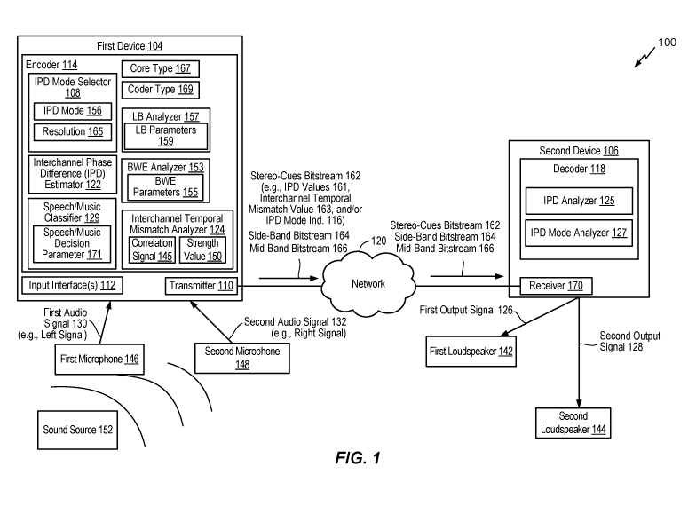
[0075] The first device 104 may include an encoder 114, a transmitter 110, one
or more
input interfaces 112, or a combination thereof A first input interface of the
input
interfaces112 may be coupled to a first microphone 146. A second input
interface of the
input interface(s) 112 may be coupled to a second microphone 148. The encoder
114
may include an interchannel temporal mismatch (ITM) analyzer 124, an IPD mode
selector 108, an IPD estimator 122, a speech/music classifier 129, a LB
analyzer 157, a
bandwidth extension (BWE) analyzer 153, or a combination thereof The encoder
114
may be configured to downmix and encode multiple audio signals, as described
herein.
[0076] The second device 106 may include a decoder 118 and a receiver 170. The
decoder 118 may include an IPD mode analyzer 127, an IPD analyzer 125, or
both. The
decoder 118 may be configured to upmix and render multiple channels. The
second
device 106 may be coupled to a first loudspeaker 142, a second loudspeaker
144, or
both. Although FIG. 1 illustrates an example in which one device includes an
encoder
and another device includes a decoder, it is to be understood that in
alternative aspects,
devices may include both encoders and decoders.
[0077] During operation, the first device 104 may receive a first audio signal
130 via
the first input interface from the first microphone 146 and may receive a
second audio
signal 132 via the second input interface from the second microphone 148. The
first
audio signal 130 may correspond to one of a right channel signal or a left
channel
signal. The second audio signal 132 may correspond to the other of the right
channel
signal or the left channel signal. A sound source 152 (e.g., a user, a
speaker, ambient
noise, a musical instrument, etc.) may be closer to the first microphone 146
than to the
second microphone 148, as shown in FIG. 1. Accordingly, an audio signal from
the
sound source 152 may be received at the input interface(s) 112 via the first
microphone
146 at an earlier time than via the second microphone 148. This natural delay
in the
multi-channel signal acquisition through the multiple microphones may
introduce an
interchannel temporal mismatch between the first audio signal 130 and the
second audio
signal 132.
[0078] The interchannel temporal mismatch analyzer 124 may determine an
interchannel temporal mismatch value 163 (e.g., a non-causal shift value)
indicative of
CA 03024146 2018-11-13
WO 2017/222871
PCT/US2017/037198
- 21 -
the shift (e.g., a non-causal shift) of the first audio signal 130 relative to
the second
audio signal 132. In this example, the first audio signal 130 may be referred
to as a
"target" signal and the second audio signal 132 may be referred to as a
"reference"
signal. A first value (e.g., a positive value) of the interchannel temporal
mismatch value
163 may indicate that the second audio signal 132 is delayed relative to the
first audio
signal 130. A second value (e.g., a negative value) of the interchannel
temporal
mismatch value 163 may indicate that the first audio signal 130 is delayed
relative to the
second audio signal 132. A third value (e.g., 0) of the interchannel temporal
mismatch
value 163 may indicate that there is no temporal misalignment (e.g., no
temporal delay)
between the first audio signal 130 and the second audio signal 132.
[0079] The interchannel temporal mismatch analyzer 124 may determine the
interchannel temporal mismatch value 163, a strength value 150, or both, based
on a
comparison of a first frame of the first audio signal 130 and a plurality of
frames of the
second audio signal 132 (or vice versa), as further described with reference
to FIG. 4.
The interchannel temporal mismatch analyzer 124 may generate an adjusted first
audio
signal 130 (or an adjusted second audio signal 132, or both) by adjusting the
first audio
signal 130 (or the second audio signal 132, or both) based on the interchannel
temporal
mismatch value 163, as further described with reference to FIG. 4. The
speech/music
classifier 129 may determine a speech/music decision parameter 171 based on
the first
audio signal 130, the second audio signal 132, or both, as further described
with
reference to FIG. 4. The speech/music decision parameter 171 may indicate
whether
first frame of the first audio signal 130 more closely corresponds to (and is
therefore
more likely to include) speech or music.
[0080] The encoder 114 may be configured to determine a core type 167, a coder
type
169, or both. For example, prior to encoding of the first frame of the first
audio signal
130, a second frame of the first audio signal 130 may have been encoded based
on a
previous core type, a previous coder type, or both. Alternatively, the core
type 167 may
correspond to the previous core type, the coder type 169 may correspond to the
previous
coder type, or both. In an alternative aspect, the core type 167 corresponds
to a
predicted core type, the coder type 169 corresponds to a predicted coder type,
or both.
The encoder 114 may determine the predicted core type, the predicted coder
type, or
CA 03024146 2018-11-13
WO 2017/222871
PCT/US2017/037198
- 22 -
both, based on the first audio signal 130 and the second audio signal 132, as
further
described with reference to FIG. 2. Thus, the values of the core type 167 and
the coder
type 169 may be set to the respective values that were used to encode a
previous frame,
or such values may be predicted independent of the values that were used to
encode the
previous frame.
[0081] The LB analyzer 157 is configured to determine one or more LB
parameters 159
based on the first audio signal 130, the second audio signal 132, or both, as
further
described with reference to FIG. 2. The LB parameters 159 include a core
sample rate
(e.g., 12.8 kHz or 16 kHz), a pitch value, a voicing factor, a voicing
activity parameter,
another LB characteristic, or a combination thereof The BWE analyzer 153 is
configured to determine one or more BWE parameters 155 based on the first
audio
signal 130, the second audio signal 132, or both, as further described with
reference to
FIG. 2. The BWE parameters 155 include one or more interchannel BWE
parameters,
such as a gain mapping parameter, a spectral mapping parameter, an
interchannel BWE
reference channel indicator, or a combination thereof
[0082] The IPD mode selector 108 may select an IPD mode 156 based on the
interchannel temporal mismatch value 163, the strength value 150, the core
type 167,
the coder type 169, the LB parameters 159, the BWE parameters 155, the
speech/music
decision parameter 171, or a combination thereof, as further described with
reference to
FIG. 4. The IPD mode 156 may correspond to a resolution 165, that is, a number
of bits
to be used to represent an IPD value. The IPD estimator 122 may generate IPD
values
161 having the resolution 165, as further described with reference to FIG. 4.
In a
particular implementation, the resolution 165 corresponds to a count of the
IPD values
161. For example, a first IPD value may correspond to a first frequency band,
a second
IPD value may correspond to a second frequency band, and so on. In this
implementation, the resolution 165 indicates a number of frequency bands for
which an
IPD value is to be included in the IPD values 161. In a particular aspect, the
resolution
165 corresponds to a range of phase values. For example, the resolution 165
corresponds to a number of bits to represent a value included in the range of
phase
values.
CA 03024146 2018-11-13
WO 2017/222871
PCT/US2017/037198
- 23 -
[0083] In a particular aspect, the resolution 165 indicates a number of bits
(e.g., a
quantization resolution) to be used to represent absolute IPD values. For
example, the
resolution 165 may indicate that a first number of bits are (e.g., a first
quantization
resolution is) to be used to represent a first absolute value of a first IPD
value
corresponding to a first frequency band, that a second number of bits are
(e.g., a second
quantization resolution is) to be used to represent a second absolute value of
a second
IPD value corresponding to a second frequency band, that additional bits to be
used to
represent additional absolute IPD values corresponding to additional frequency
bands,
or a combination thereof The IPD values 161 may include the first absolute
value, the
second absolute value, the additional absolute IPD values, or a combination
thereof In
a particular aspect, the resolution 165 indicates a number of bits to be used
to represent
an amount of temporal variance of IPD values across frames. For example, first
IPD
values may be associated with a first frame and second IPD values may be
associated
with a second frame. The IPD estimator 122 may determine an amount of temporal
variance based on a comparison of the first IPD values and the second IPD
values. The
IPD values 161 may indicate the amount of temporal variance. In this aspect,
the
resolution 165 indicates a number of bits used to represent the amount of
temporal
variance. The encoder 114 may generate an IPD mode indicator 116 indicating
the IPD
mode 156, the resolution 165, or both.
[0084] The encoder 114 may generate a side-band bitstream 164, a mid-band
bitstream
166, or both, based on the first audio signal 130, the second audio signal
132, the IPD
values 161, the interchannel temporal mismatch value 163, or a combination
thereof, as
further described with reference to FIGS. 2-3. For example, the encoder 114
may
generate the side-band bitstream 164, the mid-band bitstream 166, or both,
based on the
adjusted first audio signal 130 (e.g., a first aligned audio signal), the
second audio signal
132 (e.g., a second aligned audio signal), the IPD values 161, the
interchannel temporal
mismatch value 163, or a combination thereof As another example, the encoder
114
may generate the side-band bitstream 164, the mid-band bitstream 166, or both,
based
on the first audio signal 130, the adjusted second audio signal 132, the IPD
values 161,
the interchannel temporal mismatch value 163, or a combination thereof The
encoder
114 may also generate a stereo-cues bitstream 162 indicating the IPD values
161, the
CA 03024146 2018-11-13
WO 2017/222871
PCT/US2017/037198
- 24 -
interchannel temporal mismatch value 163, the IPD mode indicator 116, the core
type
167, the coder type 169, the strength value 150, the speech/music decision
parameter
171, or a combination thereof
[0085] The transmitter 110 may transmit the stereo-cues bitstream 162, the
side-band
bitstream 164, the mid-band bitstream 166, or a combination thereof, via the
network
120, to the second device 106. Alternatively, or in addition, the transmitter
110 may
store the stereo-cues bitstream 162, the side-band bitstream 164, the mid-band
bitstream
166, or a combination thereof, at a device of the network 120 or a local
device for
further processing or decoding at a later point in time. When the resolution
165
corresponds to more than zero bits, the IPD values 161 in addition to the
interchannel
temporal mismatch value 163 may enable finer subband adjustments at a decoder
(e.g.,
the decoder 118 or a local decoder). When the resolution 165 corresponds to
zero bits,
the stereo-cues bitstream 162 may have fewer bits or may have bits available
to include
stereo-cues parameter(s) other than IPD.
[0086] The receiver 170 may receive, via the network 120, the stereo-cues
bitstream
162, the side-band bitstream 164, the mid-band bitstream 166, or a combination
thereof
The decoder 118 may perform decoding operations based on the stereo-cues
bitstream
162, the side-band bitstream 164, the mid-band bitstream 166, or a combination
thereof,
to generate output signals 126, 128 corresponding to decoded versions of the
input
signals 130, 132. For example, the IPD mode analyzer 127 may determine that
the
stereo-cues bitstream 162 includes the IPD mode indicator 116 and that the IPD
mode
indicator 116 indicates the IPD mode 156. The IPD analyzer 125 may extract the
IPD
values 161 from the stereo-cues bitstream 162 based on the resolution 165
corresponding to the IPD mode 156. The decoder 118 may generate the first
output
signal 126 and the second output signal 128 based on the IPD values 161, the
side-band
bitstream 164, the mid-band bitstream 166, or a combination thereof, as
further
described with reference to FIG. 7. The second device 106 may output the first
output
signal 126 via the first loudspeaker 142. The second device 106 may output the
second
output signal 128 via the second loudspeaker 144. In alternative examples, the
first
output signal 126 and second output signal 128 may be transmitted as a stereo
signal
pair to a single output loudspeaker.
CA 03024146 2018-11-13
WO 2017/222871
PCT/US2017/037198
- 25 -
[0087] The system 100 may thus enable the encoder 114 to dynamically adjust a
resolution of the IPD values 161 based on various characteristics. For
example, the
encoder 114 may determine a resolution of the IPD values based on the
interchannel
temporal mismatch value 163, the strength value 150, the core type 167, the
coder type
169, the speech/music decision parameter 171, or a combination thereof The
encoder
114 may thus use have more bits available to encode other information when the
IPD
values 161 have a low resolution (e.g., zero resolution) and may enable
performance of
finer subband adjustments at a decoder when the IPD values 161 have a higher
resolution.
[0088] Referring to FIG. 2, an illustrative example of the encoder 114 is
shown. The
encoder 114 includes the interchannel temporal mismatch analyzer 124 coupled
to a
stereo-cues estimator 206. The stereo-cues estimator 206 may include the
speech/music
classifier 129, the LB analyzer 157, the BWE analyzer 153, the IPD mode
selector 108,
the IPD estimator 122, or a combination thereof
[0089] A transformer 202 may be coupled, via the interchannel temporal
mismatch
analyzer 124, to the stereo-cues estimator 206, a side-band signal generator
208, a mid-
band signal generator 212, or a combination thereof A transformer 204 may be
coupled, via the interchannel temporal mismatch analyzer 124, to the stereo-
cues
estimator 206, the side-band signal generator 208, the mid-band signal
generator 212, or
a combination thereof The side-band signal generator 208 may be coupled to a
side-
band encoder 210. The mid-band signal generator 212 may be coupled to a mid-
band
encoder 214. The stereo-cues estimator 206 may be coupled to the side-band
signal
generator 208, the side-band encoder 210, the mid-band signal generator 212,
or a
combination thereof
[0090] In some examples, the first audio signal 130 of FIG. 1 may include a
left-
channel signal and the second audio signal 132 of FIG. 1 may include a right-
channel
signal. A time-domain left signal (Lt) 290 may correspond to the first audio
signal 130
and a time-domain right signal (Rt) 292 may correspond to the second audio
signal 132.
However, it should be understood that in other examples, the first audio
signal 130 may
include a right-channel signal and the second audio signal 132 may include a
left-
CA 03024146 2018-11-13
WO 2017/222871
PCT/US2017/037198
- 26 -
channel signal. In such examples, the time-domain right signal (Rt) 292 may
correspond to the first audio signal 130 and a time-domain left signal (Lt)
290 may
correspond to the second audio signal 132. It is also to be understood that
the various
components illustrated in FIGS. 1-4, 7-8, and 10 (e.g., transforms, signal
generators,
encoders, estimators, etc.) may be implemented using hardware (e.g., dedicated
circuitry), software (e.g., instructions executed by a processor), or a
combination
thereof
[0091] During operation, the transformer 202 may perform a transform on the
time-
domain left signal (Lt) 290 and the transformer 204 may perform a transform on
the
time-domain right signal (Rt) 292. The transformers 202, 204 may perform
transform
operations that generate frequency-domain (or sub-band domain) signals. As non-
limiting examples, the transformers 202, 204 may perform Discrete Fourier
Transform
(DFT) operations, Fast Fourier Transform (FFT) operations, etc. In a
particular
implementation, Quadrature Mirror Filterbank (QMF) operations (using
filterbanks,
such as a Complex Low Delay Filter Bank) are used to split the input signals
290, 292
into multiple sub-bands, and the sub-bands may be converted into the frequency-
domain
using another frequency-domain transform operation. The transformer 202 may
generate a frequency-domain left signal (Lfr(b)) 229 by transforming the time-
domain
left signal (Lt) 290, and the transformer 304 may generate a frequency-domain
right
signal (Rfr(b)) 231 by transforming the time-domain right signal (Rt) 292.
[0092] The interchannel temporal mismatch analyzer 124 may generate the
interchannel
temporal mismatch value 163, the strength value 150, or both, based on the
frequency-
domain left signal (Lfr(b)) 229 and the frequency-domain right signal (Rfr(b))
231, as
described with reference to FIG. 4. The interchannel temporal mismatch value
163 may
provide an estimate of a temporal mismatch between the frequency-domain left
signal
(Lfr(b)) 229 and the frequency-domain right signal (Rfr(b)) 231. The
interchannel
temporal mismatch value 163 may include an ICA value 262. The interchannel
temporal mismatch analyzer 124 may generate a frequency-domain left signal
(Lfr(b))
230 and a frequency-domain right signal (Rfr(b)) 232 based on the frequency-
domain
left signal (Lfr(b)) 229, the frequency-domain right signal (Rfr(b)) 231, and
the
interchannel temporal mismatch value 163. For example, the interchannel
temporal
CA 03024146 2018-11-13
WO 2017/222871
PCT/US2017/037198
- 27 -
mismatch analyzer 124 may generate the frequency-domain left signal (Lfr(b))
230 by
shifting the frequency-domain left signal (Lfr(b)) 229 based on an ITM value
264. The
frequency-domain right signal (Rfr(b)) 232 may correspond to the frequency-
domain
right signal (Rfr(b)) 231. Alternatively, the interchannel temporal mismatch
analyzer
124 may generate the frequency-domain right signal (Rfr(b)) 232 by shifting
the
frequency-domain right signal (Rfr(b)) 231 based on the ITM value 264. The
frequency-
domain left signal (Lfr(b)) 230 may correspond to the frequency-domain left
signal
(Lfr(b)) 229.
[0093] In a particular aspect, the interchannel temporal mismatch analyzer 124
generates the interchannel temporal mismatch value 163, the strength value
150, or
both, based on the time-domain left signal (Lt) 290 and the time-domain right
signal (Rt)
292, as described with reference to FIG. 4. In this aspect, the interchannel
temporal
mismatch value 163 includes the ITM value 264 rather than the ICA value 262,
as
described with reference to FIG. 4. The interchannel temporal mismatch
analyzer 124
may generate the frequency-domain left signal (Lfr(b)) 230 and the frequency-
domain
right signal (Rfr(b)) 232 based on the time-domain left signal (Lt) 290, the
time-domain
right signal (Rt) 292, and the interchannel temporal mismatch value 163. For
example,
the interchannel temporal mismatch analyzer 124 may generate an adjusted time-
domain left signal (Lt) 290 by shifting the time-domain left signal (Lt) 290
based on the
ICA value 262. The interchannel temporal mismatch analyzer 124 may generate
the
frequency-domain left signal (Lfr(b)) 230 and the frequency-domain right
signal (Rfr(b))
232 by performing a transform on the adjusted time-domain left signal (Lt) 290
and the
time-domain right signal (Rt) 292, respectively. Alternatively, the
interchannel
temporal mismatch analyzer 124 may generate an adjusted time-domain right
signal (Rt)
292 by shifting the time-domain right signal (Rt) 292 based on the ICA value
262. The
interchannel temporal mismatch analyzer 124 may generate the frequency-domain
left
signal (Lfr(b)) 230 and the frequency-domain right signal (Rfr(b)) 232 by
performing a
transform on the time-domain left signal (Lt) 290 and the adjusted time-domain
right
signal (Rt) 292, respectively. Alternatively, the interchannel temporal
mismatch
analyzer 124 may generate an adjusted time-domain left signal (Lt) 290 by
shifting the
time-domain left signal (Lt) 290 based on the ICA value 262 and generate an
adjusted
CA 03024146 2018-11-13
WO 2017/222871
PCT/US2017/037198
- 28 -
time-domain right signal (Rt) 292 by shifting the time-domain right signal
(Rt) 292
based on the ICA value 262. The interchannel temporal mismatch analyzer 124
may
generate the frequency-domain left signal (Lfr(b)) 230 and the frequency-
domain right
signal (Rfr(b)) 232 by performing a transform on the adjusted time-domain left
signal
(Lt) 290 and the adjusted time-domain right signal (Rt) 292, respectively.
[0094] The stereo-cues estimator 206 and the side-band signal generator 208
may each
receive the interchannel temporal mismatch value 163, the strength value 150,
or both,
from the interchannel temporal mismatch analyzer 124. The stereo-cues
estimator 206
and the side-band signal generator 208 may also receive the frequency-domain
left
signal (Lfr(b)) 230 from the transformer 202, the frequency-domain right
signal (Rfr(b))
232 from the transformer 204, or a combination thereof The stereo-cues
estimator 206
may generate the stereo-cues bitstream 162 based on the frequency-domain left
signal
(Lfr(b)) 230, the frequency-domain right signal (Rfr(b)) 232, the interchannel
temporal
mismatch value 163, the strength value 150, or a combination thereof For
example, the
stereo-cues estimator 206 may generate the IPD mode indicator 116, the IPD
values
161, or both, as described with reference to FIG. 4. The stereo-cues estimator
206 may
alternatively be referred to as a "stereo-cues bitstream generator." The IPD
values 161
may provide an estimate of the phase difference, in the frequency-domain,
between the
frequency-domain left signal (Lfr(b)) 230 and the frequency-domain right
signal (Rfr(b))
232. In a particular aspect, the stereo-cues bitstream 162 includes additional
(or
alternative) parameters, such as IID, etc. The stereo-cues bitstream 162 may
be
provided to the side-band signal generator 208 and to the side-band encoder
210.
[0095] The side-band signal generator 208 may generate a frequency-domain side-
band
signal (Sfr(b)) 234 based on the frequency-domain left signal (Lfr(b)) 230,
the frequency-
domain right signal (Rfr(b)) 232, the interchannel temporal mismatch value
163, the IPD
values 161, or a combination thereof In a particular aspect, the frequency-
domain side-
band signal 234 is estimated in frequency-domain bins/bands and the IPD values
161
correspond to a plurality of bands. For example, a first IPD value of the IPD
values 161
may correspond to a first frequency band. The side-band signal generator 208
may
generate a phase-adjusted frequency-domain left signal (Lfr(b)) 230 by
performing a
phase shift on the frequency-domain left signal (Lfr(b)) 230 in the first
frequency band
CA 03024146 2018-11-13
WO 2017/222871
PCT/US2017/037198
- 29 -
based on the first IPD value. The side-band signal generator 208 may generate
a phase-
adjusted frequency-domain right signal (Rfr(b)) 232 by performing a phase
shift on the
frequency-domain right signal (Rfr(b)) 232 in the first frequency band based
on the first
IPD value. This process may be repeated for other frequency bands/bins.
[0096] The phase-adjusted frequency-domain left signal (Lfr(b)) 230 may
correspond to
ci(b)*Lfr(b) and the phase-adjusted frequency-domain right signal (Rfr(b)) 232
may
correspond to c2(b)*Rfr(b), where Lfr(b) corresponds to the frequency-domain
left signal
(Lfr(b)) 230, Rfr(b) corresponds to the frequency-domain right signal (Rfr(b))
232, and
ci(b) and c2(b) are complex values that are based on the IPD values 161. In a
particular
implementation, ci(b) = (cos(-y) - i*sin(y))/2" and c2(b) = (cos(IPD(b)-y) +
i*sin(IPD(b)-y))/2" , where i is the imaginary number signifying the square
root of -1
and IPD(b) is one of the IPD values 161 associated with a particular subband
(b). In a
particular aspect, the IPD mode indicator 116 indicates that the IPD values
161 have a
particular resolution (e.g., 0). In this aspect, the phase-adjusted frequency-
domain left
signal (Lfr(b)) 230 corresponds to the frequency-domain left signal (Lfr(b))
230, whereas
the phase-adjusted frequency-domain right signal (Rfr(b)) 232 corresponds to
the
frequency-domain right signal (Rfr(b)) 232.
[0097] The side-band signal generator 208 may generate the frequency-domain
side-
band signal (Sfr(b)) 234 based on the phase-adjusted frequency-domain left
signal
(Lfr(b)) 230 and the phase-adjusted frequency-domain right signal (Rfr(b))
232. The
frequency-domain side-band signal (Sfr(b)) 234 may be expressed as (1(fr)-
r(fr))/2,
where l(fr) includes the phase-adjusted frequency-domain left signal (Lfr(b))
230 and
r(fr) includes the phase-adjusted frequency-domain right signal (Rfr(b)) 232.
The
frequency-domain side-band signal (Sfr(b)) 234 may be provided to the side-
band
encoder 210.
[0098] The mid-band signal generator 212 may receive the interchannel temporal
mismatch value 163 from the interchannel temporal mismatch analyzer 124, the
frequency-domain left signal (Lfr(b)) 230 from the transformer 202, the
frequency-
domain right signal (Rfr(b)) 232 from the transformer 204, the stereo-cues
bitstream 162
from the stereo-cues estimator 206, or a combination thereof The mid-band
signal
CA 03024146 2018-11-13
WO 2017/222871
PCT/US2017/037198
- 30 -
generator 212 may generate the phase-adjusted frequency-domain left signal
(Lfr(b))
230 and the phase-adjusted frequency-domain right signal (Rfr(b)) 232, as
described
with reference to the side-band signal generator 208. The mid-band signal
generator
212 may generate a frequency-domain mid-band signal (Mfr(b)) 236 based on the
phase-
adjusted frequency-domain left signal (Lfr(b)) 230 and the phase-adjusted
frequency-
domain right signal (Rfr(b)) 232. The frequency-domain mid-band signal
(Mfr(b)) 236
may be expressed as (1(0+40)/2, where 1(t) includes the phase-adjusted
frequency-
domain left signal (Lfr(b)) 230 and r(t) includes the phase-adjusted frequency-
domain
right signal (Rfr(b)) 232. The frequency-domain mid-band signal (Mfr(b)) 236
may be
provided to the side-band encoder 210. The frequency-domain mid-band signal
(Mfr(b))
236 may be also provided to the mid-band encoder 214.
[0099] In a particular aspect, the mid-band signal generator 212 selects a
frame core
type 267, a frame coder type 269, or both, to be used to encode the frequency-
domain
mid-band signal (Mfr(b)) 236. For example, the mid-band signal generator 212
may
select an algebraic code-excited linear prediction (ACELP) core type, a
transform coded
excitation (TCX) core type, or another core type as the frame core type 267.
To
illustrate, the mid-band signal generator 212 may, in response to determining
that the
speech/music classifier 129 indicates that the frequency-domain mid-band
signal
(Mfr(b)) 236 corresponds to speech, select the ACELP core type as the frame
core type
267. Alternatively, the mid-band signal generator 212 may, in response to
determining
that the speech/music classifier 129 indicates that the frequency-domain mid-
band
signal (Mfr(b)) 236 corresponds to non-speech (e.g., music), select the TCX
core type as
the frame core type 267.
[0100] The LB analyzer 157 is configured to determine the LB parameters 159 of
FIG.
1. The LB parameters 159 correspond to the time-domain left signal (Lt) 290,
the time-
domain right signal (Rt) 292, or both. In a particular example, the LB
parameters 159
include a core sample rate. In a particular aspect, the LB analyzer 157 is
configured to
determine the core sample rate based on the frame core type 267. For example,
the LB
analyzer 157 is configured to select a first sample rate (e.g., 12.8 kHz) as
the core
sample rate in response to determining that the frame core type 267
corresponds to the
ACELP core type. Alternatively, the LB analyzer 157 is configured to select a
second
CA 03024146 2018-11-13
WO 2017/222871
PCT/US2017/037198
- 31 -
sample rate (e.g., 16 kHz) as the core sample rate in response to determining
that the
frame core type 267 corresponds to a non-ACELP core type (e.g., the TCX core
type).
In an alternate aspect, the LB analyzer 157 is configured to determine the
core sample
rate based on a default value, a user input, a configuration setting, or a
combination
thereof
[0101] In a particular aspect, the LB parameters 159 include a pitch value, a
voice
activity parameter, a voicing factor, or a combination thereof The pitch value
may be
indicative of a differential pitch period or an absolute pitch period
corresponding to the
time-domain left signal (Lt) 290, the time-domain right signal (Rt) 292, or
both. The
voice activity parameter may be indicative of whether speech is detected in
the time-
domain left signal (Lt) 290, the time-domain right signal (Rt) 292, or both.
The voicing
factor (e.g., a value from 0.0 to 1.0) indicates a voiced/unvoiced nature
(e.g., strongly
voiced, weakly voiced, weakly unvoiced, or strongly unvoiced) of the time-
domain left
signal (Lt) 290, the time-domain right signal (Rt) 292, or both.
[0102] The BWE analyzer 153 is configured to determine the BWE parameters 155
based on the time-domain left signal (Lt) 290, the time-domain right signal
(Rt) 292, or
both. The BWE parameters 155 include a gain mapping parameter, a spectral
mapping
parameter, an interchannel BWE reference channel indicator, or a combination
thereof
For example, the BWE analyzer 153 is configured to determine the gain mapping
parameter based on a comparison of a high-band signal and a synthesized high-
band
signal. In a particular aspect, the high-band signal and the synthesized high-
band signal
correspond to the time-domain left signal (Lt) 290. In a particular aspectõ
the high-
band signal and the synthesized high-band signal correspond to the time-domain
right
signal (Rt) 292. In a particular example, the BWE analyzer 153 is configured
to
determine the spectral mapping parameter based on a comparison of the high-
band
signal and the synthesized high-band signal. To illustrate, the BWE analyzer
153 is
configured to generate a gain-adjusted synthesized signal by applying the gain
parameter to the synthesized high-band signal, and to generate the spectral
mapping
parameter based on a comparison of the gain-adjusted synthesized signal and
the high-
band signal. The spectral mapping parameter is indicative of a spectral tilt.
CA 03024146 2018-11-13
WO 2017/222871
PCT/US2017/037198
- 32 -
[0103] The mid-band signal generator 212 may, in response to determining that
the
speech/music classifier 129 indicates that the frequency-domain mid-band
signal
(Mrr(b)) 236 corresponds to speech, select a general signal coding (GSC) coder
type or a
non-GSC coder type as the frame coder type 269. For example, the mid-band
signal
generator 212 may select the non-GSC coder type (e.g., modified discrete
cosine
transform (MDCT)) in response to determining that the frequency-domain mid-
band
signal (Mrr(b)) 236 corresponds to high spectral sparseness (e.g., higher than
a
sparseness threshold). Alternatively, the mid-band signal generator 212 may
select the
GSC coder type in response to determining that the frequency-domain mid-band
signal
(Mrr(b)) 236 corresponds to a non-sparse spectrum (e.g., lower than the
sparseness
threshold).
[0104] The mid-band signal generator 212 may provide the frequency-domain mid-
band
signal (Mrr(b)) 236 to the mid-band encoder 214 for encoding based on the
frame core
type 267, the frame coder type 269, or both. The frame core type 267, the
frame coder
type 269, or both, may be associated with a first frame of the frequency-
domain mid-
band signal (Mrr(b)) 236 that is to be encoded by the mid-band encoder 214.
The frame
core type 267 may be stored in a memory as a previous frame core type 268. The
frame
coder type 269 may be stored in the memory as a previous frame coder type 270.
The
stereo-cues estimator 206 may use the previous frame core type 268, the
previous frame
coder type 270, or both to determine the stereo-cues bitstream 162 with
respect to a
second frame of the frequency-domain mid-band signal (Mrr(b)) 236, as
described with
reference to FIG. 4. It should be understood that grouping of various
components in the
drawings is for ease of illustration and is non-limiting. For example, the
speech/music
classifier 129 may be included in any component along the mid-signal
generation path.
To illustrate, the speech/music classifier 129 may be included in the mid-band
signal
generator 212. The mid-band signal generator 212 may generate a speech/music
decision parameter. The speech/music decision parameter may be stored in the
memory
as the speech/music decision parameter 171 of FIG. 1. The stereo-cues
estimator 206 is
configured to use the speech/music decision parameter 171, the LB parameters
159, the
BWE parameters 155, or a combination thereof, to determine the stereo-cues
bitstream
CA 03024146 2018-11-13
WO 2017/222871
PCT/US2017/037198
- 33 -
162 with respect to the second frame of the frequency-domain mid-band signal
(Mfr(b))
236, as described with reference to FIG. 4.
[0105] The side-band encoder 210 may generate the side-band bitstream 164
based on
the stereo-cues bitstream 162, the frequency-domain side-band signal (Sfr(b))
234, and
the frequency-domain mid-band signal (Mfr(b)) 236. The mid-band encoder 214
may
generate the mid-band bitstream 166 by encoding the frequency-domain mid-band
signal (Mfr(b)) 236. In particular examples, the side-band encoder 210 and the
mid-
band encoder 214 may include ACELP encoders, TCX encoders, or both, to
generate
the side-band bitstream 164 and the mid-band bitstream 166, respectively. For
lower
bands, the frequency-domain side-band signal (Sfr(b)) 334 may be encoded using
a
transform-domain coding technique. For higher bands, the frequency-domain side-
band
signal (Sfr(b)) 234 may be expressed as a prediction from the previous frame's
mid-band
signal (either quantized or unquantized).
[0106] The mid-band encoder 214 may transform the frequency-domain mid-band
signal (Mfr(b)) 236 to any other transform/time-domain before encoding. For
example,
the frequency-domain mid-band signal (Mfr(b)) 236 may be inverse-transformed
back to
the time-domain, or transformed to MDCT domain for coding.
[0107] FIG. 2 thus illustrates an example of the encoder 114 in which the core
type
and/or coder type of a previously encoded frame are used to determine an IPD
mode,
and thus determine a resolution of the IPD values in the stereo-cues bitstream
162. In
an alternative aspect, the encoder 114 uses predicted core and/or coder types
rather than
values from previous frame. For example, FIG. 3 depicts an illustrative
example of the
encoder 114 in which the stereo-cues estimator 206 can determine the stereo-
cues
bitstream 162 based on a predicted core type 368, a predicted coder type 370,
or both.
[0108] The encoder 114 includes a downmixer 320 couple to a pre-processor 318.
The
pre-processor 318 is coupled, via a multiplexer (MUX) 316, to the stereo-cues
estimator
206. The downmixer 320 may generate an estimated time-domain mid-band signal
(Mt)
396 by downmixing the time-domain left signal (Lt) 290 and the time-domain
right
signal (Rt) 292 based on the interchannel temporal mismatch value 163. For
example,
the downmixer 320 may generate the adjusted time-domain left signal (Lt) 290
by
CA 03024146 2018-11-13
WO 2017/222871
PCT/US2017/037198
- 34 -
adjusting the time-domain left signal (Lt) 290 based on the interchannel
temporal
mismatch value 163, as described with reference to FIG. 2. The downmixer 320
may
generate the estimated time-domain mid-band signal (Mt) 396 based on the
adjusted
time-domain left signal (Lt) 290 and the time-domain right signal (Rt) 292.
The
estimated time-domain mid-band signal (Mt) 396 may be expressed as (1(0+40)/2,
where 1(t) includes the adjusted time-domain left signal (Lt) 290 and r(t)
includes the
time-domain right signal (Rt) 292. As another example, the downmixer 320 may
generate the adjusted time-domain right signal (Rt) 292 by adjusting the time-
domain
right signal (Rt) 292 based on the interchannel temporal mismatch value 163,
as
described with reference to FIG. 2. The downmixer 320 may generate the
estimated
time-domain mid-band signal (Mt) 396 based on the time-domain left signal (Lt)
290
and the adjusted time-domain right signal (Rt) 292. The estimated time-domain
mid-
band signal (Mt) 396 may be expressed as (1(0+40)/2, where 1(t) includes the
time-
domain left signal (Lt) 290 and r(t) includes the adjusted time-domain right
signal (Rt)
292.
[0109] Alternatively, the downmixer 320 may operate in the frequency domain
rather
than in the time domain. To illustrate, the downmixer 320 may generate an
estimated
frequency-domain mid-band signal Mfr(b) 336 by downmixing the frequency-domain
left signal (Lfr(b)) 229 and the frequency-domain right signal (Rfr(b)) 231
based on the
interchannel temporal mismatch value 163. For example, the downmixer 320 may
generate the frequency-domain left signal (Lfr(b)) 230 and the frequency-
domain right
signal (Rfr(b)) 232 based on the interchannel temporal mismatch value 163, as
described
with reference to FIG. 2. The downmixer 320 may generate the estimated
frequency-
domain mid-band signal Mfr(b) 336 based on the frequency-domain left signal
(Lfr(b))
230 and the frequency-domain right signal (Rfr(b)) 232. The estimated
frequency-
domain mid-band signal Mfr(b) 336 may be expressed as (1(0+40)/2, where 1(t)
includes
the frequency-domain left signal (Lfr(b)) 230 and r(t) includes the frequency-
domain
right signal (Rfr(b)) 232.
[0110] The downmixer 320 may provide the estimated time-domain mid-band signal
(Mt) 396 (or the estimated frequency-domain mid-band signal Mfr(b) 336) to the
pre-
processor 318. The pre-processor 318 may determine a predicted core type 368,
a
CA 03024146 2018-11-13
WO 2017/222871
PCT/US2017/037198
- 35 -
predicted coder type 370, or both, based on a mid-band signal, as described
with
reference to the mid-band signal generator 212. For example, the pre-processor
318
may determine the predicted core type 368, the predicted coder type 370, or
both, based
on a speech/music classification of the mid-band signal, a spectral sparseness
of the
mid-band signal, or both. In a particular aspect, the pre-processor 318
determines a
predicted speech/music decision parameter based on a speech/music
classification of the
mid-band signal and determines the predicted core type 368, the predicted
coder type
370, or both, based on the predicted speech/music decision parameter, a
spectral
sparseness of the mid-band signal, or both. The mid-band signal may include
the
estimated time-domain mid-band signal (Mt) 396 (or the estimated frequency-
domain
mid-band signal Mfr(b) 336).
[0111] The pre-processor 318 may provide the predicted core type 368, the
predicted
coder type 370, the predicted speech/music decision parameter, or a
combination
thereof, to the MUX 316. The MUX 316 may select between outputting, to the
stereo-
cues estimator 206, predicted coding information (e.g., the predicted core
type 368, the
predicted coder type 370, the predicted speech/music decision parameter, or a
combination thereof) or previous coding information (e.g., the previous frame
core type
268, the previous frame coder type 270, a previous frame speech/music decision
parameter, or a combination thereof) associated with a previously encoded
frame of the
frequency-domain mid-band signal Mfr(b) 236. For example, the MUX 316 may
select
between the predicted coding information or the previous coding information
based on a
default value, a value corresponding to a user input, or both.
[0112] Providing the previous coding information (e.g., the previous frame
core type
268, the previous frame coder type 270, the previous frame speech/music
decision
parameter, or a combination thereof) to the stereo-cues estimator 206, as
described with
reference to FIG. 2, may conserve resources (e.g., time, processing cycles, or
both) that
would be used to determine the predicted coding information (e.g., the
predicted core
type 368, the predicted coder type 370, the predicted speech/music decision
parameter,
or a combination thereof). Conversely, when there is high frame-to-frame
variation in
characteristics of the first audio signal 130 and/or the second audio signal
132, the
predicted coding information (e.g., the predicted core type 368, the predicted
coder type
CA 03024146 2018-11-13
WO 2017/222871
PCT/US2017/037198
- 36 -
370, the predicted speech/music decision parameter, or a combination thereof)
may
correspond more accurately with the core type, the coder type, the
speech/music
decision parameter, or a combination thereof, selected by the mid-band signal
generator
212. Thus, dynamically switching between outputting the previous coding
information
or the predicted coding information to the stereo-cues estimator 206 (e.g.,
based on an
input to the MUX 316) may enable balancing resource usage and accuracy.
[0113] Referring to FIG. 4, an illustrative example of the stereo-cues
estimator 206 is
shown. The stereo-cues estimator 206 may be coupled to the interchannel
temporal
mismatch analyzer 124, which may determine a correlation signal 145 based on a
comparison of a first frame of a left signal (L) 490 and a plurality of frames
of a right
signal (R) 492. In a particular aspect, the left signal (L) 490 corresponds to
the time-
domain left signal (Lt) 290, whereas the right signal (R) 492 corresponds to
the time-
domain right signal (Rt) 292. In an alternative aspect, the left signal (L)
490
corresponds to the frequency-domain left signal (Lfr(b)) 229, whereas the
right signal
(R) 492 corresponds to the frequency-domain right signal (Rfr(b)) 231.
[0114] Each of the plurality of frames of the right signal (R) 492 may
correspond to a
particular interchannel temporal mismatch value. For example, a first frame of
the right
signal (R) 492 may correspond to the interchannel temporal mismatch value 163.
The
correlation signal 145 may indicate a correlation between the first frame of
the left
signal (L) 490 and each of the plurality of frames of the right signal (R)
492.
[0115] Alternatively, the interchannel temporal mismatch analyzer 124 may
determine
the correlation signal 145 based on a comparison of a first frame of the right
signal (R)
492 and a plurality of frames of the left signal (L) 490. In this aspect, each
of the
plurality of frames of the left signal (L) 490 correspond to a particular
interchannel
temporal mismatch value. For example, a first frame of the left signal (L) 490
may
correspond to the interchannel temporal mismatch value 163. The correlation
signal
145 may indicate a correlation between the first frame of the right signal (R)
492 and
each of the plurality of frames of the left signal (L) 490.
[0116] The interchannel temporal mismatch analyzer 124 may select the
interchannel
temporal mismatch value 163 based on determining that the correlation signal
145
CA 03024146 2018-11-13
WO 2017/222871
PCT/US2017/037198
- 37 -
indicates a highest correlation between the first frame of the left signal (L)
490 and the
first frame of the right signal (R) 492. For example, the interchannel
temporal
mismatch analyzer 124 may select the interchannel temporal mismatch value 163
in
response to determining that a peak of the correlation signal 145 corresponds
to the first
frame of the right signal (R) 492. The interchannel temporal mismatch analyzer
124
may determine a strength value 150 indicating a level of correlation between
the first
frame of the left signal (L) 490 and the first frame of the right signal (R)
492. For
example, the strength value 150 may correspond to a height of the peak of the
correlation signal 145. The interchannel temporal mismatch value 163 may
correspond
to the ICA value 262 when the left signal (L) 490 and the right signal (R) 492
are time-
domain signals, such as the time-domain left signal (Lt) 290 and the time-
domain right
signal (Rt) 292, respectively. Alternatively, the interchannel temporal
mismatch value
163 may correspond to the ITM value 264 when the left signal (L) 490 and the
right
signal (R) 492 are frequency-domain signals, such as the frequency-domain left
signal
(Lfr) 229 and the frequency-domain right signal (Rfr) 231, respectively. The
interchannel temporal mismatch analyzer 124 may generate the frequency-domain
left
signal (Lfr(b)) 230 and the frequency-domain right signal (Rfr(b)) 232 based
on the left
signal (L) 490, the right signal (R) 492, and the interchannel temporal
mismatch value
163, as described with reference to FIG. 2. The interchannel temporal mismatch
analyzer 124 may provide the frequency-domain left signal (Lfr(b)) 230, the
frequency-
domain right signal (Rfr(b)) 232, the interchannel temporal mismatch value
163, the
strength value 150, or a combination thereof, to the stereo-cues estimator
206.
[0117] The speech/music classifier 129 may generate the speech/music decision
parameter 171 based on the frequency-domain left signal (Lfr) 230 (or the
frequency-
domain right signal (Rfr) 232) using various speech/music classification
techniques. For
example, the speech/music classifier 129 may determine linear prediction
coefficients
(LPCs) associated with the frequency-domain left signal (Lfr) 230 (or the
frequency-
domain right signal (Rfr) 232). The speech/music classifier 129 may generate a
residual
signal by inverse-filtering the frequency-domain left signal (Lfr) 230 (or the
frequency-
domain right signal (Rfr) 232) using the LPCs and may classify the frequency-
domain
left signal (Lfr) 230 (or the frequency-domain right signal (Rfr) 232) as
speech or music
CA 03024146 2018-11-13
WO 2017/222871
PCT/US2017/037198
- 38 -
based on determining whether residual energy of the residual signal satisfies
a threshold.
The speech/music decision parameter 171 may indicate whether the frequency-
domain
left signal (Lfr) 230 (or the frequency-domain right signal (Rfr) 232) is
classified as
speech or music. In a particular aspect, the stereo-cues estimator 206
receives the
speech/music decision parameter 171 from the mid-band signal generator 212, as
described with reference to FIG. 2, where the speech/music decision parameter
171
corresponds to a previous frame speech/music decision parameter. In another
aspect,
the stereo-cues estimator 206 receives the speech/music decision parameter 171
from
the MUX 316, as described with reference to FIG. 3, where the speech/music
decision
parameter 171 corresponds to the previous frame speech/music decision
parameter or a
predicted speech/music decision parameter.
[0118] The LB analyzer 157 is configured to determine the LB parameters 159.
For
example, the LB analyzer 157 is configured to determine a core sample rate, a
pitch
value, a voice activity parameter, a voicing factor, or a combination thereof,
as
described with reference to FIG. 2. The BWE analyzer 153 is configured to
determine
the BWE parameters 155, as described with reference to FIG. 2.
[0119] The IPD mode selector 108 may select the IPD mode 156 from a plurality
of
IPD modes based on the interchannel temporal mismatch value 163, the strength
value
150, the core type 167, the coder type 169, the speech/music decision
parameter 171,
the LB parameters 159, the BWE parameters 155, or a combination thereof The
core
type 167 may correspond to the previous frame core type 268 of FIG. 2 or the
predicted
core type 368 of FIG. 3. The coder type 169 may correspond to the previous
frame
coder type 270 of FIG. 2 or the predicted coder type 370 of FIG. 3. The
plurality of IPD
modes may include a first IPD mode 465 corresponding to a first resolution
456, a
second IPD mode 467 corresponding to a second resolution 476, one or more
additional
IPD modes, or a combination thereof The first resolution 456 may be higher
than the
second resolution 476. For example, the first resolution 456 may correspond to
a higher
number of bits than a second number of bits corresponding to the second
resolution 476.
[0120] Some illustrative non-limiting examples of IPD mode selections are
described
below. It should be understood that the IPD mode selector 108 may select the
IPD
CA 03024146 2018-11-13
WO 2017/222871
PCT/US2017/037198
- 39 -
mode 156 based on any combination of factors including, but not limited to,
the
interchannel temporal mismatch value 163, the strength value 150, the core
type 167,
the coder type 169, the LB parameters 159, the BWE parameters 155, and/or the
speech/music decision parameter 171. In a particular aspect, the IPD mode
selector 108
selects the first IPD mode 465 as the IPD mode 156 when the interchannel
temporal
mismatch value 163, the strength value 150, the core type 167, the LB
parameters 159,
the BWE parameters 155, the coder type 169, or the speech/music decision
parameter
171 indicate that the IPD values 161 are likely to have a greater impact on
audio quality.
[0121] In a particular aspect, the IPD mode selector 108 selects the first IPD
mode 465
as the IPD mode 156 in response to a determination that the interchannel
temporal
mismatch value 163 satisfies (e.g., is equal to) a difference threshold (e.g.,
0). The IPD
mode selector 108 may determine that the IPD values 161 are likely to have a
greater
impact on audio quality in response to a determination that the interchannel
temporal
mismatch value 163 satisfies (e.g., is equal to) a difference threshold (e.g.,
0).
Alternatively, the IPD mode selector 108 may select the second IPD mode 467 as
the
IPD mode 156 in response to determining that the interchannel temporal
mismatch
value 163 fails to satisfy (e.g., is not equal to) the difference threshold
(e.g., 0).
[0122] In a particular aspect, the IPD mode selector 108 selects the first IPD
mode 465
as the IPD mode 156 in response to a determination that the interchannel
temporal
mismatch value 163 fails to satisfy (e.g., is not equal to) the difference
threshold (e.g.,
0) and that the strength value 150 satisfies (e.g., is greater than) a
strength threshold.
The IPD mode selector 108 may determine that the IPD values 161 are likely to
have a
greater impact on audio quality in response to determining that the
interchannel
temporal mismatch value 163 fails to satisfy (e.g., is not equal to) the
difference
threshold (e.g., 0) and that the strength value 150 satisfies (e.g., is
greater than) a
strength threshold. Alternatively, the IPD mode selector 108 may select the
second IPD
mode 467 as the IPD mode 156 in response to a determination that the
interchannel
temporal mismatch value 163 fails to satisfy (e.g., is not equal to) the
difference
threshold (e.g., 0) and that the strength value 150 fails to satisfy (e.g., is
less than or
equal to) the strength threshold.
CA 03024146 2018-11-13
WO 2017/222871
PCT/US2017/037198
- 40 -
[0123] In a particular aspect, the IPD mode selector 108 determines that the
interchannel temporal mismatch value 163 satisfies the difference threshold in
response
to determining that the interchannel temporal mismatch value 163 is less than
the
difference threshold (e.g., a threshold value). In this aspect, the IPD mode
selector 108
determines that the interchannel temporal mismatch value 163 fails to satisfy
the
difference threshold in response to determining that the interchannel temporal
mismatch
value 163 is greater than or equal to the difference threshold.
[0124] In a particular aspect, the IPD mode selector 108 selects the first IPD
mode 465
as the IPD mode 156 in response to determining that the coder type 169
corresponds to
a non-GSC coder type. The IPD mode selector 108 may determine that the IPD
values
161 are likely to have a greater impact on audio quality in response to
determining that
the coder type 169 corresponds to a non-GSC coder type. Alternatively, the IPD
mode
selector 108 may select the second IPD mode 467 as the IPD mode 156 in
response to
determining that the coder type 169 corresponds to a GSC coder type.
[0125] In a particular aspect, the IPD mode selector 108 selects the first IPD
mode 465
as the IPD mode 156 in response to determining that the core type 167
corresponds to a
TCX core type or that the core type 167 corresponds to an ACELP core type and
that
the coder type 169 corresponds to a non-GSC coder type. The IPD mode selector
108
may determine that the IPD values 161 are likely to have a greater impact on
audio
quality in response to determining that the core type 167 corresponds to a TCX
core
type or that the core type 167 corresponds to an ACELP core type and that the
coder
type 169 corresponds to a non-GSC coder type. Alternatively, the IPD mode
selector
108 may select the second IPD mode 467 as the IPD mode 156 in response to
determining that the core type 167 corresponds to the ACELP core type and that
the
coder type 169 corresponds to a GSC coder type.
[0126] In a particular aspect, the IPD mode selector 108 selects the first IPD
mode 465
as the IPD mode 156 in response to determining that the speech/music decision
parameter 171 indicates that the frequency-domain left signal (Lfr) 230 (or
the
frequency-domain right signal (Rfr) 232) is classified as non-speech (e.g.,
music). The
IPD mode selector 108 may determine that the IPD values 161 are likely to have
a
CA 03024146 2018-11-13
WO 2017/222871
PCT/US2017/037198
- 41 -
greater impact on audio quality in response to determining that the
speech/music
decision parameter 171 indicates that the frequency-domain left signal (Lfr)
230 (or the
frequency-domain right signal (Rfr) 232) is classified as non-speech (e.g.,
music).
Alternatively, the IPD mode selector 108 may select the second IPD mode 467 as
the
IPD mode 156 in response to determining that the speech/music decision
parameter 171
indicates that the frequency-domain left signal (Lfr) 230 (or the frequency-
domain right
signal (Rfr) 232) is classified as speech.
[0127] In a particular aspect, the IPD mode selector 108 selects the first IPD
mode 465
as the IPD mode 156 in response to determining that the LB parameters 159
include a
core sample rate and that the core sample rate corresponds to a first core
sample rate
(e.g., 16 kHz). The IPD mode selector 108 may determine that the IPD values
161 are
likely to have a greater impact on audio quality in response to determining
that the core
sample rate corresponds to the first core sample rate (e.g., 16 kHz).
Alternatively, the
IPD mode selector 108 may select the second IPD mode 467 as the IPD mode 156
in
response to determining that the core sample rate corresponds to a second core
sample
rate (e.g., 12.8 kHz).
[0128] In a particular aspect, the IPD mode selector 108 selects the first IPD
mode 465
as the IPD mode 156 in response to determining that the LB parameters 159
include a
particular parameter and that a value of the particular parameter satisfies a
first
threshold. The particular parameter may include a pitch value, a voicing
parameter, a
voicing factor, a gain mapping parameter, a spectral mapping parameter, or an
interchannel BWE reference channel indicator. The IPD mode selector 108 may
determine that the IPD values 161 are likely to have a greater impact on audio
quality in
response to determining that the particular parameter satisfies the first
threshold.
Alternatively, the IPD mode selector 108 may select the second IPD mode 467 as
the
IPD mode 156 in response to determining that the particular parameter fails to
satisfy
the first threshold.
[0129] Table 1 below provides a summary of the above-described illustrative
aspects of
selecting the IPD mode 156. It is to be understood, however, that the
described aspects
are not to be considered limiting. In alternative implementations, the same
set of
CA 03024146 2018-11-13
WO 2017/222871
PCT/US2017/037198
- 42 -
conditions shown in a row of Table 1 may lead the IPD mode selector 108 to
select a
different IPD mode than the one shown in Table 1. Moreover, in alternative
implementations, more, fewer, and/or different factors may be considered.
Further,
decision tables may include more or fewer rows in alternative implementations.
Input(s) Selected
Mode
Interchannel Coder Type 169 Core Type 167 Strength IPD Mode 156
Temporal Value 150
Mismatch Value
163
0 GSC ACELP Any strength Low Res or
Zero IPD
0 Non GSC ACELP Any strength High Res
0 Coder Type not TCX Any strength High Res
applicable
Non Zero Any coder type Any core High Zero IPD
Non Zero Any coder type Any core Low Low Res IPD
Table 1
[0130] The IPD mode selector 108 may provide the IPD mode indicator 116
indicating
the selected IPD mode 156 (e.g., the first IPD mode 465 or the second IPD mode
467)
to the IPD estimator 122. In a particular aspect, the second resolution 476
associated
with the second IPD mode 467 has a particular value (e.g., 0) indicating that
the IPD
values 161 are to be set to a particular value (e.g., 0), that each of the IPD
values 161 is
to be set to a particular value (e.g., zero), or that the IPD values 161 are
to be absent
from the stereo-cues bitstream 162. The first resolution 456 associated with
the first
IPD mode 465 may have another value (e.g., greater than 0) that is distinct
from the
particular value (e.g., 0). In this aspect, the IPD estimator 122, in response
to
determining that the selected IPD mode 156 corresponds to the second IPD mode
467,
sets the IPD values 161 to the particular value (e.g., zero), sets each of the
IPD values
161 to the particular value (e.g., zero), or refrains from including the IPD
values 161 in
the stereo-cues bitstream 162. Alternatively, the IPD estimator 122 may
determine first
IPD values 461 in response to determining that the selected IPD mode 156
corresponds
to the first IPD mode 465, as described herein.
[0131] The IPD estimator 122 may determine first IPD values 461 based on the
frequency-domain left signal (Lfr(b)) 230, the frequency-domain right signal
(Rfr(b))
CA 03024146 2018-11-13
WO 2017/222871
PCT/US2017/037198
- 43 -
232, the interchannel temporal mismatch value 163, or a combination thereof
The IPD
estimator 122 may generate a first aligned signal and a second aligned signal
by
adjusting at least one of the left signal (L) 490 or the right signal (R) 492
based on the
interchannel temporal mismatch value 163. The first aligned signal may be
temporally
aligned with the second aligned signal. For example, a first frame of the
first aligned
signal may correspond to the first frame of the left signal (L) 490 and a
first frame of the
second aligned signal may correspond to the first frame of the right signal
(R) 492. The
first frame of the first aligned signal may be aligned with the first frame of
the second
aligned signal.
[0132] The IPD estimator 122 may determine, based on the interchannel temporal
mismatch value 163, that one of the left signal (L) 490 or the right signal
(R) 492
corresponds to a temporally lagging channel. For example, the IPD estimator
122 may
determine that the left signal (L) 490 corresponds to the temporally lagging
channel in
response to determining that the interchannel temporal mismatch value 163
fails to
satisfy (e.g., is less than) a particular threshold (e.g., 0). The IPD
estimator 122 may
non-causally adjust the temporally lagging channel. For example, the IPD
estimator
122 may generate an adjusted signal by non-causally adjusting the left signal
(L) 490
based on the interchannel temporal mismatch value 163 in response to
determining that
the left signal (L) 490 corresponds to the temporally lagging channel. The
first aligned
signal may correspond to the adjusted signal, and the second aligned signal
may
correspond to the right signal (R) 492 (e.g., non-adjusted signal).
[0133] In a particular aspect, the IPD estimator 122 generates the first
aligned signal
(e.g., a first phase rotated frequency-domain signal) and the second aligned
signal (e.g.,
a second phase rotated frequency-domain signal) by performing a phase rotation
operation in the frequency domain. For example, the IPD estimator 122 may
generate
the first aligned signal by performing a first transform on the left signal
(L) 490 (or the
adjusted signal). In a particular aspect, the IPD estimator 122 generates the
second
aligned signal by performing a second transform on the right signal (R) 492.
In an
alternate aspect, the IPD estimator 122 designates the right signal (R) 492 as
the second
aligned signal.
CA 03024146 2018-11-13
WO 2017/222871
PCT/US2017/037198
- 44 -
[0134] The IPD estimator 122 may determine the first IPD values 461 based on
the first
frame of the left signal (L) 490 (or the first aligned signal) and the first
frame of the
right signal (R) 492 (or the second aligned signal). The IPD estimator 122 may
determine a correlation signal associated with each of a plurality of
frequency subbands.
For example, a first correlation signal may be based on a first subband of the
first frame
of the left signal (L) 490 and a plurality of phase shifts applied to the
first subband of
the first frame of the right signal (R) 492. Each of the plurality of phase
shifts may
correspond to a particular IPD value. The IPD estimator 122 may determine that
first
correlation signal indicates that the first subband of the left signal (L) 490
has a highest
correlation with the first subband of the first frame of the right signal (R)
492 when a
particular phase shift is applied to the first subband of the first frame of
the right signal
(R) 492. The particular phase shift may correspond to a first IPD value. The
IPD
estimator 122 may add the first IPD value associated with the first subband to
the first
IPD values 461. Similarly, the IPD estimator 122 may add one or more
additional IPD
values corresponding to one or more additional subbands to the first IPD
values 461. In
a particular aspect, each of the subbands associated with the first IPD values
461 is
distinct. In an alternative aspect, some subbands associated with the first
IPD values
461 overlap. The first IPD values 461 may be associated with a first
resolution 456
(e.g., a highest available resolution). The frequency subbands considered by
the IPD
estimator 122 may be of the same size or may be of different sizes.
[0135] In a particular aspect, the IPD estimator 122 generates the IPD values
161 by
adjusting the first IPD values 461 to have the resolution 165 corresponding to
the IPD
mode 156. In a particular aspect, the IPD estimator 122, in response to
determining that
the resolution 165 is greater than or equal to the first resolution 456,
determines that the
IPD values 161 are the same as the first IPD values 461. For example, the IPD
estimator 122 may refrain from adjusting the first IPD values 461. Thus, when
the IPD
mode 156 corresponds to a resolution (e.g., a high resolution) that is
sufficient to
represent the first IPD values 461, the first IPD values 461 may be
transmitted without
adjustment. Alternatively, the IPD estimator 122 may, in response to
determining that
the resolution 165 is less than the first resolution 456, generate the IPD
values 161 may
reducing the resolution of the first IPD values 461. Thus, when the IPD mode
156
CA 03024146 2018-11-13
WO 2017/222871
PCT/US2017/037198
- 45 -
corresponds to a resolution (e.g., a low resolution) that is insufficient to
represent the
first IPD values 461, the first IPD values 461 may be adjusted to generate the
IPD
values 161 before transmission.
[0136] In a particular aspect, the resolution 165 indicates a number of bits
to be used to
represent absolute IPD values, as described with reference to FIG. 1. The IPD
values
161 may include one or more of absolute values of the first IPD values 461.
For
example, the IPD estimator 122 may determine a first value of the IPD values
161 based
on an absolute value of a first value of the first IPD values 461. The first
value of the
IPD values 161 may be associated with the same frequency band as the first
value of the
first IPD values 461.
[0137] In a particular aspect, the resolution 165 indicates a number of bits
to be used to
represent an amount of temporal variance of IPD values across frames, as
described
with reference to FIG. 1. The IPD estimator 122 may determine the IPD values
161
based on a comparison of the first IPD values 461 and second IPD values. The
first IPD
values 461 may be associated with a particular audio frame and the second IPD
values
may be associated with another audio frame. The IPD values 161 may indicate
the
amount of temporal variance between the first IPD values 461 and the second
IPD
values.
[0138] Some illustrative non-limiting examples of reducing a resolution of IPD
values
are described below. It should be understood that various other techniques may
be used
to reduce a resolution of IPD values.
[0139] In a particular aspect, the IPD estimator 122 determines that the
target resolution
165 of IPD values is less than the first resolution 456 of determined IPD
values. That
is, the IPD estimator 122 may determine that there are fewer bits available to
represent
IPDs than the number of bits that are occupied by IPDs that have been
determined. In
response, the IPD estimator 122 may generate a group IPD value by averaging
the first
IPD values 461 and may set the IPD values 161 to indicate the group IPD value.
The
IPD values 161 may thus indicate a single IPD value having a resolution (e.g.,
3 bits)
that is lower than the first resolution 456 (e.g., 24 bits) of multiple IPD
values (e.g., 8).
CA 03024146 2018-11-13
WO 2017/222871
PCT/US2017/037198
- 46 -
[0140] In a particular aspect, the IPD estimator 122, in response to
determining that the
resolution 165 is less than the first resolution 456, determines the IPD
values 161 based
on predictive quantization. For example, the IPD estimator 122 may use a
vector
quantizer to determine predicted IPD values based on IPD values (e.g., the IPD
values
161) corresponding to a previously encoded frame. The IPD estimator 122 may
determine correction IPD values based on a comparison of the predicted IPD
values and
the first IPD values 461. The IPD values 161 may indicate the correction IPD
values.
Each of the IPD values 161 (corresponding to a delta) may have a lower
resolution than
the first IPD values 461. The IPD values 161 may thus have a lower resolution
than the
first resolution 456.
[0141] In a particular aspect, the IPD estimator 122, in response to
determining that the
resolution 165 is less than the first resolution 456, uses fewer bits to
represent some of
the IPD values 161 than others. For example, the IPD estimator 122 may reduce
a
resolution of a subset of the first IPD values 461 to generate a corresponding
subset of
the IPD values 161. The subset of the first IPD values 461 having lowered
resolution
may, in a particular example, correspond to particular frequency bands (e.g.,
higher
frequency bands or lower frequency bands).
[0142] In a particular aspect, the IPD estimator 122, in response to
determining that the
resolution 165 is less than the first resolution 456, uses fewer bits to
represent some of
the IPD values 161 than others. For example, the IPD estimator 122 may reduce
a
resolution of a subset of the first IPD values 461 to generate a corresponding
subset of
the IPD values 161. The subset of the first IPD values 461 may correspond to
particular
frequency bands (e.g., higher frequency bands).
[0143] In a particular aspect, the resolution 165 corresponds to a count of
the IPD
values 161. The IPD estimator 122 may select a subset of the first IPD values
461
based on the count. For example, a size of the subset may be less than or
equal to the
count. In a particular aspect, the IPD estimator 122, in response to
determining that a
number of IPD values included in the first IPD values 461 is greater than the
count,
selects IPD values corresponding to particular frequency bands (e.g., higher
frequency
CA 03024146 2018-11-13
WO 2017/222871
PCT/US2017/037198
- 47 -
bands) from the first IPD values 461. The IPD values 161 may include the
selected
subset of the first IPD values 461.
[0144] In a particular aspect, the IPD estimator 122, in response to
determining that the
resolution 165 is less than the first resolution 456, determines the IPD
values 161 based
on polynomial coefficients. For example, the IPD estimator 122 may determine a
polynomial (e.g., a best-fitting polynomial) that approximates the first IPD
values 461.
The IPD estimator 122 may quantize the polynomial coefficients to generate the
IPD
values 161. The IPD values 161 may thus have a lower resolution than the first
resolution 456.
[0145] In a particular aspect, the IPD estimator 122, in response to
determining that the
resolution 165 is less than the first resolution 456, generates the IPD values
161 to
include a subset of the first IPD values 461. The subset of the first IPD
values 461 may
correspond to particular frequency bands (e.g., high priority frequency
bands). The IPD
estimator 122 may generate one or more additional IPD values by reducing a
resolution
of a second subset of the first IPD values 461. The IPD values 161 may include
the
additional IPD values. The second subset of the first IPD values 461 may
correspond to
second particular frequency bands (e.g., medium priority frequency bands). A
third
subset of the first IPD values 461 may correspond to third particular
frequency bands
(e.g., low priority frequency bands). The IPD values 161 may exclude IPD
values
corresponding to the third particular frequency bands. In a particular aspect,
frequency
bands that have a higher impact on audio quality, such as lower frequency
bands, have
higher priority. In some examples, which frequency bands are higher priority
may
depend on the type of audio content included in the frame (e.g., based on the
speech/music decision parameter 171). To illustrate, lower frequency bands may
be
prioritized for speech frames but may not be as prioritized for music frame,
because
speech data may be predominantly located in lower frequency ranges but music
data
may be more dispersed across frequency ranges.
[0146] The stereo-cues estimator 206 may generate the stereo-cues bitstream
162
indicating the interchannel temporal mismatch value 163, the IPD values 161,
the IPD
mode indicator 116, or a combination thereof The IPD values 161 may have a
CA 03024146 2018-11-13
WO 2017/222871
PCT/US2017/037198
- 48 -
particular resolution that is greater than or equal to the first resolution
456. The
particular resolution (e.g., 3 bits) may correspond to the resolution 165
(e.g., low
resolution) of FIG. 1 associated with the IPD mode 156.
101471 The IPD estimator 122 may thus dynamically adjust a resolution of the
IPD
values 161 based on the interchannel temporal mismatch value 163, the strength
value
150, the core type 167, the coder type 169, the speech/music decision
parameter 171, or
a combination thereof The IPD values 161 may have a higher resolution when the
IPD
values 161 are predicted to have a greater impact on audio quality, and may
have a
lower resolution when the IPD values 161 are predicted to have less impact on
audio
quality.
101481 Referring to FIG. 5, a method of operation is shown and generally
designated
500. The method 500 may be performed by the IPD mode selector 108, the encoder
114, the first device 104, the system 100 of FIG. 1, or a combination thereof
[0149] The method 500 includes determining whether an interchannel temporal
mismatch value is equal to 0, at 502. For example, the IPD mode selector 108
of FIG. 1
may determine whether the interchannel temporal mismatch value 163 of FIG. 1
is
equal to 0.
[0150] The method 500 also includes, in response to determining that the
interchannel
temporal mismatch is not equal to 0, determining whether a strength value is
less than a
strength threshold, at 504. For example, the IPD mode selector 108 of FIG. 1
may, in
response to determining that the interchannel temporal mismatch value 163 of
FIG. 1 is
not equal to 0, determine whether the strength value 150 of FIG. 1 is less
than a strength
threshold.
[0151] The method 500 further includes, in response to determining that the
strength
value is greater than or equal to the strength threshold, selecting "zero
resolution," at
506. For example, the IPD mode selector 108 of FIG. 1 may, in response to
determining that the strength value 150 of FIG. 1 is greater than or equal to
the strength
threshold, select a first IPD mode as the IPD mode 156 of FIG. 1, where the
first IPD
CA 03024146 2018-11-13
WO 2017/222871
PCT/US2017/037198
- 49 -
mode corresponds to using zero bits of the stereo-cues bitstream 162 to
represent IPD
values.
[0152] In a particular aspect, the IPD mode selector 108 of FIG. 1 selects the
first IPD
mode as the IPD mode 156 in response to determining that the speech/music
decision
parameter 171 has a particular value (e.g., 1). For example, the IPD mode
selector 108
selects the IPD mode 156 based on the following pseudo code:
hStereoDft4gainIPD sm =0.5f * hStereoDft4gainIPD sm + 0.5 *
(gainIPD/hStereoDft4ipd band max); /* to decide on use of no IPD */
hStereoDft4no ipd flag = 0; /* Set flag initially to zero ¨ subband IPD */
if ( (hStereoDft4gainIPD sm >= 0.75fll(hStereoDft4prev no ipd flag &&
sp aud decision0)))
hStereoDft 4 no ipd flag = 1; /* Set the flag */
[0153] where "hStereoDft4no ipd flag" corresponds to the IPD mode 156, a first
value (e.g., 1) indicates a first IPD mode (e.g., a zero resolution mode or a
low
resolution mode), a second value (e.g., 0) indicates a second IPD mode (e.g.,
a high
resolution mode), "hStereoDft4gainIPD sm" corresponds to the strength value
150,
and "sp aud decision0" corresponds to the speech/music decision parameter 171.
The
IPD mode selector 108 initializes the IPD mode 156 to a second IPD mode (e.g.,
0) that
corresponds to a high resolution (e.g., "hStereoDft4no ipd flag = 0"). The IPD
mode
selector 108 sets the IPD mode 156 to the first IPD mode corresponding to zero
resolution based at least in part on the speech/music decision parameter 171
(e.g.,
"sp aud decision0"). In a particular aspect, the IPD mode selector 108 is
configured to
select the first IPD mode as the IPD mode 156 in response to determining that
the
strength value 150 satisfies (e.g., is greater than or equal to) a threshold
(e.g., 0.75f), the
speech/music decision parameter 171 has a particular value (e.g., 1), the core
type 167
has a particular value, the coder type 169 has a particular value, one or more
parameters
(e.g., core sample rate, pitch value, voicing activity parameter, or voicing
factor) of the
LB parameters 159 have a particular value, one or more parameters (e.g., a
gain
CA 03024146 2018-11-13
WO 2017/222871
PCT/US2017/037198
- 50 -
mapping parameter, a spectral mapping parameter, or an interchannel reference
channel
indicator) of the BWE parameters 155 have a particular value, or a combination
thereof
[0154] The method 500 also includes, in response to determining that the
strength value
is less than the strength threshold, at 504, selecting a low resolution, at
508. For
example, the IPD mode selector 108 of FIG. 1 may, in response to determining
that the
strength value 150 of FIG. 1 is less than the strength threshold, select a
second IPD
mode as the IPD mode 156 of FIG. 1, where the second IPD mode corresponds to
using
a low resolution (e.g., 3 bits) to represent IPD values in the stereo-cues
bitstream 162.
In a particular aspect, the IPD mode selector 108 is configured to select the
second IPD
mode as the IPD mode 156 in response to determining that the strength value
150 is less
than the strength threshold, the speech/music decision parameter 171 has a
particular
value (e.g., 1), one or more of the LB parameters 159 have a particular value,
one or
more of the BWE parameters 155 have a particular value, or a combination
thereof
[0155] The method 500 further includes, in response to determining that the
interchannel temporal mismatch is equal to 0, at 502, determining whether a
core type
corresponds to an ACELP core type, at 510. For example, the IPD mode selector
108 of
FIG. 1 may, in response to determining that the interchannel temporal mismatch
value
163 of FIG. 1 is equal to 0, determine whether the core type 167 of FIG. 1
corresponds
to an ACELP core type.
[0156] The method 500 also includes, in response to determining that the core
type does
not correspond to an ACELP core type, at 510, selecting a high resolution, at
512. For
example, the IPD mode selector 108 of FIG. 1 may, in response to determining
that the
core type 167 of FIG. 1 does not correspond to an ACELP core type, select a
third IPD
mode as the IPD mode 156 of FIG. 1. The third IPD mode may be associated with
a
high resolution (e.g., 16 bits).
[0157] The method 500 further includes, in response to determining that the
core type
corresponds to an ACELP core type, at 510, determining whether a coder type
corresponds to a GSC coder type, at 514. For example, the IPD mode selector
108 of
FIG. 1 may, in response to determining that the core type 167 of FIG. 1
corresponds to
CA 03024146 2018-11-13
WO 2017/222871
PCT/US2017/037198
- 51 -
an ACELP core type, determine whether the coder type 169 of FIG. 1 corresponds
to a
GSC coder type.
[0158] The method 500 also includes, in response to determining that the coder
type
corresponds to a GSC coder type, at 514, proceeding to 508. For example, the
IPD
mode selector 108 of FIG. 1 may, in response to determining that the coder
type 169 of
FIG. 1 corresponds to a GSC coder type, select the second IPD mode as the IPD
mode
156 of FIG. 1.
[0159] The method 500 further includes, in response to determining that the
coder type
does not correspond to a GSC coder type, at 514, proceeding to 512. For
example, the
IPD mode selector 108 of FIG. 1 may, in response to determining that the coder
type
169 of FIG. 1 does not correspond to a GSC coder type, select the third IPD
mode as the
IPD mode 156 of FIG. 1.
[0160] The method 500 corresponds to an illustrative example of determining
the IPD
mode 156. It should be understood that the sequence of operations illustrated
in method
500 is for ease of illustration. In some implementations, the IPD mode 156 may
be
selected based on a different sequence of operations that includes more,
fewer, and/or
different operations than shown in FIG. 5. The IPD mode 156 may be selected
based on
any combination of the interchannel temporal mismatch value 163, the strength
value
150, the core type 167, the coder type 169, or the speech/music decision
parameter 171.
[0161] Referring to FIG. 6, a method of operation is shown and generally
designated
600. The method 600 may be performed by the IPD estimator 122, the IPD mode
selector 108, the interchannel temporal mismatch analyzer 124, the encoder
114, the
transmitter 110, the system 100 of FIG. 1, the stereo-cues estimator 206, the
side-band
encoder 210, the mid-band encoder 214 of FIG. 2, or a combination thereof
[0162] The method 600 includes determining, at a device, an interchannel
temporal
mismatch value indicative of a temporal misalignment between a first audio
signal and a
second audio signal, at 602. For example, the interchannel temporal mismatch
analyzer
124 may determine the interchannel temporal mismatch value 163, as described
with
reference to FIGS. 1 and 4. The interchannel temporal mismatch value 163 may
be
CA 03024146 2018-11-13
WO 2017/222871
PCT/US2017/037198
- 52 -
indicative of a temporal misalignment (e.g., a temporal delay) between the
first audio
signal 130 and the second audio signal 132.
[0163] The method 600 also includes selecting, at the device, an IPD mode
based on at
least the interchannel temporal mismatch value, at 604. For example, the IPD
mode
selector 108 may determine the IPD mode 156 based on at least the interchannel
temporal mismatch value 163, as described with reference to FIGS. 1 and 4.
[0164] The method 600 further includes determining, at the device, IPD values
based on
the first audio signal and the second audio signal, at 606. For example, the
IPD
estimator 122 may determine the IPD values 161 based on the first audio signal
130 and
the second audio signal 132, as described with reference to FIGS. 1 and 4. The
IPD
values 161 may have the resolution 165 corresponding to the selected IPD mode
156.
[0165] The method 600 also includes generating, at the device, a mid-band
signal based
on the first audio signal and the second audio signal, at 608. For example,
the mid-band
signal generator 212 may generate the frequency-domain mid-band signal
(Mfr(b)) 236
based on the first audio signal 130 and the second audio signal 132, as
described with
reference to FIG. 2.
[0166] The method 600 further includes generating, at the device, a mid-band
bitstream
based on the mid-band signal, at 610. For example, the mid-band encoder 214
may
generate the mid-band bitstream 166 based on the frequency-domain mid-band
signal
(Mfr(b)) 236, as described with reference to FIG. 2.
[0167] The method 600 also includes generating, at the device, a side-band
signal based
on the first audio signal and the second audio signal, at 612. For example,
the side-band
signal generator 208 may generate the frequency-domain side-band signal
(Sfr(b)) 234
based on the first audio signal 130 and the second audio signal 132, as
described with
reference to FIG. 2.
[0168] The method 600 further includes generating, at the device, a side-band
bitstream
based on the side-band signal, at 614. For example, the side-band encoder 210
may
CA 03024146 2018-11-13
WO 2017/222871
PCT/US2017/037198
- 53 -
generate the side-band bitstream 164 based on the frequency-domain side-band
signal
(Sfr(b)) 234, as described with reference to FIG. 2.
[0169] The method 600 also includes generating, at the device, a stereo-cues
bitstream
indicating the IPD values, at 616. For example, the stereo-cues estimator 206
may
generate the stereo-cues bitstream 162 indicating the IPD values 161, as
described with
reference to FIGS. 2-4.
[0170] The method 600 further includes transmitting, from the device, the side-
band
bitstream, at 618. For example, the transmitter 110 of FIG. 1 may transmit the
side-
band bitstream 164. The transmitter 110 may additionally transmit at least one
of the
mid-band bitstream 166 or the stereo-cues bitstream 162.
[0171] The method 600 may thus enable dynamically adjusting a resolution of
the IPD
values 161 based at least in part on the interchannel temporal mismatch value
163. A
higher number of bits may be used to encode the IPD values 161 when the IPD
values
161 are likely to have a greater impact on audio quality.
[0172] Referring to FIG. 7, a diagram illustrating a particular implementation
of the
decoder 118 is shown. An encoded audio signal is provided to a demultiplexer
(DEMUX) 702 of the decoder 118. The encoded audio signal may include the
stereo-
cues bitstream 162, the side-band bitstream 164, and the mid-band bitstream
166. The
demultiplexer 702 may be configured to extract the mid-band bitstream 166 from
the
encoded audio signal and provide the mid-band bitstream 166 to a mid-band
decoder
704. The demultiplexer 702 may also be configured to extract the side-band
bitstream
164 and the stereo-cues bitstream 162 from the encoded audio signal. The side-
band
bitstream 164 and the stereo-cues bitstream 162 may be provided to a side-band
decoder
706.
[0173] The mid-band decoder 704 may be configured to decode the mid-band
bitstream
166 to generate a mid-band signal 750. If the mid-band signal 750 is a time-
domain
signal, a transform 708 may be applied to the mid-band signal 750 to generate
a
frequency-domain mid-band signal (Mfr(b)) 752. The frequency-domain mid-band
signal 752 may be provided to an upmixer 710. However, if the mid-band signal
750 is
CA 03024146 2018-11-13
WO 2017/222871
PCT/US2017/037198
- 54 -
a frequency-domain signal, the mid-band signal 750 may be provided directly to
the
upmixer 710 and the transform 708 may be bypassed or may not be present in the
decoder 118.
[0174] The side-band decoder 706 may generate a frequency-domain side-band
signal
(Sfr(b)) 754 based on the side-band bitstream 164 and the stereo-cues
bitstream 162.
For example, one or more parameters (e.g., an error parameter) may be decoded
for the
low-bands and the high-bands. The frequency-domain side-band signal 754 may
also
be provided to the upmixer 710.
[0175] The upmixer 710 may perform an upmix operation based on the frequency-
domain mid-band signal 752 and the frequency-domain side-band signal 754. For
example, the upmixer 710 may generate a first upmixed signal (Lfr(b)) 756 and
a second
upmixed signal (Rfr(b)) 758 based on the frequency-domain mid-band signal 752
and
the frequency-domain side-band signal 754. Thus, in the described example, the
first
upmixed signal 756 may be a left-channel signal, and the second upmixed signal
758
may be a right-channel signal. The first upmixed signal 756 may be expressed
as
Mfr(b)+Sfr(b), and the second upmixed signal 758 may be expressed as Mfr(b)-
Sfr(b).
The upmixed signals 756, 758 may be provided to a stereo-cue processor 712.
[0176] The stereo-cues processor 712 may include the IPD mode analyzer 127,
the IPD
analyzer 125, or both, as further described with reference to FIG. 8. The
stereo-cues
processor 712 may apply the stereo-cues bitstream 162 to the upmixed signals
756, 758
to generate signals 759, 761. For example, the stereo-cues bitstream 162 may
be
applied to the upmixed left and right channels in the frequency-domain. To
illustrate,
the stereo-cues processor 712 may generate the signal 759 (e.g., a phase-
rotated
frequency-domain output signal) by phase-rotating the upmixed signal 756 based
on the
IPD values 161. The stereo-cues processor 712 may generate the signal 761
(e.g., a
phase-rotated frequency-domain output signal) by phase-rotating the upmixed
signal
758 based on the IPD values 161. When available, the IPD (phase differences)
may be
spread on the left and right channels to maintain the interchannel phase
differences, as
further described with reference to FIG. 8. The signals 759, 761 may be
provided to a
temporal processor 713.
CA 03024146 2018-11-13
WO 2017/222871
PCT/US2017/037198
- 55 -
[0177] The temporal processor 713 may apply the interchannel temporal mismatch
value 163 to the signals 759, 761 to generate signals 760, 762. For example,
the
temporal processor 713 may perform a reverse temporal adjustment to the signal
759 (or
the signal 761) to undo the temporal adjustment performed at the encoder 114.
The
temporal processor 713 may generate the signal 760 by shifting the signal 759
based on
the ITM value 264 (e.g., a negative of the ITM value 264) of FIG. 2. For
example, the
temporal processor 713 may generate the signal 760 by performing a causal
shift
operation on the signal 759 based on the ITM value 264 (e.g., a negative of
the ITM
value 264). The causal shift operation may "pull forward" the signal 759 such
that the
signal 760 is aligned with the signal 761. The signal 762 may correspond to
the signal
761. In an alternative aspect, the temporal processor 713 generates the signal
762 by
shifting the signal 761 based on the ITM value 264 (e.g., a negative of the
ITM value
264). For example, the temporal processor 713 may generate the signal 762 by
performing a causal shift operation on the signal 761 based on the ITM value
264 (e.g.,
a negative of the ITM value 264). The causal shift operation may pull forward
(e.g.,
temporally shift) the signal 761 such that the signal 762 is aligned with the
signal 759.
The signal 760 may correspond to the signal 759.
[0178] An inverse transform 714 may be applied to the signal 760 to generate a
first
time-domain signal (e.g., the first output signal (Lt) 126), and an inverse
transform 716
may be applied to the signal 762 to generate a second time-domain signal
(e.g., the
second output signal (Rt) 128). Non-limiting examples of the inverse
transforms 714,
716 include Inverse Discrete Cosine Transform (IDCT) operations, Inverse Fast
Fourier
Transform (IFFT) operations, etc.
[0179] In an alternative aspect, temporal adjustment is performed in the time-
domain
subsequent to the inverse transforms 714, 716. For example, the inverse
transform 714
may be applied to the signal 759 to generate a first time-domain signal and
the inverse
transform 716 may be applied to the signal 761 to generate a second time-
domain
signal. The first time-domain signal or the second time domain signal may be
shifted
based on the interchannel temporal mismatch value 163 to generate the first
output
signal (Lt) 126 and the second output signal (Rt) 128. For example, the first
output
signal (Lt) 126 (e.g., a first shifted time-domain output signal) may be
generated by
CA 03024146 2018-11-13
WO 2017/222871
PCT/US2017/037198
- 56 -
performing a causal shift operation on the first time-domain signal based on
the ICA
value 262 (e.g., a negative of the ICA value 262) of FIG. 2. The second output
signal
(Rt) 128 may correspond to the second time-domain signal. As another example,
the
second output signal (Rt) 128 (e.g., a second shifted time-domain output
signal) may be
generated by performing a causal shift operation on the second time-domain
signal
based on the ICA value 262 (e.g., a negative of the ICA value 262) of FIG. 2.
The first
output signal (Lt) 126 may correspond to the first time-domain signal.
[0180] Performing a causal shift operation on a first signal (e.g., the signal
759, the
signal 761, the first time-domain signal, or the second time-domain signal)
may
correspond to delaying (e.g., pulling forward) the first signal in time at the
decoder 118.
The first signal (e.g., the signal 759, the signal 761, the first time-domain
signal, or the
second time-domain signal) may be delayed at the decoder 118 to compensate for
advancing a target signal (e.g., frequency-domain left signal (Lfr(b)) 229,
the frequency-
domain right signal (Rfr(b)) 231, the time-domain left signal (Lt) 290, or
time-domain
right signal (Rt) 292) at the encoder 114 of FIG. 1. For example, at the
encoder 114, the
target signal (e.g., frequency-domain left signal (Lfr(b)) 229, the frequency-
domain right
signal (Rfr(b)) 231, the time-domain left signal (Lt) 290, or time-domain
right signal (Rt)
292 of FIG. 2) is advanced by temporally shifting the target signal based on
the ITM
value 163, as described with reference to FIG. 3. At the decoder 118, a first
output
signal (e.g., the signal 759, the signal 761, the first time-domain signal, or
the second
time-domain signal) corresponding to a reconstructed version of the target
signal is
delayed by temporally shifting the output signal based on a negative value of
the ITM
value 163.
[0181] In a particular aspect, at the encoder 114 of FIG. 1, a delayed signal
is aligned
with a reference signal by aligning a second frame of the delayed signal with
a first
frame of the reference signal, where a first frame of the delayed signal is
received at the
encoder 114 concurrently with the first frame of the reference signal, where
the second
frame of the delayed signal is received subsequent to the first frame of the
delayed
signal, and where the ITM value 163 indicates a number of frames between the
first
frame of the delayed signal and the second frame of the delayed signal. The
decoder
118 causally shifts (e.g., pulls forward) a first output signal by aligning a
first frame of
CA 03024146 2018-11-13
WO 2017/222871
PCT/US2017/037198
- 57 -
the first output signal with a first frame of the second output signal, where
the first
frame of the first output signal corresponds to a reconstructed version of the
first frame
of the delayed signal, and where the first frame of the second output signal
corresponds
to a reconstructed version of the first frame of the reference signal. The
second device
106 outputs the first frame of the first output signal concurrently with
outputting the
first frame of the second output signal. It should be understood that frame-
level shifting
is described for ease of explanation, in some aspects sample-level causal
shifting is
performed on the first output signal. One of the first output signal 126 or
the second
output signal 128 corresponds to the causally-shifted first output signal, and
the other of
the first output signal 126 or the second output signal 128 corresponds to the
second
output signal. The second device 106 thus preserves (at least partially) a
temporal
misalignment (e.g., a stereo effect) in the first output signal 126 relative
to the second
output signal 128 that corresponds to a temporal misalignment (if any) between
the first
audio signal 130 relative to the second audio signal 132.
[0182] According to one implementation, the first output signal (Lt) 126
corresponds to
a reconstructed version of the phase-adjusted first audio signal 130, whereas
the second
output signal (Rt) 128 corresponds to a reconstructed version of the phase-
adjusted
second audio signal 132. According to one implementation, one or more
operations
described herein as performed at the upmixer 710 are performed at the stereo-
cues
processor 712. According to another implementation, one or more operations
described
herein as performed at the stereo-cues processor 712 are performed at the
upmixer 710.
According to yet another implementation, the upmixer 710 and the stereo-cues
processor 712 are implemented within a single processing element (e.g., a
single
processor).
[0183] Referring to FIG. 8, a diagram illustrating a particular implementation
of the
stereo-cues processor 712 of the decoder 118 is shown. The stereo-cues
processor 712
may include the IPD mode analyzer 127 coupled to the IPD analyzer 125.
[0184] The IPD mode analyzer 127 may determine that the stereo-cues bitstream
162
includes the IPD mode indicator 116. The IPD mode analyzer 127 may determine
that
the IPD mode indicator 116 indicates the IPD mode 156. In an alternative
aspect, the
CA 03024146 2018-11-13
WO 2017/222871
PCT/US2017/037198
- 58 -
IPD mode analyzer 127, in response to determining that the IPD mode indicator
116 is
not included in the stereo-cues bitstream 162, determines the IPD mode 156
based on
the core type 167, the coder type 169, the interchannel temporal mismatch
value 163,
the strength value 150, the speech/music decision parameter 171, the LB
parameters
159, the BWE parameters 155, or a combination thereof, as described with
reference to
FIG. 4. The stereo-cues bitstream 162 may indicate the core type 167, the
coder type
169, the interchannel temporal mismatch value 163, the strength value 150, the
speech/music decision parameter 171, the LB parameters 159, the BWE parameters
155,
or a combination thereof In a particular aspect, the core type 167, the coder
type 169,
the speech/music decision parameter 171, the LB parameters 159, the BWE
parameters
155, or a combination thereof, are indicated in the stereo-cues bitstream for
a previous
frame.
[0185] In a particular aspect, the IPD mode analyzer 127 determines, based on
the ITM
value 163, whether to use the IPD values 161 received from the encoder 114.
For
example, the IPD mode analyzer 127 determines whether to use the IPD values
161
based on the following pseudo code:
c = (l+g+STEREO DFT FLT MIN)/(1-g+STEREO DFT FLT MIN);
if ( b < hStereoDft4res_pred band min && hStereoDft4res cod mode[k+k offset]
&& fabs (hStereoDft4itd[k+k offset]) >80.0f)
alpha = 0;
beta = (float)(atan2(sin(alpha), (cos(alpha) + 2*c))); /* beta applied in both
directions is limited [-pi, pi]*/
else
alpha = pIpd[b];
beta = (float)(atan2(sin(alpha), (cos(alpha) + 2*c))); /* beta applied in both
directions is limited [-pi, pi]*/
CA 03024146 2018-11-13
WO 2017/222871
PCT/US2017/037198
- 59 -
[0186] where "hStereoDft4res cod mode[k+k offsetl" indicates whether the side-
band bitstream 164 has been provided by the encoder 114,
"hStereoDft4itd[k+k offsetr corresponds to the ITM value 163, and "pIpd[1:01"
corresponds to the IPD values 161. The IPD mode analyzer 127 determines that
the
IPD values 161 are not to be used in response to determining that the side-
band
bitstream 164 has been provided by the encoder 114 and that the ITM value 163
(e.g.,
an absolute value of the ITM value 163) is greater than a threshold (e.g.,
80.00. For
example, the IPD mode analyzer 127 based at least in part on determining that
the side-
band bitstream 164 has been provided by the encoder 114 and that the ITM value
163
(e.g., an absolute value of the ITM value 163) is greater than the threshold
(e.g., 80.00,
provides a first IPD mode as the IPD mode 156 (e.g., "alpha = 0") to the IPD
analyzer
125. The first IPD mode corresponds to zero resolution. Setting the IPD mode
156 to
correspond to zero resolution improves audio quality of an output signal
(e.g., the first
output signal 126, the second output signal 128, or both) when the ITM value
163
indicates a large shift (e.g., absolute value of the ITM value 163 is greater
than the
threshold) and residual coding is used in lower frequency bands. Using
residual coding
corresponds to the encoder 114 providing the side-band bitstream 164 to the
decoder
118 and the decoder 118 using the side-band bitstream 164 to generate the
output signal
(e.g., the first output signal 126, the second output signal 128, or both). In
a particular
aspect, the encoder 114 and the decoder 118 are configured to use residual
coding (in
addition to residual prediction) for higher bitrates (e.g., greater than 20
kilobits per
second (kbps)).
[0187] Alternatively, the IPD mode analyzer 127, in response to determining
that the
side-band bitstream 164 has not been provided by the encoder 114 or that the
ITM value
163 (e.g., an absolute value of the ITM value 163) is less than or equal to
the threshold
(e.g., 80.00, determines that the IPD values 161 are to be used (e.g., "alpha
= pIpd[b1").
For example, the IPD mode analyzer 127 provides the IPD mode 156 (that is
determined based on the stereo-cues bitstream 162) to the IPD analyzer 125.
Setting the
IPD mode 156 to correspond to zero resolution has less impact on improving
audio
quality of the output signal (e.g., the first output signal 126, the second
output signal
128, or both) when residual coding is not used or when the ITM value 163
indicates a
CA 03024146 2018-11-13
WO 2017/222871
PCT/US2017/037198
- 60 -
smaller shift (e.g., absolute value of the ITM value 163 is less than or equal
to the
threshold).
[0188] In a particular example, the encoder 114, the decoder 118, or both, are
configured to use residual prediction (and not residual coding) for lower
bitrates (e.g.,
less than or equal to 20 kbps). For example, the encoder 114 is configured to
refrain
from providing the side-band bitstream 164 to the decoder 118 for lower
bitrates, and
the decoder 118 is configured to generate the output signal (e.g., the first
output signal
126, the second output signal 128, or both) independently of the side-band
bitstream
164 for lower bitrates. The decoder 118 is configured to generate the output
signal
based on the IPD mode 156 (that is determined based on the stereo-cues
bitstream 162)
when the output signal is generated independently of the side-band bitstream
164 or
when the ITM value 163 indicates a smaller shift.
[0189] The IPD analyzer 125 may determine that the IPD values 161 have the
resolution 165 (e.g., a first number of bits, such as 0 bits, 3 bits, 16 bits,
etc.)
corresponding to the IPD mode 156. The IPD analyzer 125 may extract the IPD
values
161, if present, from the stereo-cues bitstream 162 based on the resolution
165. For
example, the IPD analyzer 125 may determine the IPD values 161 represented by
the
first number of bits of the stereo-cues bitstream 162. In some examples, the
IPD mode
156 may also not only notify the stereo-cues processor 712 of the number of
bits being
used to represent the IPD values 161, but may also notify the stereo-cues
processor 712
which specific bits (e.g., which bit locations) of the stereo-cues bitstream
162 are being
used to represent the IPD values 161.
[0190] In a particular aspect, the IPD analyzer 125 determines that the
resolution 165,
the IPD mode 156, or both, indicate that the IPD values 161 are set to a
particular value
(e.g., zero), that each of the IPD values 161 is set to a particular value
(e.g., zero), or
that the IPD values 161 are absent from the stereo-cues bitstream 162. For
example, the
IPD analyzer 125 may determine that the IPD values 161 are set to zero or are
absent
from the stereo-cues bitstream 162 in response to determining that the
resolution 165
indicates a particular resolution (e.g., 0), that the IPD mode 156 indicates a
particular
IPD mode (e.g., the second IPD mode 467 of FIG. 4) associated with the
particular
CA 03024146 2018-11-13
WO 2017/222871
PCT/US2017/037198
- 61 -
resolution (e.g., 0), or both. When the IPD values 161 are absent from the
stereo-cues
bitstream 162 or the resolution 165 indicates the particular resolution (e.g.,
zero), the
stereo-cues processor 712 may generate the signals 760, 762 without performing
phase
adjustments to the first upmixed signal (Lfr) 756 and the second upmixed
signal (Rfr)
758.
[0191] When the IPD values 161 are present in the stereo-cues bitstream 162,
the
stereo-cues processor 712 may generate the signal 760 and the signal 762 by
performing
phase adjustments to the first upmixed signal (Lfr) 756 and the second upmixed
signal
(Rfr) 758 based on the IPD values 161. For example, the stereo-cues processor
712 may
perform a reverse phase adjustment to undo the phase adjustment performed at
the
encoder 114.
[0192] The decoder 118 may thus be configured to handle dynamic frame-level
adjustments to the number of bits being used to represent a stereo-cues
parameter. An
audio quality of output signals may be improved when a higher number of bits
are used
to represent a stereo-cues parameter that has a greater impact on the audio
quality.
[0193] Referring to FIG. 9, a method of operation is shown and generally
designated
900. The method 900 may be performed by the decoder 118, the IPD mode analyzer
127, the IPD analyzer 125 of FIG. 1, the mid-band decoder 704, the side-band
decoder
706, the stereo-cues processor 712 of FIG. 7, or a combination thereof
[0194] The method 900 includes generating, at a device, a mid-band signal
based on a
mid-band bitstream corresponding to a first audio signal and a second audio
signal, at
902. For example, the mid-band decoder 704 may generate the frequency-domain
mid-
band signal (Mfr(b)) 752 based on the mid-band bitstream 166 corresponding to
the first
audio signal 130 and the second audio signal 132, as described with reference
to FIG. 7.
[0195] The method 900 also includes generating, at the device, a first
frequency-domain
output signal and a second frequency-domain output signal based at least in
part on the
mid-band signal, at 904. For example, the upmixer 710 may generate the upmixed
signals 756, 758 based at least in part on the frequency-domain mid-band
signal (Mfr(b))
752, as described with reference to FIG. 7.
CA 03024146 2018-11-13
WO 2017/222871
PCT/US2017/037198
- 62 -
[0196] The method further includes selecting, at the device, an IPD mode, at
906. For
example, the IPD mode analyzer 127 may select the IPD mode 156 based on the
IPD
mode indicator 116, as described with reference to FIG. 8.
[0197] The method also includes extracting, at the device, IPD values from a
stereo-
cues bitstream based on a resolution associated with the IPD mode, at 908. For
example, the IPD analyzer 125 may extract the IPD values 161 from the stereo-
cues
bitstream 162 based on the resolution 165 associated with the IPD mode 156, as
described with reference to FIG. 8. The stereo-cues bitstream 162 may be
associated
with (e.g., may include) the mid-band bitstream 166.
[0198] The method further includes generating, at the device, a first shifted
frequency-
domain output signal by phase shifting the first frequency-domain output
signal based
on the IPD values, at 910. For example, the stereo-cues processor 712 of the
second
device 106 may generate the signal 760 by phase shifting the first upmixed
signal
(Lfr(b)) 756 (or the adjusted first upmixed signal (Lfr) 756) based on the IPD
values 161,
as described with reference to FIG. 8.
[0199] The method further includes generating, at the device, a second shifted
frequency-domain output signal by phase shifting the second frequency-domain
output
signal based on the IPD values, at 912. For example, the stereo-cues processor
712 of
the second device 106 may generate the signal 762 by phase shifting the second
upmixed signal (Rfr(b)) 758 (or the adjusted second upmixed signal (Rfr) 758)
based on
the IPD values 161, as described with reference to FIG. 8.
[0200] The method also includes generating, at the device, a first time-domain
output
signal by applying a first transform on the first shifted frequency-domain
output signal
and a second time-domain output signal by applying a second transform on the
second
shifted frequency-domain output signal, at 914. For example, the decoder 118
may
generate the first output signal 126 by applying the inverse transform 714 to
the signal
760 and may generate the second output signal 128 by applying the inverse
transform
716 to the signal 762, as described with reference to FIG. 7. The first output
signal 126
may correspond to a first channel (e.g., right channel or left channel) of a
stereo signal
CA 03024146 2018-11-13
WO 2017/222871
PCT/US2017/037198
- 63 -
and the second output signal 128 may correspond to a second channel (e.g.,
left channel
or right channel) of the stereo signal.
[0201] The method 900 may thus enable the decoder 118 to handle dynamic frame-
level
adjustments to the number of bits being used to represent a stereo-cues
parameter. An
audio quality of output signals may be improved when a higher number of bits
are used
to represent a stereo-cues parameter that has a greater impact on the audio
quality.
[0202] Referring to FIG. 10, a method of operation is shown and generally
designated
1000. The method 1000 may be performed by the encoder 114, the IPD mode
selector
108, the IPD estimator 122, the ITM analyzer 124 of FIG. 1, or a combination
thereof
[0203] The method 1000 includes determining, at a device, an interchannel
temporal
mismatch value indicative of a temporal misalignment between a first audio
signal and a
second audio signal, at 1002. For example, as described with reference to
FIGS. 1-2,
the ITM analyzer 124 may determine the ITM value 163 indicative of a temporal
misalignment between the first audio sginal 130 and the second audio signal
132.
[0204] The method 1000 includes selecting, at the device, an interchannel
phase
difference (IPD) mode based on at least the interchannel temporal mismatch
value, at
1004. For example, as described with reference to FIG. 4, the IPD mode
selector 108
may select the IPD mode 156 based at least in part on the ITM value 163.
[0205] The method 1000 also includes determining, at the device, IPD values
based on
the first audio signal and the second audio signal, at 1006. For example, as
described
with reference to FIG. 4, the IPD estimator 122 may determine the IPD values
161
based on the first audio signal 130 and the second audio signal 132.
[0206] The method 1000 may thus enable the encoder 114 to handle dynamic frame-
level adjustments to the number of bits being used to represent a stereo-cues
parameter.
An audio quality of output signals may be improved when a higher number of
bits are
used to represent a stereo-cues parameter that has a greater impact on the
audio quality.
[0207] Referring to FIG. 11, a block diagram of a particular illustrative
example of a
device (e.g., a wireless communication device) is depicted and generally
designated
CA 03024146 2018-11-13
WO 2017/222871
PCT/US2017/037198
- 64 -
1100. In various embodiments, the device 1100 may have fewer or more
components
than illustrated in FIG. 11. In an illustrative embodiment, the device 1100
may
correspond to the first device 104 or the second device 106 of FIG. 1. In an
illustrative
embodiment, the device 1100 may perform one or more operations described with
reference to systems and methods of FIGS. 1-10.
[0208] In a particular embodiment, the device 1100 includes a processor 1106
(e.g., a
central processing unit (CPU)). The device 1100 may include one or more
additional
processors 1110 (e.g., one or more digital signal processors (DSPs)). The
processors
1110 may include a media (e.g., speech and music) coder-decoder (CODEC) 1108,
and
an echo canceller 1112. The media CODEC 1108 may include the decoder 118, the
encoder 114, or both, of FIG. 1. The encoder 114 may include the speech/music
classifier 129, the IPD estimator 122, the IPD mode selector 108, the
interchannel
temporal mismatch analyzer 124, or a combination thereof The decoder 118 may
include the IPD analyzer 125, the IPD mode analyzer 127, or both.
[0209] The device 1100 may include a memory 1153 and a CODEC 1134. Although
the media CODEC 1108 is illustrated as a component of the processors 1110
(e.g.,
dedicated circuitry and/or executable programming code), in other embodiments
one or
more components of the media CODEC 1108, such as the decoder 118, the encoder
114, or both, may be included in the processor 1106, the CODEC 1134, another
processing component, or a combination thereof In a particular aspect, the
processors
1110, the processor 1106, the CODEC 1134, or another processing component
performs
one or more operations described herein as performed by the encoder 114, the
decoder
118, or both. In a particular aspect, operations described herein as performed
by the
encoder 114 are performed by one or more processors included in the encoder
114. In a
particular aspect, operations described herein as performed by the decoder 118
are
performed by one or more processors included in the decoder 118.
[0210] The device 1100 may include a transceiver 1152 coupled to an antenna
1142.
The transceiver 1152 may include the transmitter 110, the receiver 170 of FIG.
1, or
both. The device 1100 may include a display 1128 coupled to a display
controller 1126.
One or more speakers 1148 may be coupled to the CODEC 1134. One or more
CA 03024146 2018-11-13
WO 2017/222871
PCT/US2017/037198
- 65 -
microphones 1146 may be coupled, via the input interface(s) 112, to the CODEC
1134.
In a particular implementation, the speakers 1148 include the first
loudspeaker 142, the
second loudspeaker 144 of FIG. 1, or a combination thereof In a particular
implementation, the microphones 1146 include the first microphone 146, the
second
microphone 148 of FIG. 1, or a combination thereof The CODEC 1134 may include
a
digital-to-analog converter (DAC) 1102 and an analog-to-digital converter
(ADC) 1104.
[0211] The memory 1153 may include instructions 1160 executable by the
processor
1106, the processors 1110, the CODEC 1134, another processing unit of the
device
1100, or a combination thereof, to perform one or more operations described
with
reference to FIGS. 1-10.
[0212] One or more components of the device 1100 may be implemented via
dedicated
hardware (e.g., circuitry), by a processor executing instructions to perform
one or more
tasks, or a combination thereof As an example, the memory 1153 or one or more
components of the processor 1106, the processors 1110, and/or the CODEC 1134
may
be a memory device, such as a random access memory (RAM), magnetoresistive
random access memory (MRAM), spin-torque transfer MRAM (STT-MRAM), flash
memory, read-only memory (ROM), programmable read-only memory (PROM),
erasable programmable read-only memory (EPROM), electrically erasable
programmable read-only memory (EEPROM), registers, hard disk, a removable
disk, or
a compact disc read-only memory (CD-ROM). The memory device may include
instructions (e.g., the instructions 1160) that, when executed by a computer
(e.g., a
processor in the CODEC 1134, the processor 1106, and/or the processors 1110),
may
cause the computer to perform one or more operations described with reference
to
FIGS. 1-10. As an example, the memory 1153 or the one or more components of
the
processor 1106, the processors 1110, and/or the CODEC 1134 may be anon-
transitory
computer-readable medium that includes instructions (e.g., the instructions
1160) that,
when executed by a computer (e.g., a processor in the CODEC 1134, the
processor
1106, and/or the processors 1110), cause the computer perform one or more
operations
described with reference to FIGS. 1-10.
CA 03024146 2018-11-13
WO 2017/222871
PCT/US2017/037198
- 66 -
[0213] In a particular embodiment, the device 1100 may be included in a system-
in-
package or system-on-chip device (e.g., a mobile station modem (MSM)) 1122. In
a
particular embodiment, the processor 1106, the processors 1110, the display
controller
1126, the memory 1153, the CODEC 1134, and the transceiver 1152 are included
in a
system-in-package or the system-on-chip device 1122. In a particular
embodiment, an
input device 1130, such as a touchscreen and/or keypad, and a power supply
1144 are
coupled to the system-on-chip device 1122. Moreover, in a particular
embodiment, as
illustrated in FIG. 11, the display 1128, the input device 1130, the speakers
1148, the
microphones 1146, the antenna 1142, and the power supply 1144 are external to
the
system-on-chip device 1122. However, each of the display 1128, the input
device 1130,
the speakers 1148, the microphones 1146, the antenna 1142, and the power
supply 1144
can be coupled to a component of the system-on-chip device 1122, such as an
interface
or a controller.
[0214] The device 1100 may include a wireless telephone, a mobile
communication
device, a mobile phone, a smart phone, a cellular phone, a laptop computer, a
desktop
computer, a computer, a tablet computer, a set top box, a personal digital
assistant
(PDA), a display device, a television, a gaming console, a music player, a
radio, a video
player, an entertainment unit, a communication device, a fixed location data
unit, a
personal media player, a digital video player, a digital video disc (DVD)
player, a tuner,
a camera, a navigation device, a decoder system, an encoder system, or any
combination
thereof
[0215] In a particular implementation, one or more components of the systems
and
devices disclosed herein are integrated into a decoding system or apparatus
(e.g., an
electronic device, a CODEC, or a processor therein), into an encoding system
or
apparatus, or both. In a particular implementation, one or more components of
the
systems and devices disclosed herein are integrated into a mobile device, a
wireless
telephone, a tablet computer, a desktop computer, a laptop computer, a set top
box, a
music player, a video player, an entertainment unit, a television, a game
console, a
navigation device, a communication device, a PDA, a fixed location data unit,
a
personal media player, or another type of device.
CA 03024146 2018-11-13
WO 2017/222871
PCT/US2017/037198
- 67 -
[0216] It should be noted that various functions performed by the one or more
components of the systems and devices disclosed herein are described as being
performed by certain components or modules. This division of components and
modules is for illustration only. In an alternate implementation, a function
performed
by a particular component or module is divided amongst multiple components or
modules. Moreover, in an alternate implementation, two or more components or
modules are integrated into a single component or module. Each component or
module
may be implemented using hardware (e.g., a field-programmable gate array
(FPGA)
device, an application-specific integrated circuit (ASIC), a DSP, a
controller, etc.),
software (e.g., instructions executable by a processor), or any combination
thereof
[0217] In conjunction with described implementations, an apparatus for
processing
audio signals includes means for determining an interchannel temporal mismatch
value
indicative of a temporal misalignment between a first audio signal and a
second audio
signal. The means for determining the interchannel temporal mismatch value
include
the interchannel temporal mismatch analyzer 124, the encoder 114, the first
device 104,
the system 100 of FIG. 1, the media CODEC 1108, the processors 1110, the
device
1100, one or more devices configured to determine an interchannel temporal
mismatch
value (e.g., a processor executing instructions that are stored at a computer-
readable
storage device), or a combination thereof
[0218] The apparatus also includes means for selecting an IPD mode based on at
least
the interchannel temporal mismatch value. For example, the means for selecting
the
IPD mode may include the IPD mode selector 108, the encoder 114, the first
device
104, the system 100 of FIG. 1, the stereo-cues estimator 206 of FIG. 2, the
media
CODEC 1108, the processors 1110, the device 1100, one or more devices
configured to
select an IPD mode (e.g., a processor executing instructions that are stored
at a
computer-readable storage device), or a combination thereof
[0219] The apparatus also includes means for determining IPD values based on
the first
audio signal and the second audio signal. For example, the means for
determining the
IPD values may include the IPD estimator 122, the encoder 114, the first
device 104, the
system 100 of FIG. 1, the stereo-cues estimator 206 of FIG. 2, the media CODEC
1108,
CA 03024146 2018-11-13
WO 2017/222871
PCT/US2017/037198
- 68 -
the processors 1110, the device 1100, one or more devices configured to
determine IPD
values (e.g., a processor executing instructions that are stored at a computer-
readable
storage device), or a combination thereof The IPD values 161 have a resolution
corresponding to the IPD mode 156 (e.g., the selected IPD mode).
[0220] Also, in conjunction with described implementations, an apparatus for
processing audio signals includes means for determining an IPD mode. For
example,
the means for determining the IPD mode include the IPD mode analyzer 127, the
decoder 118, the second device 106, the system 100 of FIG. 1, the stereo-cues
processor
712 of FIG. 7, the media CODEC 1108, the processors 1110, the device 1100, one
or
more devices configured to determine an IPD mode (e.g., a processor executing
instructions that are stored at a computer-readable storage device), or a
combination
thereof
[0221] The apparatus also includes means for extracting IPD values from a
stereo-cues
bitstream based on a resolution associated with the IPD mode. For example, the
means
for extracting the IPD values include the IPD analyzer 125, the decoder 118,
the second
device 106, the system 100 of FIG. 1, the stereo-cues processor 712 of FIG. 7,
the
media CODEC 1108, the processors 1110, the device 1100, one or more devices
configured to extract IPD values (e.g., a processor executing instructions
that are stored
at a computer-readable storage device), or a combination thereof The stereo-
cues
bitstream 162 is associated with a mid-band bitstream 166 corresponding to the
first
audio signal 130 and the second audio signal 132.
[0222] Also, in conjunction with described implementations, an apparatus
includes
means for receiving a stereo-cues bitstream associated with a mid-band
bitstream
corresponding to a first audio signal and a second audio signal. For example,
the means
for receiving may include the receiver 170 of FIG. 1, the second device 106,
the system
100 of FIG. 1, the demultiplexer 702 of FIG. 7, the transceiver 1152, the
media CODEC
1108, the processors 1110, the device 1100, one or more devices configured to
receive a
stereo-cues bitstream (e.g., a processor executing instructions that are
stored at a
computer-readable storage device), or a combination thereof The stereo-cues
bitstream
CA 03024146 2018-11-13
WO 2017/222871
PCT/US2017/037198
- 69 -
may indicate an interchannel temporal mismatch value, IPD values, or a
combination
thereof
[0223] The apparatus also includes means for determining an IPD mode based on
the
interchannel temporal mismatch value. For example, the means for determining
the IPD
mode may include the IPD mode analyzer 127, the decoder 118, the second device
106,
the system 100 of FIG. 1, the stereo-cues processor 712 of FIG. 7, the media
CODEC
1108, the processors 1110, the device 1100, one or more devices configured to
determine an IPD mode (e.g., a processor executing instructions that are
stored at a
computer-readable storage device), or a combination thereof
[0224] The apparatus further includes means for determining the IPD values
based at
least in part on a resolution associated with the IPD mode. For example, the
means for
determining IPD values may include the IPD analyzer 125, the decoder 118, the
second
device 106, the system 100 of FIG. 1, the stereo-cues processor 712 of FIG. 7,
the
media CODEC 1108, the processors 1110, the device 1100, one or more devices
configured to determine IPD values (e.g., a processor executing instructions
that are
stored at a computer-readable storage device), or a combination thereof
[0225] Further, in conjunction with described implementations, an apparatus
includes
means for determining an interchannel temporal mismatch value indicative of a
temporal misalignment between a first audio signal and a second audio signal.
For
example, the means for determining an interchannel temporal mismatch value may
include the interchannel temporal mismatch analyzer 124, the encoder 114, the
first
device 104, the system 100 of FIG. 1, the media CODEC 1108, the processors
1110, the
device 1100, one or more devices configured to determine an interchannel
temporal
mismatch value (e.g., a processor executing instructions that are stored at a
computer-
readable storage device), or a combination thereof
[0226] The apparatus also includes means for selecting an IPD mode based on at
least
the interchannel temporal mismatch value. For example, the means for selecting
may
include the IPD mode selector 108, the encoder 114, the first device 104, the
system 100
of FIG. 1, the stereo-cues estimator 206 of FIG. 2, the media CODEC 1108, the
processors 1110, the device 1100, one or more devices configured to select an
IPD
CA 03024146 2018-11-13
WO 2017/222871
PCT/US2017/037198
- 70 -
mode (e.g., a processor executing instructions that are stored at a computer-
readable
storage device), or a combination thereof
102271 The apparatus further includes means for determining IPD values based
on the
first audio signal and the second audio signal. For example, the means for
determining
IPD values may include the IPD estimator 122, the encoder 114, the first
device 104, the
system 100 of FIG. 1, the stereo-cues estimator 206 of FIG. 2, the media CODEC
1108,
the processors 1110, the device 1100, one or more devices configured to
determine IPD
values (e.g., a processor executing instructions that are stored at a computer-
readable
storage device), or a combination thereof The IPD values may have a resolution
corresponding to the selected IPD mode.
[0228] Also, in conjunction with described implementations, an apparatus
includes
means for selecting an IPD mode associated with a first frame of a frequency-
domain
mid-band signal based at least in part on a coder type associated with a
previous frame
of the frequency-domain mid-band signal. For example, the means for selecting
may
include the IPD mode selector 108, the encoder 114, the first device 104, the
system 100
of FIG. 1, the stereo-cues estimator 206 of FIG. 2, the media CODEC 1108, the
processors 1110, the device 1100, one or more devices configured to select an
IPD
mode (e.g., a processor executing instructions that are stored at a computer-
readable
storage device), or a combination thereof
[0229] The apparatus also includes means for determining IPD values based on a
first
audio signal and a second audio signal. For example, the means for determining
IPD
values may include the IPD estimator 122, the encoder 114, the first device
104, the
system 100 of FIG. 1, the stereo-cues estimator 206 of FIG. 2, the media CODEC
1108,
the processors 1110, the device 1100, one or more devices configured to
determine IPD
values (e.g., a processor executing instructions that are stored at a computer-
readable
storage device), or a combination thereof The IPD values may have a resolution
corresponding to the selected IPD mode. The IPD values may have a resolution
corresponding to the selected IPD mode.
[0230] The apparatus further includes means for generating the first frame of
the
frequency-domain mid-band signal based on the first audio signal, the second
audio
CA 03024146 2018-11-13
WO 2017/222871
PCT/US2017/037198
- 71 -
signal, and the IPD values. For example, the means for generating the first
frame of the
frequency-domain mid-band signal may include the encoder 114, the first device
104,
the system 100 of FIG. 1, the mid-band signal generator 212 of FIG. 2, the
media
CODEC 1108, the processors 1110, the device 1100, one or more devices
configured to
generate a frame of a frequency-domain mid-band signal (e.g., a processor
executing
instructions that are stored at a computer-readable storage device), or a
combination
thereof
[0231] Further, in conjunction with described implementations, an apparatus
includes
means for generating an estimated mid-band signal based on a first audio
signal and a
second audio signal. For example, the means for generating the estimated mid-
band
signal may include the encoder 114, the first device 104, the system 100 of
FIG. 1, the
downmixer 320 of FIG. 3, the media CODEC 1108, the processors 1110, the device
1100, one or more devices configured to generate an estimated mid-band signal
(e.g., a
processor executing instructions that are stored at a computer-readable
storage device),
or a combination thereof
[0232] The apparatus also includes means for determining a predicted coder
type based
on the estimated mid-band signal. For example, the means for determining a
predicted
coder type may include the encoder 114, the first device 104, the system 100
of FIG. 1,
the pre-processor 318 of FIG. 3, the media CODEC 1108, the processors 1110,
the
device 1100, one or more devices configured to determine a predicted coder
type (e.g., a
processor executing instructions that are stored at a computer-readable
storage device),
or a combination thereof
[0233] The apparatus further includes means for selecting an IPD mode based at
least in
part on the predicted coder type. For example, the means for selecting may
include the
IPD mode selector 108, the encoder 114, the first device 104, the system 100
of FIG. 1,
the stereo-cues estimator 206 of FIG. 2, the media CODEC 1108, the processors
1110,
the device 1100, one or more devices configured to select an IPD mode (e.g., a
processor executing instructions that are stored at a computer-readable
storage device),
or a combination thereof
CA 03024146 2018-11-13
WO 2017/222871
PCT/US2017/037198
- 72 -
[0234] The apparatus also includes means for determining IPD values based on
the first
audio signal and the second audio signal. For example, the means for
determining IPD
values may include the IPD estimator 122, the encoder 114, the first device
104, the
system 100 of FIG. 1, the stereo-cues estimator 206 of FIG. 2, the media CODEC
1108,
the processors 1110, the device 1100, one or more devices configured to
determine IPD
values (e.g., a processor executing instructions that are stored at a computer-
readable
storage device), or a combination thereof The IPD values may have a resolution
corresponding to the selected IPD mode.
[0235] Also, in conjunction with described implementations, an apparatus
includes
means for selecting an IPD mode associated with a first frame of a frequency-
domain
mid-band signal based at least in part on a core type associated with a
previous frame of
the frequency-domain mid-band signal. For example, the means for selecting may
include the IPD mode selector 108, the encoder 114, the first device 104, the
system 100
of FIG. 1, the stereo-cues estimator 206 of FIG. 2, the media CODEC 1108, the
processors 1110, the device 1100, one or more devices configured to select an
IPD
mode (e.g., a processor executing instructions that are stored at a computer-
readable
storage device), or a combination thereof
[0236] The apparatus also includes means for determining IPD values based on a
first
audio signal and a second audio signal. For example, the means for determining
IPD
values may include the IPD estimator 122, the encoder 114, the first device
104, the
system 100 of FIG. 1, the stereo-cues estimator 206 of FIG. 2, the media CODEC
1108,
the processors 1110, the device 1100, one or more devices configured to
determine IPD
values (e.g., a processor executing instructions that are stored at a computer-
readable
storage device), or a combination thereof The IPD values may have a resolution
corresponding to the selected IPD mode.
[0237] The apparatus further includes means for generating the first frame of
the
frequency-domain mid-band signal based on the first audio signal, the second
audio
signal, and the IPD values. For example, the means for generating the first
frame of the
frequency-domain mid-band signal may include the encoder 114, the first device
104,
the system 100 of FIG. 1, the mid-band signal generator 212 of FIG. 2, the
media
CA 03024146 2018-11-13
WO 2017/222871
PCT/US2017/037198
- 73 -
CODEC 1108, the processors 1110, the device 1100, one or more devices
configured to
generate a frame of a frequency-domain mid-band signal (e.g., a processor
executing
instructions that are stored at a computer-readable storage device), or a
combination
thereof
[0238] Further, in conjunction with described implementations, an apparatus
includes
means for generating an estimated mid-band signal based on a first audio
signal and a
second audio signal. For example, the means for generating the estimated mid-
band
signal may include the encoder 114, the first device 104, the system 100 of
FIG. 1, the
downmixer 320 of FIG. 3, the media CODEC 1108, the processors 1110, the device
1100, one or more devices configured to generate an estimated mid-band signal
(e.g., a
processor executing instructions that are stored at a computer-readable
storage device),
or a combination thereof
[0239] The apparatus also includes means for determining a predicted core type
based
on the estimated mid-band signal. For example, the means for determining a
predicted
core type may include the encoder 114, the first device 104, the system 100 of
FIG. 1,
the pre-processor 318 of FIG. 3, the media CODEC 1108, the processors 1110,
the
device 1100, one or more devices configured to determine a predicted core type
(e.g., a
processor executing instructions that are stored at a computer-readable
storage device),
or a combination thereof
[0240] The apparatus further includes means for selecting an IPD mode based on
the
predicted core type. For example, the means for selecting may include the IPD
mode
selector 108, the encoder 114, the first device 104, the system 100 of FIG. 1,
the stereo-
cues estimator 206 of FIG. 2, the media CODEC 1108, the processors 1110, the
device
1100, one or more devices configured to select an IPD mode (e.g., a processor
executing
instructions that are stored at a computer-readable storage device), or a
combination
thereof
[0241] The apparatus also includes means for determining IPD values based on
the first
audio signal and the second audio signal. For example, the means for
determining IPD
values may include the IPD estimator 122, the encoder 114, the first device
104, the
system 100 of FIG. 1, the stereo-cues estimator 206 of FIG. 2, the media CODEC
1108,
CA 03024146 2018-11-13
WO 2017/222871
PCT/US2017/037198
- 74 -
the processors 1110, the device 1100, one or more devices configured to
determine IPD
values (e.g., a processor executing instructions that are stored at a computer-
readable
storage device), or a combination thereof The IPD values having a resolution
corresponding to the selected IPD mode.
[0242] Also, in conjunction with described implementations, an apparatus
includes
means for determining a speech/music decision parameter based on a first audio
signal,
a second audio signal, or both. For example, the means for determining a
speech/music
decision parameter may include the speech/music classifier 129, the encoder
114, the
first device 104, the system 100 of FIG. 1, the stereo-cues estimator 206 of
FIG. 2, the
media CODEC 1108, the processors 1110, the device 1100, one or more devices
configured to determine a speech/music decision parameter (e.g., a processor
executing
instructions that are stored at a computer-readable storage device), or a
combination
thereof
[0243] The apparatus also includes means for selecting an IPD mode based at
least in
part on the speech/music decision parameter. For example, the means for
selecting may
include the IPD mode selector 108, the encoder 114, the first device 104, the
system 100
of FIG. 1, the stereo-cues estimator 206 of FIG. 2, the media CODEC 1108, the
processors 1110, the device 1100, one or more devices configured to select an
IPD
mode (e.g., a processor executing instructions that are stored at a computer-
readable
storage device), or a combination thereof
[0244] The apparatus further includes means for determining IPD values based
on the
first audio signal and the second audio signal. For example, the means for
determining
IPD values may include the IPD estimator 122, the encoder 114, the first
device 104, the
system 100 of FIG. 1, the stereo-cues estimator 206 of FIG. 2, the media CODEC
1108,
the processors 1110, the device 1100, one or more devices configured to
determine IPD
values (e.g., a processor executing instructions that are stored at a computer-
readable
storage device), or a combination thereof The IPD values have a resolution
corresponding to the selected IPD mode.
[0245] Further, in conjunction with described implementations, an apparatus
includes
means for determining an IPD mode based on an IPD mode indicator. For example,
the
CA 03024146 2018-11-13
WO 2017/222871
PCT/US2017/037198
- 75 -
means for determining an IPD mode may include the IPD mode analyzer 127, the
decoder 118, the second device 106, the system 100 of FIG. 1, the stereo-cues
processor
712 of FIG. 7, the media CODEC 1108, the processors 1110, the device 1100, one
or
more devices configured to determine an IPD mode (e.g., a processor executing
instructions that are stored at a computer-readable storage device), or a
combination
thereof
102461 The apparatus also includes means for extracting IPD values from a
stereo-cues
bitstream based on a resolution associated with the IPD mode, the stereo-cues
bitstream
associated with a mid-band bitstream corresponding to a first audio signal and
a second
audio signal. For example, the means for extracting IPD values may include the
IPD
analyzer 125, the decoder 118, the second device 106, the system 100 of FIG.
1, the
stereo-cues processor 712 of FIG. 7, the media CODEC 1108, the processors
1110, the
device 1100, one or more devices configured to extract IPD values (e.g., a
processor
executing instructions that are stored at a computer-readable storage device),
or a
combination thereof
[0247] Referring to FIG. 12, a block diagram of a particular illustrative
example of a
base station 1200 is depicted. In various implementations, the base station
1200 may
have more components or fewer components than illustrated in FIG. 12. In an
illustrative example, the base station 1200 may include the first device 104,
the second
device 106 of FIG. 1, or both. In an illustrative example, the base station
1200 may
perform one or more operations described with reference to FIGS. 1-11.
[0248] The base station 1200 may be part of a wireless communication system.
The
wireless communication system may include multiple base stations and multiple
wireless devices. The wireless communication system may be a Long Term
Evolution
(LTE) system, a Code Division Multiple Access (CDMA) system, a Global System
for
Mobile Communications (GSM) system, a wireless local area network (WLAN)
system,
or some other wireless system. A CDMA system may implement Wideband CDMA
(WCDMA), CDMA 1X, Evolution-Data Optimized (EVDO), Time Division
Synchronous CDMA (TD-SCDMA), or some other version of CDMA.
CA 03024146 2018-11-13
WO 2017/222871
PCT/US2017/037198
- 76 -
[0249] The wireless devices may also be referred to as user equipment (UE), a
mobile
station, a terminal, an access terminal, a subscriber unit, a station, etc.
The wireless
devices may include a cellular phone, a smartphone, a tablet, a wireless
modem, a
personal digital assistant (PDA), a handheld device, a laptop computer, a
smartbook, a
netbook, a tablet, a cordless phone, a wireless local loop (WLL) station, a
Bluetooth
device, etc. The wireless devices may include or correspond to the first
device 104 or
the second device 106 of FIG. 1.
[0250] Various functions may be performed by one or more components of the
base
station 1200 (and/or in other components not shown), such as sending and
receiving
messages and data (e.g., audio data). In a particular example, the base
station 1200
includes a processor 1206 (e.g., a CPU). The base station 1200 may include a
transcoder 1210. The transcoder 1210 may include an audio CODEC 1208. For
example, the transcoder 1210 may include one or more components (e.g.,
circuitry)
configured to perform operations of the audio CODEC 1208. As another example,
the
transcoder 1210 may be configured to execute one or more computer-readable
instructions to perform the operations of the audio CODEC 1208. Although the
audio
CODEC 1208 is illustrated as a component of the transcoder 1210, in other
examples
one or more components of the audio CODEC 1208 may be included in the
processor
1206, another processing component, or a combination thereof For example, the
decoder 118 (e.g., a vocoder decoder) may be included in a receiver data
processor
1264. As another example, the encoder 114 (e.g., a vocoder encoder) may be
included
in a transmission data processor 1282.
[0251] The transcoder 1210 may function to transcode messages and data between
two
or more networks. The transcoder 1210 may be configured to convert message and
audio data from a first format (e.g., a digital format) to a second format. To
illustrate,
the decoder 118 may decode encoded signals having a first format and the
encoder 114
may encode the decoded signals into encoded signals having a second format.
Additionally or alternatively, the transcoder 1210 may be configured to
perform data
rate adaptation. For example, the transcoder 1210 may downconvert a data rate
or
upconvert the data rate without changing a format the audio data. To
illustrate, the
transcoder 1210 may downconvert 64 kbit/s signals into 16 kbit/s signals.
CA 03024146 2018-11-13
WO 2017/222871
PCT/US2017/037198
- 77 -
[0252] The audio CODEC 1208 may include the encoder 114 and the decoder 118.
The
encoder 114 may include the IPD mode selector 108, the ITM analyzer 124, or
both.
The decoder 118 may include the IPD analyzer 125, the IPD mode analyzer 127,
or
both.
[0253] The base station 1200 may include a memory 1232. The memory 1232, such
as
a computer-readable storage device, may include instructions. The instructions
may
include one or more instructions that are executable by the processor 1206,
the
transcoder 1210, or a combination thereof, to perform one or more operations
described
with reference to FIGS. 1-11. The base station 1200 may include multiple
transmitters
and receivers (e.g., transceivers), such as a first transceiver 1252 and a
second
transceiver 1254, coupled to an array of antennas. The array of antennas may
include a
first antenna 1242 and a second antenna 1244. The array of antennas may be
configured
to wirelessly communicate with one or more wireless devices, such as the first
device
104 or the second device 106 of FIG. 1. For example, the second antenna 1244
may
receive a data stream 1214 (e.g., a bit stream) from a wireless device. The
data stream
1214 may include messages, data (e.g., encoded speech data), or a combination
thereof
[0254] The base station 1200 may include a network connection 1260, such as
backhaul
connection. The network connection 1260 may be configured to communicate with
a
core network or one or more base stations of the wireless communication
network. For
example, the base station 1200 may receive a second data stream (e.g.,
messages or
audio data) from a core network via the network connection 1260. The base
station
1200 may process the second data stream to generate messages or audio data and
provide the messages or the audio data to one or more wireless device via one
or more
antennas of the array of antennas or to another base station via the network
connection
1260. In a particular implementation, the network connection 1260 includes or
corresponds to a wide area network (WAN) connection, as an illustrative, non-
limiting
example. In a particular implementation, the core network includes or
corresponds to a
Public Switched Telephone Network (PSTN), a packet backbone network, or both.
[0255] The base station 1200 may include a media gateway 1270 that is coupled
to the
network connection 1260 and the processor 1206. The media gateway 1270 may be
CA 03024146 2018-11-13
WO 2017/222871
PCT/US2017/037198
- 78 -
configured to convert between media streams of different telecommunications
technologies. For example, the media gateway 1270 may convert between
different
transmission protocols, different coding schemes, or both. To illustrate, the
media
gateway 1270 may convert from PCM signals to Real-Time Transport Protocol
(RTP)
signals, as an illustrative, non-limiting example. The media gateway 1270 may
convert
data between packet switched networks (e.g., a Voice Over Internet Protocol
(VoIP)
network, an IP Multimedia Subsystem (IMS), a fourth generation (4G) wireless
network, such as LTE, WiMax, and UMB, etc.), circuit switched networks (e.g.,
a
PSTN), and hybrid networks (e.g., a second generation (2G) wireless network,
such as
GSM, GPRS, and EDGE, a third generation (3G) wireless network, such as WCDMA,
EV-DO, and HSPA, etc.).
[0256] Additionally, the media gateway 1270 may include a transcoder, such as
the
transcoder 610, and may be configured to transcode data when codecs are
incompatible.
For example, the media gateway 1270 may transcode between an Adaptive Multi-
Rate
(AMR) codec and a G.711 codec, as an illustrative, non-limiting example. The
media
gateway 1270 may include a router and a plurality of physical interfaces. In a
particular
implementation, the media gateway 1270 includes a controller (not shown). In a
particular implementation, the media gateway controller is external to the
media
gateway 1270, external to the base station 1200, or both. The media gateway
controller
may control and coordinate operations of multiple media gateways. The media
gateway
1270 may receive control signals from the media gateway controller and may
function
to bridge between different transmission technologies and may add service to
end-user
capabilities and connections.
[0257] The base station 1200 may include a demodulator 1262 that is coupled to
the
transceivers 1252, 1254, the receiver data processor 1264, and the processor
1206, and
the receiver data processor 1264 may be coupled to the processor 1206. The
demodulator 1262 may be configured to demodulate modulated signals received
from
the transceivers 1252, 1254 and to provide demodulated data to the receiver
data
processor 1264. The receiver data processor 1264 may be configured to extract
a
message or audio data from the demodulated data and send the message or the
audio
data to the processor 1206.
CA 03024146 2018-11-13
WO 2017/222871
PCT/US2017/037198
- 79 -
[0258] The base station 1200 may include a transmission data processor 1282
and a
transmission multiple input-multiple output (MIMO) processor 1284. The
transmission
data processor 1282 may be coupled to the processor 1206 and the transmission
MIMO
processor 1284. The transmission MIMO processor 1284 may be coupled to the
transceivers 1252, 1254 and the processor 1206. In a particular
implementation, the
transmission MIMO processor 1284 is coupled to the media gateway 1270. The
transmission data processor 1282 may be configured to receive the messages or
the
audio data from the processor 1206 and to code the messages or the audio data
based on
a coding scheme, such as CDMA or orthogonal frequency-division multiplexing
(OFDM), as an illustrative, non-limiting examples. The transmission data
processor
1282 may provide the coded data to the transmission MIMO processor 1284.
[0259] The coded data may be multiplexed with other data, such as pilot data,
using
CDMA or OFDM techniques to generate multiplexed data. The multiplexed data may
then be modulated (i.e., symbol mapped) by the transmission data processor
1282 based
on a particular modulation scheme (e.g., Binary phase-shift keying ("BPSK"),
Quadrature phase-shift keying ("QSPK"), M-ary phase-shift keying ("M-PSK"), M-
ary
Quadrature amplitude modulation ("M-QAM"), etc.) to generate modulation
symbols.
In a particular implementation, the coded data and other data is modulated
using
different modulation schemes. The data rate, coding, and modulation for each
data
stream may be determined by instructions executed by processor 1206.
[0260] The transmission MIMO processor 1284 may be configured to receive the
modulation symbols from the transmission data processor 1282 and may further
process
the modulation symbols and may perform beamforming on the data. For example,
the
transmission MIMO processor 1284 may apply beamforming weights to the
modulation
symbols. The beamforming weights may correspond to one or more antennas of the
array of antennas from which the modulation symbols are transmitted.
[0261] During operation, the second antenna 1244 of the base station 1200 may
receive
a data stream 1214. The second transceiver 1254 may receive the data stream
1214
from the second antenna 1244 and may provide the data stream 1214 to the
demodulator
1262. The demodulator 1262 may demodulate modulated signals of the data stream
CA 03024146 2018-11-13
WO 2017/222871
PCT/US2017/037198
- 80 -
1214 and provide demodulated data to the receiver data processor 1264. The
receiver
data processor 1264 may extract audio data from the demodulated data and
provide the
extracted audio data to the processor 1206.
[0262] The processor 1206 may provide the audio data to the transcoder 1210
for
transcoding. The decoder 118 of the transcoder 1210 may decode the audio data
from a
first format into decoded audio data and the encoder 114 may encode the
decoded audio
data into a second format. In a particular implementation, the encoder 114
encodes the
audio data using a higher data rate (e.g., upconvert) or a lower data rate
(e.g.,
downconvert) than received from the wireless device. In a particular
implementation
the audio data is not transcoded. Although transcoding (e.g., decoding and
encoding) is
illustrated as being performed by a transcoder 1210, the transcoding
operations (e.g.,
decoding and encoding) may be performed by multiple components of the base
station
1200. For example, decoding may be performed by the receiver data processor
1264
and encoding may be performed by the transmission data processor 1282. In a
particular implementation, the processor 1206 provides the audio data to the
media
gateway 1270 for conversion to another transmission protocol, coding scheme,
or both.
The media gateway 1270 may provide the converted data to another base station
or core
network via the network connection 1260.
[0263] The decoder 118 and the encoder 114 may determine, on a frame-by-frame
basis, the IPD mode 156. The decoder 118 and the encoder 114 may determine the
IPD
values 161 having the resolution 165 corresponding to the IPD mode 156.
Encoded
audio data generated at the encoder 114, such as transcoded data, may be
provided to
the transmission data processor 1282 or the network connection 1260 via the
processor
1206.
[0264] The transcoded audio data from the transcoder 1210 may be provided to
the
transmission data processor 1282 for coding according to a modulation scheme,
such as
OFDM, to generate the modulation symbols. The transmission data processor 1282
may provide the modulation symbols to the transmission MIMO processor 1284 for
further processing and beamforming. The transmission MIMO processor 1284 may
apply beamforming weights and may provide the modulation symbols to one or
more
CA 03024146 2018-11-13
WO 2017/222871
PCT/US2017/037198
- 81 -
antennas of the array of antennas, such as the first antenna 1242 via the
first transceiver
1252. Thus, the base station 1200 may provide a transcoded data stream 1216,
that
corresponds to the data stream 1214 received from the wireless device, to
another
wireless device. The transcoded data stream 1216 may have a different encoding
format, data rate, or both, than the data stream 1214. In a particular
implementation, the
transcoded data stream 1216 is provided to the network connection 1260 for
transmission to another base station or a core network.
[0265] The base station 1200 may therefore include a computer-readable storage
device
(e.g., the memory 1232) storing instructions that, when executed by a
processor (e.g.,
the processor 1206 or the transcoder 1210), cause the processor to perform
operations
including determining an interchannel phase difference (IPD) mode. The
operations
also include determining IPD values having a resolution corresponding to the
IPD
mode.
[0266] Those of skill would further appreciate that the various illustrative
logical
blocks, configurations, modules, circuits, and algorithm steps described in
connection
with the embodiments disclosed herein may be implemented as electronic
hardware,
computer software executed by a processing device such as a hardware
processor, or
combinations of both. Various illustrative components, blocks, configurations,
modules, circuits, and steps have been described above generally in terms of
their
functionality. Whether such functionality is implemented as hardware or
executable
software depends upon the particular application and design constraints
imposed on the
overall system. Skilled artisans may implement the described functionality in
varying
ways for each particular application, but such implementation decisions should
not be
interpreted as causing a departure from the scope of the present disclosure.
[0267] The steps of a method or algorithm described in connection with the
embodiments disclosed herein may be embodied directly in hardware, in a
software
module executed by a processor, or in a combination of the two. A software
module
may reside in a memory device, such as RAM, MRAM, STT-MRAM, flash memory,
ROM, PROM, EPROM, EEPROM, registers, hard disk, a removable disk, or a CD-
ROM. An exemplary memory device is coupled to the processor such that the
CA 03024146 2018-11-13
WO 2017/222871
PCT/US2017/037198
- 82 -
processor can read information from, and write information to, the memory
device. In
the alternative, the memory device may be integral to the processor. The
processor and
the storage medium may reside in an ASIC. The ASIC may reside in a computing
device or a user terminal. In the alternative, the processor and the storage
medium may
reside as discrete components in a computing device or a user terminal.
[0268] The previous description of the disclosed implementations is provided
to enable
a person skilled in the art to make or use the disclosed implementations.
Various
modifications to these implementations will be readily apparent to those
skilled in the
art, and the principles defined herein may be applied to other implementations
without
departing from the scope of the disclosure. Thus, the present disclosure is
not intended
to be limited to the implementations shown herein but is to be accorded the
widest
scope possible consistent with the principles and novel features as defined by
the
following claims.