Note: Descriptions are shown in the official language in which they were submitted.
CA 03024264 2018-11-09
WO 2017/193157 PCT/AU2017/000103
1
INTERPENETRATING POLYMER NETWORKS
Field
[0001] The invention relates to interpenetrating polymer networks and to films
made therefrom.
Background
[0002] Natural self-cleaning surfaces, such as the lotus leaf, rely on the
spontaneous formation
of rolling water droplets that suspend and trap contaminants enabling their
facile removal. The
required extreme non-wetting effect is attained through a combination of
surface texturing and
chemistry that results in a Cassie-Baxter wetting state. The durability of
this superhydrophobic
state is ensured by the cohesiveness and self-healing properties of organic
tissues. Synthetic
superhydrophobic textures have been made that mimic and surpass natural self-
cleaning,
however, the structural stability of such structures is, often, insufficient
for real-world
applications. The few robust structures that have demonstrated industrial-
standard abrasion
resilience remain highly dependent on substrate type, or are limited by
optical transparency.
Self-healing super-hydrophobic materials instead often require regeneration
through external
stimuli and are commonly based on more laborious multi-steps processes. In
addition, few
surfaces have demonstrated stable sliding angle (SA) and contact angle
hysteresis (CAH) during
abrasion, both of which are fundamental for achieving a pristine lotus-effect
(SA < 10 ) and
efficient self-cleaning. Amongst known superhydrophobic materials, fluoro-
functionalized
nanostructured silica represents one of the foremost exploited class of
materials, but is impeded
by its poor mechanical durability. These standing challenges limit the
usefulness of existing
superhydrophobic coatings, and durable superhydrophobicity remains an actively
researched
area.
[0003] Incorporation of elastic-plastic compounds in sophisticated
hierarchical textures required
for attainment of a perfect Cassie-Baxter wetting state has the potential to
enhance their
robustness and long-term use. Elastically and plastically deformable
hierarchical structures and
materials that provide high optical transparency are challenging to design and
synthesize.
[0004] Interpenetrated polymer networks (IPNs) represent a class of extremely
tough polymers,
due to the atomic level interlacing of polymeric chains, forming toughened
polymeric nets
without the need for covalent bonding between the chains. However, their
synthesis is sensitive
CA 03024264 2018-11-09
PCT/AU2017/000103
2
Received 17/11/2017
to full gelation, and requires careful control of the net-to-net entanglement.
Two component
1PNs are commonly made of a dispersed phase integrated within a more dominant
continuous
phase, and leverage on the benefits of both cross-linked constituents. In
particular, the
polyurethane-acrylic (PU-PMMA) system has drawn much attention due to the
contrasting soft-
rubbery and stiff properties exhibited by the two individual constituents.
However, there is a
lack of methods to co-texture large-scale surfaces with IPNs.
Summary of Invention
[0005] In a first aspect of the invention there is provided a process for
making a coating
comprising an interpenetrating polymer network, the process comprising
applying a colloidal
suspension to a surface to produce a coated surface, wherein the colloidal
suspension comprises
colloidal particles suspended in an organic solvent, wherein the colloidal
particles comprise an
interpenetrating polymer network, and wherein the interpenetrating polymer
network comprises
a polyurethane and a polyacrylic, and; applying a particulate solid to the
coated surface, wherein
substantially the entire surface of the particulate solid is functionalised to
be hydrophobic so as
to form a coating.
[0006] The following options may be used in conjunction with the first aspect,
either
individually or in any suitable combination.
[0007] The process may comprise applying the colloidal suspension to a surface
so as to form a
film on said surface. The applying may comprise spraying the suspension onto
the surface. It
may comprise dipcoating, spincoating, dropcasting or electrospinning. The
viscosity of the
suspension may be less than 1000cP. The colloidal suspension may have a solids
content
between about 5% to about 25%.
[0008] The hydrophobic particulate solid may have a mean particle size of
between about 5 and
about 20nm. It may be a hydrophobic silica. It may be a perfluoroalkyl-
functionalised fumed
silica. The process may comprise reacting fumed silica with a hydrophobing
agent so as to
produce the hydrophobic particulate solid. The hydrophobing agent may be a
perfluoroalkylsilane. It may be 1H,1H,2H,2H-
perfluorooctyldimethylchlorosilane. It may be
some other silane bearing a hydrophobic group (as detailed elsewhere in
respect of groups on
the surface of the particles). It may be an alkylsilane. It may be an
alkyldimethyl silane. It may
be an alkyldimethylchlorosilane. It may be an alkylmethyldichlorosilane. It
may be a
dialkyldichlorosilane. It may be an alkyltrichlorosilane. In these reagents,
the alkyl group may
AMENDED SHEET
,k1126(13622319 1) MBS IPEA/AU
CA 03024264 2018-11-09
WO 2017/193157 PCT/AU2017/000103
3
be halogenated, e.g. fluorinated. It may be perfluorinated. It may be
perfluorinated on the
terminal carbon atom (i.e. it may have a trifluoromethyl terminus). It may be
perfluorinated on
the terminal and penultimate carbons. It may be perfluorinated on the
terminal, penultimate and
antepenultimate carbons. The hydrophobic particulate solid may be applied to
the coated
surface as a suspension. The suspension may be applied by spraying. The
suspension may be in
an organic solvent. The organic solvent may be polar or it may be non-polar.
The solvent may
be water miscible. The solvent may be acetone. The hydrophobic particulate
solid may be
applied to the coated surface dry, i.e. may be applied by electrospraying or
by some other
suitable process. The hydrophobic particulate solid, when applied to the film,
may be partially
wetted by the polymer mixture. It may be completely wetted by the polymer
mixture. It may be
wetted before curing and/or drying of the polymers such that, when cured, the
hydrophobic solid
is at least partially embedded in the polymer surface. The embedded particles
may be abrasion
resistant. The hydrophobic solid suspension may be applied to the film by
spraying, dip-coating
or some other suitable method known in the art.
[0009] The process may alternatively comprise applying to said film a
suspension of a
hydrophilic particulate solid. The hydrophilic particulate solid may have a
mean particle size of
between about 5 and about 20nm. It may comprise spherical silica particles.
The hydrophilic
particulate solid may be suspended in an organic solvent before applying to
the coated surface.
The organic solvent may be a polar organic solvent. The solvent may be
acetone. The
hydrophilic solid suspension may be applied to the film by spraying, dip-
coating or some other
suitable method known in the art. The hydrophilic particulate solid, when
applied to the film,
may be partially wetted by the polymer mixture. It may be completely wetted by
the polymer
mixture. It may be wetted before curing and/or drying of the polymers such
that, when cured
and/or dried, the hydrophilic solid is at least partially embedded in the
polymer surface. The
embedded particles may be abrasion resistant. This may result in the formation
of a
superhydrophilic
[00010] The process may additionally comprise hydrophobizing the spherical
silica particles
after their application to the film so as to generate a superhydrophobic film.
The step of
hydrophobizing may comprise applying to said particles a hydrophobing agent
(as described
elsewhere herein). The hydrophobizing agent may be, or may comprise, a
perfluoroalkylsilane.
The step of applying the hydrophobizing agent may comprise spraying the
hydrophobizing
agent, either neat or as a solution, onto the film and/or the hydrophilic
particles.
CA 03024264 2018-11-09
WO 2017/193157 PCT/AU2017/000103
4
[00011] The process may comprise a period of waiting between the application
of the polymer
mixture and the application of the hydrophobic solid so that the polymer
mixture partially dries
and/or cures. This waiting period may be between 10 minutes and 40 minutes.
[00012] In a second aspect of the present invention, there is provided a
process for making the
colloidal suspension of the first aspect, said process comprising preparing a
polymerisation
mixture comprising: a non-crosslinking acrylic monomer, a cross-linking
acrylic monomer, a
free radical initiator, a polyol, an oligomeric or polymeric diol, an
isocyanate having at least two
isocyanate groups per molecule, and a solvent; adding a polyurethane
polymerisation catalyst to
the polymerisation mixture; and heating the polymerisation mixture to at least
a 10 hour half-life
temperature of the free radical initiator so as to form the interpenetrating
polymer network.
[00013] The following options may be used in conjunction with the first
aspect, either
individually or in any suitable combination.
[00014] The following options may be used in conjunction with the second
aspect, either
individually or in any suitable combination.
[00015] The process may comprise preparing a first mixture comprising the non-
crosslinking
acrylic monomer, the cross-linking acrylic monomer and the free radical
initiator and a second
mixture comprising the polyol, the oligomeric or polymeric diol and the
isocyanate having at
least two isocyanate groups per molecule, and combining the first and second
mixtures to form
the polymerisation mixture. In this instance, either the first mixture or the
second mixture
comprises the solvent, or else the first mixture comprises a first solvent and
the second mixture
comprises a second solvent and the solvent comprises both the first solvent
and the second
solvent. The first solvent and the second solvent may be the same or may be
different.
[00016] The non-crosslinking acrylic monomer may be an acrylate ester or a
methacrylate ester.
The crosslinking acrylic monomer may be a diol di(meth)acrylate, a triol
tri(meth)acrylate, a
tetraol tetra(meth)acrylate or a pentaol penta(meth)acrylate. The free radical
initiator may have a
hour half-life temperature of from about 50 to about 70 C. It may be an azo
initiator. The 10
hour half-life temperature may be dependent on the medium in which it is used.
[00017] The polyol may be a triol. It may be a tetraol. It may be a pentaol.
The oligomeric or
polymeric diol may be a polyether diol. The isocyanate may be a bisisocyanate.
CA 03024264 2018-11-09
WO 2017/193157 PCT/AU2017/000103
[00018] The solvent may be such that it dissolves each of the non-crosslinking
acrylic
monomer, the cross-linking acrylic monomer, the free radical initiator, the
polyol, the
oligomeric or polymeric diol and the isocyanate having at least two isocyanate
groups per
molecule. Alternatively one or more of these may be undissolved but dispersed
in the solvent.
The solvent may be organic or it may be aqueous.
[00019] The polyurethane catalyst may be a diorganotin (IV) salt.
[00020] The process may comprise preparing a first mixture comprising the non-
crosslinking
acrylic monomer, the cross-linking acrylic monomer and the free radical
initiator in a first
solvent and a second mixture comprising the polyol, the oligomeric or
polymeric diol and the
isocyanate having at least two isocyanate groups per molecule in a second
solvent and
combining the first and second mixtures to form the polymerisation mixture. In
this case the
solvent comprises both the first solvent and the second solvent.
[00021] The step of heating may be conducted in the dark.
[00022] In one embodiment there is provided a process for making a colloidal
suspension of the
first aspect, the colloidal suspension comprising an interpenetrating polymer
network, the
process comprising preparing a polymerisation mixture of: a non-crosslinking
(meth)acrylate
ester, a triol tri(meth)acrylate, an azo initiator having a 10 hour half-life
temperature of from
about 50 to about 70 C, a triol, an oligomeric polyether diol, an isocyanate
having at least two
isocyanate groups per molecule, and a solvent; adding a diorganotin (IV) salt;
and heating the
polymerisation mixture to at least the 10 hour half-life temperature of the
azo initiator.
[00023] In another embodiment there is provided a process for making a
colloidal suspension of
the first aspect, the colloidal suspension comprising an interpenetrating
polymer network
comprising preparing a first mixture comprising a non-crosslinking
(meth)acrylate ester, a triol
tri(meth)acrylate and an azo initiator having a 10 hour half-life temperature
of from about 50 to
about 70 C in a first solvent, and a second mixture comprising a triol, an
oligomeric polyether
diol and an isocyanate having at least two isocyanate groups per molecule in a
second solvent;
combining the first and second mixtures to form a polymerisation mixture;
adding a diorganotin
(IV) salt to the polymerisation mixture; and heating said polymerisation
mixture to at least the
hour half-life temperature of the azo initiator.
CA 03024264 2018-11-09
WO 2017/193157 PCT/AU2017/000103
6
[00024] In other embodiments there is provided a process for making a
colloidal suspension of
the first aspect, the colloidal suspension comprising an interpenetrating
polymer network
comprising preparing a polymerisation mixture of: a non-crosslinking
(meth)acrylate ester, a
triol tri(meth)acrylate, an azo initiator having a 10 hour half-life
temperature of from about 50 to
about 70 C, a triol, an oligomeric polyether diol, an isocyanate having at
least two isocyanate
groups per molecule, and a solvent; adding a diorganotin (IV) salt; and
heating the
polymerisation mixture to at least the 10 hour half-life temperature of the
azo initiator. The
resulting colloidal is then applied to a surface and allowed to partially dry
for a period of about
to about 40 minutes. At that time, a suspension of a particulate solid of
particle size about 5
to about 20nm may be applied to the film. If the particulate solid is
hydrophilic, e.g. spherical
silica particles, this may result in a superhydrophilic surface. If the
particulate solid is
hydrophobic, e.g. hydrophobic fumed silica particles, this may result in a
superhydrophobic
surface.
[00025] In a third aspect of the invention there is provided a colloidal
suspension comprising
colloidal particles which comprise an interpenetrating polymer network of a
polyurethane and a
polyacrylate. The suspension may be made by the process of the second aspect.
The process of
the second aspect may be suitable for making the film of the first aspect.
[00026] In a fourth aspect of the invention there is provided a film
comprising an
interpenetrating polymer network of polyurethane and a polyacrylate. The film
may have a
microroughness of at least about 2500nm. The film may be made by applying the
colloidal
suspension of the third aspect to a surface and allowing said film to dry
and/or cure.
[00027] In a fifth aspect of the invention there is provided a film comprising
an interpenetrating
polymer network of polyurethane and a polyacrylate and having a surface layer
comprising a
hydrophobic particulate solid.
[00028] The following options may be used in conjunction with the fifth aspect
either
individually or in any suitable combination.
[00029] The hydrophobic particulate solid may have a mean particle size of
between about 5
and about 20nm. It may be a hydrophobic silica. It may be a perfluoroalkyl-
functionalised
fumed silica. It may be a 1H,1H,2H,2H-perfluorooctyldimethylsilylated fumed
silica.
CA 03024264 2018-11-09
WO 2017/193157 PCT/AU2017/000103
7
[00030] The film may have a static water contact angle of at least 1500. It
may have a water
sliding angle of less than about 100
.
[00031] In a sixth aspect of the invention there is provided a method of
rendering a surface
superhydrophobic comprising forming a film thereon, said film comprising an
interpenetrating
polymer network of polyurethane and a polyacryl ate and having a surface layer
comprising a
hydrophobic particulate solid and said film having a static water contact
angle of at least about
150 .
[00032] The following options may be used in conjunction with the sixth
aspect, either
individually or in any suitable combination.
[00033] The forming may comprise applying a colloidal suspension comprising
colloidal
particles which comprise an interpenetrating polymer network of a polyurethane
and a
polyacrylate to said surface and applying a suspension of a hydrophobic
particulate solid to said
applied suspension.
[00034] The hydrophobic particulate solid may have a mean particle size of
between about 5
and about 20nm. It may be a hydrophobic silica. It may be a perfluoroalkyl-
functionalised
fumed silica. It may be a 1H,1H,2H,2H-perfluorooctyldimethylsilylated fumed
silica.
[00035] The method may comprise the step of waiting following the application
of the
suspension according to the first aspect before application of the suspension
of hydrophobic
particles. The waiting may be for a period of from about 10 to about 40
minutes.
[00036] Either or both of the steps of applying may comprise spraying.
[00037] In a further aspect of the invention there is provided a film
comprising an
interpenetrating polymer network of polyurethane and a polyacrylate and having
a surface layer
comprising a hydrophilic particulate solid.
[00038] The hydrophilic particulate solid may have a mean particle size of
between about 5 and
about 20nm. It may be a hydrophilic silica. The film may have a water contact
angle of less than
about 10 .
CA 03024264 2018-11-09
WO 2017/193157 PCT/AU2017/000103
8
[00039] In yet a further aspect of the invention there is provided a method of
rendering a surface
superhydrophilic comprising forming a film according to the above aspect on
said surface. The
step of forming may comprise applying a suspension comprising colloidal
particles which
comprise an interpenetrating polymer network of a polyurethane and a
polyacrylate to said
surface and applying a suspension of a hydrophilic particulate solid to said
applied suspension.
[00040] The hydrophilic particulate solid may have a mean particle size of
between about 5 and
about 20nm. It may be hydrophilic silica, e.g. a colloidal silica. The method
may comprise the
step of waiting following the application of the suspension before application
of the suspension
of hydrophilic particles, said waiting being for a period of from about 10 to
about 40 minutes.
Either or both of the steps of applying may comprise spraying.
[00041] In an embodiment of the invention disclosed herein, there is provided
a process for
making a coating comprising an interpenetrating polymer network, said process
comprising the
steps of: applying a colloidal suspension to a surface to produce a coated
surface, wherein the
colloidal suspension comprises colloidal particles suspended in an organic
solvent, and wherein
the colloidal particles comprise an interpenetrating polymer network, and;
applying a particulate
solid to the coated surface, wherein substantially the entire surface of the
particulate solid is
hydrophilic.
[00042] This embodiment may be prepared using processes and materials
described in the other
embodiments and aspects described above.
Brief Description of Drawings
[00043] Figure 1: (a) 2-pot synthesis of urethane and acrylic based sols which
were mixed and
reacted together to form a sprayable PU-PMMA colloid mix. (b) Spectroscopic
analysis of PU-
PMMA IPN and the raw constituents. (c) FTIR (Fourier transform infrared)
spectra showing the
loss of 2235 cm-1 N=C=O isocyanate stretch and 3227 cm-I and 3492 cm-I ¨OH
stretches
belonging to PTHF and TRIOL respectively while forming the 3300 cm-I ¨NH
stretch. (d) FT1R
spectra showing the loss of the 1637 cm-I C=C stretch that constitutes the
PMMA IPN
component.
[00044] Figure 2: Schematic of (a) crosslinked PMMA, (b) crosslinked PU and
(c) PU-PMMA
IPN. (d) Tensile stress-strain tests on as-sprayed PU, PU-PMMA and liquid cast
PMMA
CA 03024264 2018-11-09
WO 2017/193157 PCT/AU2017/000103
9
coatings. (e) Differential scanning calorimetric analysis of crosslinked PU,
PMMA and PU-
PMMA IPNs.
[00045] Figure 3: Development of optimal controls ¨ cross-linked PU and PMMA.
(a)
Spectroscopic analysis of PMMA samples at various polymer to solvent ratios,
indicating a
preferred ratio of 0.450 g/mL, which revealed only partial reaction of C=C
1637 cm-I stretch,
while preserving sprayability (b) Spectroscopic analysis of PU samples at
various polymer to
solvent ratios showing a preferred polymer to solvent ratio of 0.075 g/mL,
which revealed
complete reaction of the isocyanate group at 2235 cm-I and 3227 cm-I and 3492
cm-I ¨OH
stretches belonging to PTHF and TRIOL respectively while forming the 3300 cm-I
¨NH stretch,
indicating complete formation of the cross-linked polymer.
[00046] Figure 4: High temperature thennogravimetric-differential scanning
calorimetric (TG-
DSC) analysis of cross-linked PU, PMMA and PU-PMMA IPNs. High temperature
differential
scanning calorimetry (DSC) analysis was conducted using the STA 8000 (Perkin
Elmer, U.S.A)
using alumina pans, from 50 to 900 C at 10 C min-I ramp under nitrogen.
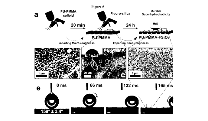
[00047] Figure 5: (a) diagram showing sequential deposition of micro- and nano-
roughness
onto substrates, conferring a tough, rubbery and mechanically durable
superhydrophobic
interface through self-assembled micro-structures. PU-PMMA interpenetrated
polymer network
(IPN) with micro and sub-micro structures, shown in (b) and (c) respectively.
(d) As deposited
nanostructures. (e) Ultrahydrophobicity demonstrated by a near 00 sliding
angle.
[00048] Figure 6: SEM analysis of crosslinked (a) PMMA, (c) PU and (e) PU-PMMA
IPNs
without F-SiO2 coating and (b,d,e) with F-SiO2 coating, respectively.
[00049] Figure 7: (a) Diagram showing functionalization of silica with
1H,1H,2H,2H-
perfluorooctyldimethylchlorosilane to produce fluoro-silica, with (b)
additional organic
signatures as highlighted by FTIR. Functionalization was further confirmed by
(c)
thermogravimetric analysis of the functionalized vs. control silica, measured
at 10 C/min under
nitrogen.
[00050] Figure 8: graphs demonstrating time-optimized abrasion-wetting
characterizations. (a)
WCAs, (b) SAs, (c) CAHs. Lag time for VOC degassing (i.e. drying) prior to
nanoparticle
deposition at 10 minutes.
CA 03024264 2018-11-09
WO 2017/193157 PCT/AU2017/000103
[00051] Figure 9: graphs demonstrating time-optimized abrasion-wetting
characterizations. (a)
WCAs, (b) SAs, (c) CAHs. Lag time for VOC degassing prior to nanoparticle
deposition at 30
minutes.
[00052] Figure 10: graphs demonstrating time-optimized abrasion-wetting
characterizations. (a)
WCAs, (b) SAs, (c) CAHs. Lag time for VOC degassing prior to nanoparticle
deposition at 40
minutes.
[00053] Figure 11: Optimization of VOC degassing (25 C, laboratory
environment: 50-60%
humidity, kept out of direct sunlight) analyzed through abrasion testing from
10 to 40 minutes.
At less than 10 minutes (e.g. 5 minutes), as-developed coatings were not
superhydrophobic.
[00054] Figure 12: (a) Transmittance of plain glass substrates vs. different
coating layers (at
600nm) and the optimized coating layer (inset of sample showcasing excellent
transparency).
Bi-layer PU-PMMA IPN, F-SiO2 coating on a variety of substrates, including (b)
absorbent
paper towel, (c) bricks (clay-stone), (d) wood (e) aluminium with minimal
hazing. In each of b
to e, the left hand sample is coated with a superhydrophobic coating according
to the invention,
and the right hand sample is uncoated.
[00055] Figure 13: UV-vis analysis of fluorosilica-coated glass and plain
glass at 600 nm.
[00056] Figure 14: photographs illustrating multi-substrate compatibility,
showing films
according to the invention on (a) cardboard, (b) writing paper, (c) glass and
(d) kapton
(polyimide). In each photograph, the left band sample is coated with a
superhydrophobic coating
according to the invention, and the right hand sample is uncoated.
[00057] Figure 15: (a) Tandem abrasion-wetting characterizations. Wetting
characterization of
cyclically abraded samples, with assessment of (c) static contact angles of PU-
PMMA-FSiO,
with PU-PMMA 1PN and F-SiO2 controls. SEM analysis at the loss of
superhydrophobicity
(WCA < 150 ) of (b) PU-PMMA-FSiO7, 300 cycles, with (d) high magnifications
showing the
persistent presence of nanoparticles. (e) Sliding angles and (f) contact angle
hystereses of F-
5i02 coated crosslinked PU, PMMA and PU-PMMA IPN revealed functionality damage
resilience of the latter.
CA 03024264 2018-11-09
WO 2017/193157 PCT/AU2017/000103
II
[00058] Figure 16: Tandem abrasion-wetting analysis for cross-linked polymeric
controls with
fluoro-silica deposition.
[00059] Figure 17: Low Magnification SEM images of (a-c) as-prepared and (d-f)
cycled-to-
failure (WCA < 150 ) interfaces ¨ (a,d) PMMA-FSi02, (b,e) PU-FSi02 and (c,f)
PU-PMMA-
FSi02 IPNs. (g) PMMA-FSi0/ at the point of failure (50 cycles). (h) PU-FSi07
at the point of
failure (150 cycles).
[00060] Figure 18: Intermediate cyclic damages of PU-PMMA-F-SiO2 coatings from
the 5th
cycle up to the 150th cycle, with negligible damages to the PU-PUMMA IPN-F-
SiO2.
[00061] Figure 19: Impacts of F-SiO2 coating and abrasion cycling on WLI-
measured root-
mean-square (rms) roughness at (a) 500 X magnification and (b) 200 X
magnification. rms
roughness measured at 500 X magnification revealed a nano-level impacted
interface, where
abrasion was noted to gradually decrease rms roughness, and thus
superhydrophobicity. No
trend was reasonably established at 200 X magnification, indicative of
negligible micro-level
impacts of abrasion on the interface.
[00062] Figure 20: Real-world radiation and chemical damage resilience. (a-b)
UV-C (254 nm)
resilience of F-SiO2 integrated PU-PMMA IPNs, with minimal observable impacts
on SA,
WCA and CAR during all 3000 minutes of testing. Immersion of F-SiO2 integrated
PU-PMMA
IPNs into (c) oil (tetradecane) and (d) acid (1M HC1) for 24 hours, with the
subsequent loss of
plastron layers in both, but demonstrated excellent damage resilience and
readily recovered
functionalities.
[00063] Figure 21: Stability of F-5i02 on glass under extended exposure to
high intensity UVC.
[00064] Figure 22: Reaction of (a) PU-PMMA hybrid pot to give a (b) sprayable
colloidal
suspension of PU-PMMA IPN solution. As-synthesized colloid is stable for at
least 6 months
without any signs of settling.
[00065] Figure 23: Contact angle vs. time as a water droplet (5 !IL) is added
to a
superhydrophilic surface according to the present invention.
Description of Embodiments
CA 03024264 2018-11-09
WO 2017/193157 PCT/AU2017/000103
12
[00066] The following abbreviations are used in the present specification:
CAH: contact angle hysteresis as measured using an advancing-receding contact
angle method
DD: dibutyltin dilaurate
IPN: interpenetrating polymer network
PMMA: polymethyl methacrylate
PTHF: polytetramethylene ether glycol (polytetrahydrofuran)
PU: polyurethane
SA: sliding angle or tilt angle
TDI: tolylene-2,4-diisocyanate
TRIOL: tris(hydroxymethyl)propane
WCA: static water contact angle as measured by the sessile drop method
[00067] The following terms used herein are defined as set out below:
hour half-life temperature: the temperature at which the half-life of a free
radical initiator is
10 hours.
Acrylic monomer: a monomer comprising a moiety of structure C=C-C=0.
IPN: Polymer comprising two or more networks that are at least partially
interlaced on a
molecular scale but not covalently bonded to each other and cannot be
separated unless
chemical bonds are broken (see IUPAC Gold Book
http://goldbook.iupac.org/I03117.html).
Superhydrophilic: having a WCA of less than about 100 achieved within 0.5s.
Superhydrophobic: having a WCA of at least 150 .
UVC: electromagnetic radiation in the frequency range 290-100nm.
[00068] The invention described herein relates to a suspension of colloidal
particles which
comprise an IPN, a process for making the suspension, and films made from the
suspension.
[00069] The process for making the suspension involves initially preparing a
polymerisation
mixture, which may be a solution and/or a dispersion. This mixture comprises
monomer systems
for the two interpenetrating polymers of the network. The monomer systems are
capable of
CA 03024264 2018-11-09
WO 2017/193157 PCT/AU2017/000103
13
polymerising using different mechanisms. The resulting network may be a
simultaneous IPN,
i.e. the two network polymers may form at the same time, or may be a
sequential IPN, i.e. a first
network polymer is formed and the second network polymer subsequently forms
within the first
polymer. It is thought that if a free-radical inhibitor is present in the
polymerisation mixture the
IPN will be predominantly sequential whereas if it is absent it will be
largely simultaneous.
[00070] A first monomer system is based on acrylic monomers and is
polymerisable by a free-
radical mechanism. This monomer system comprises a non-crosslinking monomer
comprising
only one carbon-carbon double bond and a crosslinking monomer comprising at
least two
carbon-carbon double bonds. The non-crosslinking monomer may be acrylic or
methacrylic. It
may be for example a (meth)acrylic ester, a (meth)acrylamide, (meth)acrylic
acid or some other
non-crosslinking acrylic monomer (e.g. an alkoxymethacrylic ester). The
crosslinking monomer
may similarly be a (meth)acrylic ester or a (meth)acrylamide. In the case of
an ester, it may be
an ester of a diol, a triol, a tetraol, a pentaol or some other polyol, i.e.
it may be a diester,
triester, tetraester or pentaester etc. In the case of an amide, it may have
structure HN((=0)C-
CH=CH2)2, N((=0)C-CH=CH2)3 or some other similar structure. The first monomer
system
includes a catalyst (free radical initiator) which is present in the
polymerisation mixture. The
catalyst may be an azo initiator, an azo ester initiator, a peroxide
initiator, a peroxydicarbonate
initiator or some other suitable initiator. Commonly it will be a thermal
initiator (i.e. one that is
activated by heating), however it may in some instances be a UV-activatable
initiator, a redox
initiator or some other suitable initiator type. In the event that it is a
thermal initiator, it may
have a 10 hour half-life temperature of between about 40 to about 80 C, or
about 40 to 70, 40 to
60, 50 to 80, 60 to 80 or 50 to 70 C, e.g. about 40, 45, 50, 55, 60, 65, 70,
75 or 80 C. It will be
recognised that the half-life of an initiator may be dependent in part on the
medium in which it
is measured. The above 10 hour half-life temperature may be as measured in
toluene, or may be
as measured in the polymerisation mixture. Suitable initiators include
azobis(isobutyronitrile)
(AIBN), 4,4-azobis(4-cyanovaleric acid), benzoyl peroxide, lauroyl peroxide
and potassium
persulfate.
[00071] The polymerisation mixture (optionally the first monomer system) may
also comprise a
radical scavenger or radical polymerisation inhibitor. This may for example be
a quinone type
inhibitor such as MEHQ (hydroquinone monomethyl ether). The inhibitor may be
supplied with
the non-crosslinking monomer or with the crosslinking monomer or with both. It
may be present
in sufficiently low concentration that during the free radical polymerisation
process it is entirely
CA 03024264 2018-11-09
WO 2017/193157 PCT/AU2017/000103
14
consumed by the free radical initiator. It may be present in the
polymerisation mixture at a mole
ratio to the free radical initiator of less than about 20%, or less than about
10 or 5%, e.g. at about
1, 2, 3, 4, 5, 10, 15 or 20 mol%.
[00072] In the first polymerisation system, the ratio of non-crosslinking
monomer to
crosslinking monomer on a mole basis of polymerisable groups may be from about
10 to about
50 (i.e. about 10:1 to about 50:1, or about 10 to 40, 10 to 30, 10 to 20,20 to
50, 30 to 50 or 15 to
30, e.g. about 10, 11, 12, 13, 14, 15, 16, 17, 18, 19, 20, 25, 30, 35, 40, 45
or 50. In this context,
for example, if the ratio of a non-crosslinking monomer to crosslinking
monomer on a mole
basis were 2 (i.e. 2:1) and the crosslinking monomer had two polymerisable
olefinic groups per
molecule (e.g. if it were a dimethacrylate), then the ratio of non-
crosslinking monomer to
crosslinking monomer on a mole basis of polymerisable groups would be 1:1. The
free radical
initiator may be present at a mole ratio of about 2% relative to the total of
non-crosslinking and
crosslinking monomer. It may be present at about 0.5 to about 5%, or about 1
to 5, 2 to 5, 0.5 to
2,0.5 to 1 or Ito 3%, e.g. about 0.5, 1, 1.5, 2, 2.5, 3, 3.5, 4, 4.5 or 5%.
[00073] A second polymerisation system is based on urethane chemistry, i.e. it
contains a diol, a
polyol and an isocyanate having at least two isocyanate groups per molecule.
The isocyanate
may for example be TDI (toluene diisocyanate, e.g. 2,4 or 2,6 or a mixture
thereof), MD1
(methylene diphenyldiisocyanate), IPDI (isophorone diisocyanate), HDI
(hexamethylene
diisocyanate), HMDI (hydrogenated MDI: methylene bis(4-cyclohexylisocyanate)),
naphthalene
diisocyanate, triphenylmethane-4,4',4"-triyltriisocyanate or some other
diisocyanate or
triisocyanate. It may be an aromatic isocyanate or may be an aliphatic
diisocyanate. In some
instances the isocyanate may have more than 2 isocyanate groups per molecule,
e.g. 3, 4 or 5.
The diol may be any suitable compound having two hydroxyl groups joined by an
organic
moiety. It may be an alkane diol (i.e. the organic moiety may be an alkanediyl
group, which may
be straight chain, branched, cyclic or may have two or all of these
structures), for example an
alkane a,co-diol in which the alkane is a straight chain alkane (i.e. it may
be HO(CH7),OH), in
which case n may be from 2 to 12, or 2 to 10, 2 to 6, 3 to 8 or 4 to 6, e.g.
2, 3, 4, 5, 6, 7, 8, 9, 10,
11 or 12, optionally greater than 12), or it may be a polyether polyether diol
(e.g.
HO(CH7CH70),H or HO(CH(CH3)CH70),H, in which case n may be from 1 to about 50,
or
about 1 to 20, a to 10, 1 to 5, 5 to 50, 10 to 50, 20 to 50, 5 to 20, 5 to 10
or 10 to 20, e.g. 1, 2, 3,
4, 5, 6, 7, 8, 9, 10, 15, 20, 25, 30, 35, 40, 45 or 50, optionally greater
than 50) or it may be some
other type of diol. The diol may have a molecular weight of between about 500
and about 5000,
CA 03024264 2018-11-09
WO 2017/193157 PCT/AU2017/000103
or 1000 to 5000, 2000 to 5000, 500 to 2000, 500 to 1000 or 1000 to 2000, e.g.
about 500, 1000,
1500, 2000, 2500, 3000, 3500, 4000, 4500 or 5000. It may have no other
functional group other
than OH. It may have no amine groups. It may have no carboxyl groups. It may
have no carbon-
carbon unsaturation (i.e. no double bonds or triple bonds). It may have no
groups that would be
polymerisable using free radical initiation. The polyol is any suitable
compound containing
more than two hydroxyl groups per molecule. It may have 3, 4, 5, 6, 10, 15, 20
or more than 20
hydroxyl groups per molecule. It may be a monomeric polyol or it may be
oligomeric. It may be
for example a saccharide, tris(hydroxymethyl)propane,
tris(hydroxymethyl)ethane,
pentaerythritol, erythritol or some other type of polyol. It may be an
aliphatic polyol. It may
have no carbon-carbon unsaturation (i.e. no double bonds or triple bonds). It
may have no
groups that would be polymerisable using free radical initiation. It may have
no other functional
group other than OH. It may have no amine groups. It may have no carboxyl
groups. It may be
monomeric.
[00074] The ratio of polyol to diol in the second polymerisation system may be
about 3 to about
10 (i.e. 3:1 to 10:1), or about 5 to 10 or 3 to 7, e.g. about 3, 4, 5, 6, 7,
8, 9 or 10 on a mole OH
basis. However since the polyol commonly has lower molecular weight than the
diol (since the
latter may be oligomeric), the weight ratio of polyol to diol may be about 0.1
to about 0.5, or
about 0.2 to 0.5, 0.3 to 0.5, 0.1 to 0.4, 0.1 to 0.3 or 0.2 to 0.4, e.g. about
0.1, 0.2, 0.3, 0.4 or 0.5.
The mole ratio of isocyanate to hydroxyl (on a functional group basis) may be
about 1, and may
be between about 0.7 to about 1.3, or about 0.7 to 1, Ito 1.3, 0.8 to 1, 1 to
1.2, 0.9 to 1, 1 to 1.1
or 0.8 to 1.2, e.g. about 0.7, 0.8, 0.9, 1, 1.1, 1.2 or 1.3. In some
embodiments, isocyanate is
present in molar excess over hydroxyl. It may be present in a molar excess of
about 1 to about
20%, or about 1 to 10, 1 to 5,5 to 20, 10 to 20 or 5 to 10%, e.g. about 1, 2,
3, 4, 5, 6, 7, 8, 9, 10,
15 or 20%. The polyurethane catalyst may be added at a concentration of about
100 to about
500ppm on a w/v (i.e. mg/L) or volume (i.e. micrograms per litre) basis
relative to the remaining
portions of the polymerisable mixture, or about 100 to 300, 300 to 500 or 200
to 400ppm, e.g.
about 100, 150, 200, 250, 350, 400, 450 or 500ppm.
[00075] The components of the first and second polymerisation systems
described above are
combined in a solvent. This may involve simply adding each of the components
of the two
systems to a solvent. In this instance, the solvent may be a solvent which
dissolves all of these
components. Suitable solvents are organic liquids and mixtures, preferably
homogeneous
mixtures, thereof. Thus when mixtures are used, the two or more liquids should
be miscible in
CA 03024264 2018-11-09
WO 2017/193157 PCT/AU2017/000103
16
the proportion in which they are used. Suitable solvents include toluene,
acetone, diethyl ether,
1,4-dioxane, benzene, ethyl acetate, glyme, diglyme and mixtures. In one
embodiment, the first
polymerisation system is prepared in a first solvent and the second
polymerisation system is
prepared in a second solvent (which may be the same as the first solvent or
may be different, but
should be miscible therewith) and the two resulting solutions are combined to
form the
polymerisation mixture. Other addition processes to produce the polymerisation
mixture will be
readily apparent.
[00076] The polymerisation mixture, as well as, independently, the solutions
of the first and
second polymerisation systems in the event that these are prepared and mixed
to form the
polymerisation mixture, may have a solids content of from about 5 to about 25%
w/v, or from
about 5 to 20, 5 to 15, 10 to 20 or 7 to 15%, e.g. about 5, 6, 7, 8, 9, 10,
12, 14, 16, 18, 20, 22, 24
or 25%. In this context, "solids content" refers to the weight of all
materials other than the
solvent in 100m1 of solution. Thus "solids" may in fact not be in solid form.
[00077] Once the polymerisation mixture has been prepared, a catalyst for
polyurethane
polymerisation is added. Suitable catalysts include metal based catalysts,
e.g. catalysts based on
tin, bismuth, zirconium, aluminium or mixtures of any two or more of these.
The catalyst may
be a carboxylate, e.g. a laurate, stearate, an acetate or some other
carboxylate. The metal may
also be bonded to one or more (commonly two) alkyl groups e.g. a Cl to C6
alkyl group.
Suitable catalysts therefore include dibutyltin dilaurate and dibutyltin
diacetate. Other catalysts
include tertiary amine catalysts such as 1,4-Diazabicyclo[2.2.2]octane
(Dabco),
diazabicyclononane (DBN), diazabicycloundecane (DBU), 2,2'-
bis(dimethylamino)diethylether,
benzyldimethylamine, N,N-dimethylcyclohexylamine etc. The resulting catalysed
reaction
mixture is then heated for a suitable time at a suitable temperature for
polymerisation of both
polymerisation systems. The temperature will depend on the precise nature of
the components of
the two systems. Typically, the temperature will be within about 10 C of the
10-hour half-life
temperature of the free radical initiator. It may be from about 30 to about 90
C, or about 30 to
70, 30 to 50, 50 to 90, 70 to 90 or 50 to 70 C, e.g. about 30, 35, 40, 45, 50,
55, 60, 65, 70, 75,
80, 85 or 90 C, but in some instances may be greater than 90 or less than 30
C. The time will
commonly be between about 50% and about 200% of the half-life of the initiator
or about 50 to
100, 100 to 150 or 150 to 200% thereof, e.g. about 50, 60, 70, 80, 90, 100,
110, 120, 130, 140,
150, 160, 170, 180, 190 or 200% of the half-life of the initiator. It may be
between about 5 and
about 20 hours, or about 5 to 10, 10 to 15 or 15 to 20 hours, e.g. about 5, 6,
7, 8, 9, 10, 11, 12,
CA 03024264 2018-11-09
WO 2017/193157 PCT/AU2017/000103
17
13, 14, 15, 16, 17, 18, 19 or 20 hours. In some instances, the polymerisation
temperature is
greater than the ambient pressure boiling point of the solvent, or of one of
the solvents. It may
be beneficial to conduct the polymerisation under increased pressure and/or in
a sealed container
(optionally a sealed pressure vessel). In some instances the polymerisation
mixture may be
degassed before polymerisation is initiated, so as to remove oxygen. This may
be achieved by
sparging, e.g. with nitrogen, helium or some other non-oxygen containing gas,
or may be
achieved by successive freeze-thaw cycles (e.g. 2, 3 or 4 such cycles) or by
any other suitable
method. In some instance the reaction may be conducted in the dark, i.e. with
exclusion of
visible light and/or with exclusion of UV radiation, optionally with exclusion
of all
electromagnetic radiation.
[00078] Following polymerisation to form an interpenetrating polymer network,
the network is
in the form of a dispersion of network particles in the solvent. It may be a
colloidal dispersion.
The particles of the dispersion may have a mean particle diameter of from
about 200 to about
1000nm, or from about 200 to 500, 500 to 1000 or 300 to 700nm, e.g. about 200,
250, 300, 350,
400, 450, 500, 550, 600, 650, 700, 750, 800, 850, 900, 950 or 1000nm. In some
cases, it may be
smaller, e.g. down to about 1 Onm. It may be for example about 10 to about
200nm, or about 10
to 100, 10 to 50, 20 to 200, 50 to 200, 100 to 200, 20 to 50 or 50 to 100nm,
e.g. about 20, 30, 40,
50, 60, 70, 80, 90, 100, 150 or 200nm. The particles may be monodispersed or
may be
polydispersed. They may have a broad or a narrow particle size distribution.
The ratio of weight
average to number average particle diameters may be between about 1 and about
10 or greater,
or about Ito 5, Ito 2,2 to 10,5 to 10 or 2 to 5, e.g. about 1, 1.5, 2, 2.5, 3,
3.5, 4, 4.5, 5, 6, 7, 8,
9 or 10. It will therefore be understood that the dispersion contains a cured
interpenetrating
polymer network in the form of colloidal particles dispersed in a solvent.
When this is applied to
a surface, the solvent can evaporate, leaving a surface having microroughness
due to the
colloidal particles.
[00079] The dispersion may be a sprayable dispersion. It may have a viscosity
less than about
1000cP, or less than about 500, 200, 100 or 50cP.
[00080] The dispersion may be applied to a surface so as to form a coating of
the
interpenetrating polymer network on the surface. The applying may comprise
spraying, wiping,
rolling, spin-coating, dip-coating, drop-casting, electrospinning, or some
other suitable method.
The process may further comprise allowing the coating to dry to form a dried
coating on the
CA 03024264 2018-11-09
WO 2017/193157 PCT/AU2017/000103
18
surface. The time for drying will depend in part on the vapour pressure of the
solvent and in part
on the temperature of the drying. The drying may be conducted at any suitable
temperature. It
will commonly be conducted at ambient temperature, e.g. between about 20 and
25 C, but may
be conducted at elevated temperature, e.g. about 25 to about 60 C, or about 25
to 50, 25 to 35 or
35 to 60 C. It may for example be conducted at about 20, 25, 30, 35, 40, 45,
50, 55 or 60 C.
Suitable conditions are 20-25C. 40-60% relative humidity. The surface may be
any suitable
surface. It may be a metallic surface, a polymeric surface, a wooden surface,
a glass surface, a
ceramic surface, a synthetic surface or some other surface. The resulting
dried film may function
as a protective coating. It may function as a base coat for further coating
layers.
[00081] In one embodiment, after partial drying of the coating, a particulate
material is applied
to the coating. Commonly the particulate material will be applied as a
suspension. It may for
example be sprayed onto the coating. The suspension may be in a volatile
solvent. It may be in
any of the solvents or any mixture there of listed above in respect of
preparing the polymerisable
mixture. The concentration of the particulate material in the suspension may
be about 1 to about
10% w/v, or about Ito 5, Ito 2,2 to 10,5 to 10 or 2 to 5%, e.g. about 1, 2, 3,
4, 5, 6, 7, 8, 9 or
10%. It is thought that the hydrophobic particles provide nanoroughness to the
surface of the
film, which, in combination with the microroughness due to the colloidal
particles, provides
superhydrophobicity.
[00082] The particulate material may be a particulate solid. It may have a
mean particle size of
about 2 to about 20run, or about 2 to 10, 2 to 5, 5 to 20, 10 to 20 or 5 to
lOnm, e.g. about 2, 3, 4,
5, 6, 7, 8, 9, 10, 11, 12, 13, 14, 15, 16, 17, 18, 19 or 20nm. It may be an
inorganic particulate
solid. Particles of the particulate solid may have organic regions and
inorganic regions. The
particulate solid may be hydrophobic. It may be a ceramic. It may be titan ia.
It may be iron
oxide. It may be a hydrophobic ceramic, e.g. hydrophobic silica. It may be a
silica having
grafted organic groups on the surface of the particles thereof. It may be a
fumed silica, e.g. a
hydrophobic fumed silica. Mixtures of any two or more of these particles may
also be used. It
may be a fumed silica having hydrophobic groups on the surface. The
hydrophobic groups may
be alkyl groups, e.g. C I to C18 straight chain or branched alkyl groups, such
as methyl, ethyl, n-
propyl, i-propyl, n-butyl, t-butyl, hexyl, octyl, isooctyl, decyl, dodecyl,
tetradecyl or hexadecyl.
They may be fluoroalkyl groups, e.g. perfluoalkyl groups. They may be
fluorinated or
perfluorinated or partially perfluorinated forms of any of the alkyl groups
described above. Any
two or more of the above hydrophobic groups may be present. For example, the
fumed silica
CA 03024264 2018-11-09
WO 2017/193157 PCT/AU2017/000103
19
may have fluoroalkyldialkylsilyloxy groups on the surface. The alkyl groups
may be any of the
alkyl groups described above, and the fluoroalkyl group may be any of the
fluoroalkyl groups
described above. For example the particulate solid may comprise fumed silica
having
1H,1H,2H,2H-perfluorooctyldimethylsiloxy groups on the surface thereof. It
should be noted
that "1H,1H,2H,2H-perfluorooctyl" refers to F3C(CF2)5(CH2)2-. The organic
groups may be
present on substantially the entire surface of the particles. The hydrophobic
particulate solid,
when applied to the film, may be partially wetted by the polymer mixture or it
may be
completely wetted by the polymer mixture. The particles of the particulate
solid may be wetted
over a part of their surface. The particulate solid may be wetted before
curing and/or drying of
the polymers such that, when cured, the hydrophobic solid is at least
partially embedded in the
surface of the film. The embedded particles may be abrasion resistant. The
embedded particles
may be partially embedded in the surface of the film and partially exposed to
the surrounding
environment or they may be fully embedded in the surface of the film.
[00083] Alternatively the particulate solid applied to the film may be
hydrophilic. It may be a
hydrophilic ceramic. It may be for example a hydrophilic silica, e.g.
colloidal silica or fumed
silica, or it may be a hydrophilic (e.g. colloidal) titania, alumina, zirconia
or other suitable
hydrophilic solid. Following complete drying, the resulting film may be
superhydrophilic. It
may have a WCA of less than about 100, or less than 9, 8, 7, 6, 5, 4, 3, 2 or
1 . It may have a
WCA of about 1, 2, 3, 4, 5, 6, 7, 8, 9 or 100, or may have a substantially
zero contact angle. It
may achieve this within about 0.5s, or within about 0.4, 0.3, 0.2 or 0.1s of
application of the
droplet to the surface of the film. In the superhydrophilic film, the
hydrophilic particles may be
wetted by the polymer of the film. It is thought that this might occur by
virtue of the particles
being applied in a suspension of an organic solvent. Thus as a droplet of
solvent containing one
or more hydrophilic particles impacts on the surface of the film, which
contains residual water,
the solvent can blend with the film, possibly by blending with the water, and
thereby lead to
wetting of the hydrophilic particles by the film.
[00084] Once a hydrophilic solid has been added to the film, it may be
subsequently
hydrophobed. This may be achieved by exposing the film, and/or the hydrophilic
particles, to a
hydrophobing agent. The same range of hydrophobing agents as is described
elsewhere herein
may be used. This may result in a superhydrophobic film as described elsewhere
herein.
CA 03024264 2018-11-09
WO 2017/193157 PCT/AU2017/000103
[00085] The suspension of the particulate material and the dispersion of
network particles may
each be stable. They may, independently, be stable for at least about 1 week
or at least about 2,
3, 4, 5, 10, 15, 20, 25, 30, 35, 40, 45 or 50 weeks. In this context, the term
"stable" indicates that
after the stated period, the concentration of particles in the top half of the
dispersion differs from
the concentration of particles in the bottom half of the dispersion by less
than about 10%, or less
than about 8, 6, 4, 2 or 1%, when the dispersion is stored without agitation.
[00086] The particulate solid may be applied to the coating after a delay time
(following
application of the coating to the surface) of from 10 to about 100 minutes, or
about 10 to 50, 10
to 20, 20 to 100, 50 to 100, 10 to 40, 10 to 30 or 20 to 40 minutes, e.g.
about 10, 15, 20, 25, 30,
35, 40, 45, 50, 55, 60, 65, 70, 75, 80, 85, 90, 95 or 100 minutes. The time
should be sufficient
for partial drying but preferably insufficient for complete drying of the
coating. Following
application of the particulate solid, the resulting composite solid may be
allowed to dry
completely. In this context "completely" indicates a residual solvent content
of less than about
5% by weight, or less than about 4, 3, 2 or 1% by weight.
[00087] The resulting composite film may therefore comprise an
interpenetrating polymer
network, and may have a surface layer comprising the particulate solid. In
this context, the
"surface layer" may be the top 20% of the film, or the top 10%, or the top 5%
or the top 2%.
The surface layer may comprise both the interpenetrating polymer network and
the particulate
solid. It may comprise the particulate solid at least partially embedded in
the interpenetrating
polymer network. The composite network may be hydrophobic. It may be
superhydrophobic. It
may be a lotus effect surface. It may exhibit Cassie-Baxter wetting
characteristics. It may have a
WCA of at least about 150 , or at least about 155, 160 or 165 , e.g. about
150, 155, 160, 165 or
170 C. It may have a sliding angle of less than about 20 , or less than about
15, 10 or 5 , e.g.
about 5, 10, 15 or 20 . It may be capable of maintaining these values after
abrasion. It may be
capable of maintaining these characteristics after at least 50 abrasion
cycles, or after at least 60,
70, 80, 90, 100, 150 or 200 abrasion cycles. These may be as defined in ASTM
D4060-14. It
may be capable of maintaining these characteristics after at least 1000
minutes of UV exposure
at 354nm and 3.3mW/cm2, or at least about 1500, 2000, 2500 or 3000 minutes. It
may be
capable of maintaining these characteristics after at least 6 hours of
immersion in a strong
mineral acid, or at least 12, 18 or 24 hours. It may be capable of maintaining
these
characteristics after at least 6 hours of immersion in oil, or at least 12, 18
or 24 hours. The film
may be substantially transparent to visible light at a thickness of up to lmm.
It may have
CA 03024264 2018-11-09
WO 2017/193157 PCT/AU2017/000103
21
transmittance at 600nm of at least about 50%, or at least about 55, 65 or 70%.
The film may
have a thickness of from about 10 to about 50 microns (micrometres), or about
10 to 30, 20 to
50, 20 to 30 or 20 to 40 microns, e.g. about 10, 15, 20, 25, 30, 35, 40, 45 or
50 microns.
[00088] The superhydrophobic films of the present invention may be used in any
application in
which superhydrophobicity is a benefit and/or where abrasion resistance and/or
durability is a
benefit. For example they may be used to reduce drag coefficient in water
craft, or to reduce
marine fouling, or to reduce corrosion of bodies, especially metallic bodies,
immersed in water.
They may also be used as coatings on electronics, solar panels, on glass
surfaces to reduce
droplet adhesion (e.g. for windscreens), in medical equipment, for rendering
surfaces self-
cleaning and in other applications. The superhydrophilic films of the
invention may be used in
any application in which superhydrophilicity is a benefit and/or where
abrasion resistance and/or
durability is a benefit. For example they may be used in antifogging screens,
windows and
lenses, anti-fouling coatings, microfluidic devices, biocompatible implant
devices, coatings for
enhanced boiling heat transfer, foils for food packaging etc. Additionally,
the films of the
invention, whether superhydrophilic, superhydrophobic or otherwise, form a
useful protective
coating to substrates to provide improved resistance to abrasion and to
chemical insults.
[00089] In a particular embodiment, the invention relates to a stable PU-PMMA
colloidal IPN
system that self-assembles during spray deposition into a hierarchically
structured ultra-robust
coating. This IPN coating serves as a platform for superhydrophobic
nanostructures enabling
preservation of a highly dewetting Cassie-Baxter state through mechanical-,
chemical- and
photo-induced stresses. These superhydrophobic coatings preserved a pristine
lotus-dewetting
surface (WCA > 150 , SA < 10 ) after 250 rotary abrasion cycles, finger-wipe
resilience,
extended immersion in concentrated acids and oil contamination as well as
extended high
intensity UVC exposure. Furthermore, the composite interfaces possess
excellent optical
properties with 14.8% net transmittance losses. The findings provide an easily
applicable PU-
PMMA IPN platform with superior mechanical and chemical properties for the
synthesis of
highly durable and transparent self-cleaning coatings, an enabling step for
many real-world
applications.
[00090] Described herein is a method for the fabrication of ultra-durable
sprayable
superhydrophobic coatings, based on micro-nano texturing of hybrid
interpenetrated polymer
networks (IPNs). A sprayable polyurethane-acrylic colloid is developed that
enables rapid self-
CA 03024264 2018-11-09
WO 2017/193157 PCT/AU2017/000103
22
assembly of complex surface structures, comprising soft yielding marshmallow-
like pillars
textured by sub-micron craters. The spray-developed IPN possessed excellent
optical properties
with less than 5% light transmission losses. Coupled with a superhydrophobic
nanoparticulate
layer, the composite IPN demonstrated outstanding anti-abrasion resistance,
preserving
superhydrophobic water contact angles and pristine lotus effect with sliding
angle below 100 for
up to 120 continuous standard abrasion cycles (ASTM D4060). The composite IPN
was also
chemical- and photo-stable, with excellent preservation of superhydrophobic
dewetting
properties upon exposure to 50 h of intense UVC light (254 nm, 3.3 mW.cm12),
24 h of oil
contamination and highly acidic conditions (1M HC1). These findings provide a
set of syntheses
and structural parameters for the engineering of highly performing durable
superhydrophobic
coatings with superior abrasion, chemical and UV-resistance.
Examples
Discussion
Solvent-borne synthesis of sprayable interpenetrated poly-urethane -acrylic
networks
[00091] The synthesis of the sprayable IPN hierarchical textures is
illustrated in Figure la. The
IPN solution was prepared in 2 parts, with an acrylic-based (PMMA) component
in acetone and
a polyurethane-based (PU) component in xylene. Upon mixing both parts, the
simultaneous
cross-linking of PMMA and PU components results in a colloidal suspension of
PU-PMMA that
readily self-assembles into hierarchically structured IPN during spray-
deposition. The cross-
linking of the acrylic component is thought to form dispersed constituents
within the much
more rapidly developed polyurethane networks, stabilizing the continuous PU
phase, which
eventually enables a toughened interface through interlaced networks.
Spectroscopic analysis of
the spray-developed coatings (Figure lb-d) indicates complete polymerization
of both the PU
and PMMA components. Complete PU reaction is confirmed by the loss of the 2235
cm-I
N=C=O isocyanate stretch band (Figure 1c) and 3227 cm-I and 3492 cm-I ¨OH
stretch bands
belonging to polytetramethylene ether glycol (PTHF) and
tris(hydroxymethyl)propane (TRIOL),
respectively, and by the formation of the 3300 cm-I ¨NH stretch band (Figure
lb). Complete
PMMA reaction is revealed by a loss of the 1 637 cm-I C=C stretch band, which
is the main
chemical signature of methyl methacrylate (MMA) and its crosslinker (Figure
id).
CA 03024264 2018-11-09
WO 2017/193157 PCT/AU2017/000103
23
Thermomechanical analysis of interpenetrated networks
[00092] Homopolymeric PU and PMMA were also developed as cross-linking (Figure
2a,b)
sprayable control samples (Figure 3). It is notable that purely cross-linked
PMMA developed in
this solvent system (xylene: acetone), were not sprayable (0.488 ¨ 0.600
polymer to solvent
ratios). Mechanical behavior of the as-sprayed IPNs (Figure 2c,d) and the
controls coatings were
observed and measured by stress-strain analysis using a tensile tester
(Instron 4505, U.S.A). The
spray-casted control PMMA samples were hard to manipulate upon due to their
brittle nature,
and thus were liquid-cast (Figure 2d). A direct comparison between the IPN and
the control
samples revealed much enhanced stiffness in the former (Figure 2d). This is
shown by a two-
fold increase in the Young's modulus, from 86.9 MPa of the PU to 192 MPa of
the IPN. The
maximum tensile strength was increased by nearly 11 times, from 1.5 MPa of the
PU to 16 MPa
of the IPN. Despite the significantly higher stiffness, the IPN was also
significantly toughened
and able to absorb much more energy up until fracture. The IPN showed an
increase of
approximately 32 times in elongation at break, from 5.5% of the PU to 179-210%
of the best
IPN samples. This sprayable IPN exceeds the properties of commercially
available elastomers,
for example, polydimethylsiloxane (PDMS), Sylgard 184.
[00093] Thermal analysis of the samples by differential scanning calorimetry
(DSC) supported
the finding of a well-formed interpenetrated network in the PU-PMMA IPN
system. Notably,
heat flow characteristics such as melting temperature (Tm), glass transition
(Tg) and thermal
curing (Tnm) were completely eliminated (Figure 2e). The mobility of the
pendant soft segment,
PTHF (Figure 2e), indicated by the Tg of -75 C and a T. of 145 C disappeared
in the
crosslinked PU and the IPN. The crosslinked pure PMMA showed a Tg of 60 C and
a final
curing reaction Tr,m at 145 C. However, upon integration of the acrylic
components into the
simultaneously curing PU-PMMA, these key thermal characteristics were
suppressed and a
nearly perfect constant heat flow was observed from -100 C up to 250 C for the
IPN (Figure
2e and Figure 4b). The disappearance of characteristic heat flow properties
from the former
components is indicative of mobility-restriction and a well-integrated 1PN
with ideally entangled
networks. These findings were further confirmed by the high temperature
thermogravimetric-
DSC (TG-DSC) analysis of crosslinked controls and IPN samples from 50 C to
900 C (Figure
4a-b). Beyond 200 C, decomposition at 50% weight losses, T50, were also noted
at 320 C
(PU), 333 C (PU-PMMA) and 378 C (PMMA), respectively, with the IPN showing
combined
properties of crosslinked samples. These thermal properties are in support of
the well-integrated
CA 03024264 2018-11-09
WO 2017/193157 PCT/AU2017/000103
24
IPNs. Further confirmation of successful IPN synthesis was conducted via
immersion of thin (23
pm) strips of material in parent solvents (acetone, xylene) as well as harsher
solvents
(chloroform, tetrahydrofuran), all of which were insoluble over a period of 24
hours. Thin
coated coatings were notably not soluble in parent solvents (acetone, xylene)
while being
swelled significantly in much stronger solvents (THF and chloroform).
Ultra-hydrophobic hierarchical interfaces
[00094] The PU-PMMA IPN's microroughness (RI) (Figure 5a-c) was higher
(Figure 6) than
that of the spray deposited homopolymeric PU and PMMA controls (Figure 6).
White light
interferometry (WLI, 200x) revealed that the cross-linked PMMA and PU had a
root-mean-
square (nns) roughness (Rq) of 238 47 nm and 2467 102 nm, respectively.
The PU-PMMA
IPN showed increased nns roughness of 3048 398 nm. Despite its lower Rq, the
crosslinked
PU had a similar microscale hierarchy to the PU-PMMA IPN (Figure 6),
indicating its
dominance as the hybrid's continuous phase of the IPN. The main difference was
the presence
of surface sub-micro defects in the cross-linked PU (Figure 6). Furthermore,
high magnification
SEM images (Figure 5b) revealed the presence of extensive sub-micro craters
(diameter of 421
99 nm) on the hierarchical PU-PMMA IPN's surface. Surface energy analysis
(Figure 5c inset
and Figure 6 insets) through contact angle measurements indicate the co-
existence of PMMA
(WCA = 76 0.6 ) and PU (WCA = 101 1.4 ) on the as-developed IPN's
interface (WCA =
81 0.6 ).
[00095] An ideally performing superhydrophobic interface was synthesized
(Figure 5a), through
the spray-deposition of fluoro-functionalized silica (F-5i02) as described in
the Experimental
Section (Figure 7). Deposition of the functional F-5i02 layer onto the micro-
nano hierarchical
IPNs resulted in enhanced nanoroughness (Rw) from 1235 85 nm to 2420 120
nm at WLI,
500x and ultra-low surface energy. An optimal delay of 20 minutes after
deposition of the PU-
PMMA was found to improve particle encapsulation through optimized volatile
organic content
(VOC) degassing (Figure 5a). In this context, "degassing" refers to allowing
the volatile
materials to evaporate. This optimum deposition timeframe was confirmed via
optical
microscopy of the interface with respect to time and cyclic abrasion
optimization (Figure 8-11).
VOC degassing was optimised (25 C, laboratory environment (50-60% humidity),
kept out of
direct sunlight), and was analyzed through optical microscopy from 0 minutes
to 18 hours. The
largest morphological changes from an agglomerated coating (0 mins) to a micro-
bulbous
CA 03024264 2018-11-09
WO 2017/193157 PCT/AU2017/000103
coating (marshmallow-like) took place between 20 to 40 minutes, in close
alignment with the
optimal abrasion-resilience domains. The resulting composite IPN (PU-PMMA-
FSi02) had an
extremely superhydrophobic wetting properties with a near-undetectable sliding
angle of ca. 00
(Figure 5e).
Transparency and Substrate Independency
[00096] The transmittance spectra of the PU-PMMA-FSi02 layers and PU-PMMA are
shown in
Figure 12a against plain glass. At a wavelength of 600 nm, the net loss in
transmittances were
measured at 5.0 and 14.8% for the F-SiO2, PU-PMMA and PU-PMMA-FSiO, surfaces,
respectively. The transmittance drops between PU-PMMA-FSi02 from PU-PMMA were
non-
linearly compounded (Figures 12a and 13), and can be attributed to the
decoration of the PU-
PMMA interface with the F-SiO2, resulting in higher refractive index contrasts
at the interface.
This 14.8% transmittance loss did not affect the optical transparency of
glass, with printed text
and images clearly visible when placed directly behind the PU-PMMA-FSi07
coated glass
slides (Figure 12a). The substrate-independent self-assembly of the PU-PMMA-
FSi02 surfaces
was demonstrated on a multitude of materials, namely absorbent paper towel,
clay-stone based
bricks, wood and aluminum (Figure 12b-e and 14). The PU-PMMA formulation was
also
broadly applicable, and demonstrated compatibility with flame-made
superhydrophobic
coatings, achieving stabilization of these ultra-fragile fractal-like
structures.
Robust Superhydrophobicity and Long-Term Surface Damage Analysis
[00097] Tandem wetting-abrasion analysis (Figure 15a) of the PU-PMMA-FSiO,
surfaces
highlighted the drastic enhancement in mechanical stability over the PU, PMMA
and pure F-
SiO, layers used as controls. The pure layers of F-SiO2 deposited on the same
glass substrates
had an initial WCA of ca. 158 but lost their superhydrophobicity after merely
5 cycles,
resulting in a WCA of 101 80 and revealing extensive layer wear-through
(Figure 15a). In
stark contrast, the PU-PMMA-FSi02 interfaces preserved superhydrophobicity
with WCA >
1500 for up to 250 cycles, revealing a mere WCA drop to 143 6 after the
300th cycle (Figure
15a). This is in good agreement with the performance of the bare monolayers of
PU-PMMA.
These bare IPN layers preserved their inherent hydrophilic wetting properties
with a WCA of ca.
80 - 88 during the entire 300 cycles of abrasion, with no wear-through nor
any other visible
damage (Figure 15a). The other hierarchical support structures provided by
cross-linked PMMA
CA 03024264 2018-11-09
WO 2017/193157 PCT/AU2017/000103
26
and PU controls further highlighted the importance of integrating the soft
rubbery polyurethane
with the polyacrylic component (Figure 16). PMMA supported F-SiO2 layers
experienced a
rapid sharp drop in WCA, losing superhydrophobicity after only 10 cycles with
WCAs dropping
to 131 4 . After 40 cycles of abrasion, complete wear-through was observed
with WCAs
reaching 78 7 (Figure 16). The PU controls supported F-SiO2 layers
performed better, with
excellent preservation of superhydrophobicity until extensive wear-through
occurred at 100-140
cycles (Figure 16). For these PU-FSiO, surfaces, a sharp drop in WCA occurred
during the 100th
to 120th cycle from 165 3 to 115 24 that was mirrored by steep SA
increments from 37
50 to 81 100
.
[00098] Sliding angle analysis (Figure 15e) of the PU-PMMA-FSiO, coatings
revealed robust
preservation of a pristine lotus effect with SA below 100 for up to 120
cycles, with a slow but
continued rise in SA with increasing abrasion cycles up to 300 cycles. This
was indicative of
excellent elastic properties of the hierarchical structure that were capable
of particle retention
and resilient to extended abrasive damage. These results were supported by CAH
analysis,
depicting a smaller drop in dewetting properties per abrasion cycle as
compared to PU-FSi02
and PMMA-FSiO, variants (Figure 150. At high SEM magnification the abraded PU-
FSi07 and
PMMA-FSiO) surfaces revealed evidence of coating tears at the 50 and 150
abrasion cycles,
respectively. Although the casted PMMA coatings were notably rubbery during
tensile testing
(Figure 2d, the failure mode of spray-deposited acrylic coatings revealed
unmistakable brittle
fracturing distinguished by sharp edges (Figure 17d,g). The damaged PU
surfaces, instead, were
in line with the typical failure mode of rubbery materials, with plastic
yielding failure
characteristic of ductile fracture (Figure 17h). The remaining shreds of PMMA-
based coatings
were sporadically smooth, with a limited presence of the functional F-5i02
layer. The ease of
delamination between the PMMA and F-5i02 interfaces explain the rapid loss of
superhydrophobicity upon abrasion damage (Figure 17g). In contrast, the PU-
based surfaces had
better particle retention capabilities than PMMA, with a noticeable particle-
loaded surface even
along fracture lines (Figure 17h). However, the ductile fracturing of these PU
surfaces
eventually led to patchy wear-through and loss in functionality by the 150th
cycle (Figure 17e,h).
[00099] As a result, the superior mechanical properties of the PU-PMMA are
attributed to the
successful integration of the particle retention capabilities of PU, a soft
yielding material
interface, into the hybrid PU-PMMA IPN This gave rise to a tough but ductile
interface that
was capable of yielding under stress while retaining the key functional
nanoparticle layer
CA 03024264 2018-11-09
WO 2017/193157 PCT/AU2017/000103
27
without fracture. The interlacing of PMMA's crystalline polymeric network
preserved the
integrity of the IPN, and vastly promoted wear resistance, permitting the well-
sustained
damages without wear-through. Notably, high magnification SEM analysis of the
PMMA-PU
after 300 abrasion cycles (Figure 15b,d) only revealed minimal ironing of the
F-SiO2 functional
layer, which accounts for the highly water repulsive surface properties
(Figure 15d inset).
However, randomly scattered gouges and scratch-induced tears were present by
the 300th cycle
(Figure 17f and 18), which eventually resulted in the loss of
superhydrophobicity. Efficiency of
particle retention, mapped through WLI nanoroughness (Rq2) was estimated
across abrasion
cycles, demonstrating a gradual drop down to 1.28 0.01 [tm (Figure 19a).
This accounts for
the flattening of the nano- and micro- F-SiO2 agglomerates that were initially
detected by WLI.
However, microroughness (Rq) analysis (Figure 19b) suggests a generally well-
preserved micro-
level roughness under the now dense F-SiO2 layers, with minimal variation
before and after
abrasion, indicating excellent stability of the sub-layered micro-rough
marshmallow-like
structures (Figure 5c,e). The combination of excessive surface ironing and
microscopic tears in
the hybrid IPN eventually resulted in the flat, but a highly hydrophobic
coating after 300
abrasion cycles.
[000100] Touch resilience, UV, acid, and oil contamination resilience
[000101] The superhydrophobic PU-PMMA-FSi02 coatings were tested for various
real-world
applications and damage tests. These included the finger-wipe test, UV-
exposure, acid-exposure
as well as oil contamination. The finger-wipe test clearly demonstrated the
finger-touch
resilience of the PU-PMMA supported F-SiO2 coating as compared to the bare F-
SiO2 coating,
with full functional dewetting properties after a real-world5 damage
situation. These coatings
demonstrated superiority to the current state-of-the-art finger-wipe tested
resistant coatings that
are optically non-transparent due to the use of a highly concentrated
composite paint-like
system.
[000102] UV-exposure tests (UV-C, 254 nm, 3.3 mW cm-2) were also conducted up
to 50 h,
without any discernible changes in SA or WCA measurements (Figures 20a and
21). The
measured CAHs (Figure 20b) were also very stable and within the standard batch-
to-batch
variations ( 50). This demonstrates the negligible losses in dewetting
functionality that may
arise from the degradation of the IPN under intense UV exposure and its
superior photochemical
stability over other surfaces. Lastly, 24 h extended immersion into an oil
analog (n-tetradecane)
CA 03024264 2018-11-09
WO 2017/193157 PCT/AU2017/000103
28
(Figure 20c) and concentrated acid (1M HC1) (Figure 20d) resulted in minimal
impact on the
superhydrophobicity of the PU-PMMA-FSi02 interfaces. The acid-resistance
easily matches
performance demonstrated by current state-of-the-art acid-resistant
superhydrophobic coatings.
The ease of oil-decontamination was also demonstrated using a jet of ethanol
after retrieval.
This is of significant impact as infiltration of oil into superhydrophobic
materials is typically
expected to cause micro-reorganization, resulting in smoother surfaces while
impeding recovery
of superhydrophobicity. These findings are superior to the state-of-the-art
superhydrophobic
materials/coatings designed for these applications.
[000103] Fig.23 illustrates a superhydrophilic surface according to the
present invention. Thus
in Fig. 23 at the bottom is a series of photographs showing a 5 microlitre
droplet of water being
applied to the surface. At the time that the droplet makes contact (Oms), it
spreads rapidly to a
surface film with negligible contact angle.
Experimental Section
Polyurethane-acrylic (PU-PMMA) Colloid Preparation
[000104] A cross-linking polymethyl methacrylate mixture (Pot A) was first
prepared with the
addition of 10 mL of acetone (Sigma Aldrich, > 99.5%), followed by 1.01 mL of
methyl
methacrylate (Sigma Aldrich, 99%), 47.2 L of trimethylopropane
trimethacrylate (Sig-ma
Aldrich, 90%) and 30.4 L of 2,2'-azobis(2-methylpropionitrile) solution
(Sigma Aldrich, 0.2M
in toluene). Almost simultaneously, a cross-linking polyurethane mixture (Pot
B) was also
prepared with the addition of 10 mL of m-xylene (Univar, 99%), followed by
0.220g of 1,1,1-
tris(hydroxymethyl)propane (Sigma Aldrich, >98%), which was stirred rapidly
(1500 RPM) for
minutes to disperse the solids. 1.01 mL of polytetramethylene ether glycol
(Sigma Aldrich, Mõ
about 2000) was added and the resulting mixture allowed to under further
stirring for 5 minutes.
0.568 mL of tolylene-2,4-diisocyanate (Sigma Aldrich, 95%) was then added into
the mixture of
(poly)ols. The PTHF and TDI were first melted in a drying oven before
addition. Pot A was then
vortex mixed and poured directly into Pot B, forming the reaction Pot C, which
was clear. An
initiator, dibutyltin dilaurate (Sigma Aldrich, 95%, 5 microlitres) was then
added into Pot C
before the reaction was sealed and allowed to commence at 60 C for 24 hours
in darkness with
a constant stirring rate of 500 RPM to form a sprayable colloidal dispersion
(Figure 22). Excess
isocyanate groups were added to compensate for its high reactivity that is
known to lead to some
CA 03024264 2018-11-09
WO 2017/193157 PCT/AU2017/000103
29
side networking reactions. The post-reaction mixture is known as the sprayable
PU-PMMA
colloid (0.15 g mL-1), which is made up of 66 w/w PU and 34 w/w PMMA.
Homopolymeric
cross-linked polyurethane and polymethyl methacrylate controls (Figure 6) were
prepared under
identical reaction conditions, utilizing the same solvent, crosslinkers and
initiators (AIBN and
DD) ratios while excluding the constituents of the other polymer. Due to
fundamentally
different reaction environments (without its partner polymer), optimal spray-
reaction conditions
varied slightly, with pure PU being synthesized at 0.075 g mL-1 while PMMA was
synthesized
at 0.4 g mL-1. This was performed based on sequential concentration-
spectroscopic analysis,
aimed at the synthesis of a fluid prepolymeric solution while avoiding
gelation. Spray deposition
was conducted within 48 hours of reaction stoppage for all samples in efforts
to preserve
comparative consistency.
Functionalization of Silica Nanoparticles for F-5i02
[000105] A round bottom flask was first charged with 80 mL of dry chloroform
(Sigma Aldrich,
> 99%) and purged with dry nitrogen for 30 minutes. 2 g of fumed silica
nanoparticles (Sigma
Aldrich, 7 nm) with an effective surface area of 395 m2 g -1 were then added
into the flask under
gentle stirring with a further nitrogen purge of 10 minutes. At a graft
density of 4 [tmol
0.945 mL of 1H,1H,2H,2H-Perfluorooctyldimethylchlorosilane (Novachem) was
added into the
flask. Reaction was then allowed to proceed at 25 C at a stirring rate of 500
RPM for 48 hours
in an oil bath. Functionalized silica (F-SiO2) were then washed in 3 cycles of
dry chloroform (50
mL g1) and dried in a convection oven at 50 C for 24 hours. Fluoro-silica was
re-suspended in
acetone (Sigma Aldrich, > 99.5%), at a concentration of 50 mg mL-1 by
immersing the 5-10 mL
suspension in a sonication bath for 60 minutes with 15 minute intervals of 10
s long vortex
mixing. Spectroscopic analysis confirmed the successful functionalization
through the formation
of peaks from 500 cm-1 to 1000 cm-1 indicative of CF, groups (Figure 7).17
Thermogravimetric
analysis indicates a functionalized w/w percentage of ca. 19.5% (Figure 7).
Spray Coating of Polyurethane-acrylic IPNs
[000106] Upon completion of synthesis, liquid-based solutions of the
superhydrophobic (F-
5i0/) and optimized bottom coats (PU-PMMA IPN) can be stored for extended
periods (6
months) without losses in functional properties. As developed sprayable PU-
PMMA colloids
were sprayed at a pressure of 2-3 bars at a flow rate of 0.2 mL s-1 from a 10
cm working
CA 03024264 2018-11-09
WO 2017/193157 PCT/AU2017/000103
distance (WD) using an artist's air brush. 5 mL of the pre-polymer mixture
(0.15 g mL-I) was
typically sprayed onto glass substrates with an area of 2.5 cm by 10 cm. A
traverse rate of ca. 10
-1
cm s is maintained using guide rails on a custom-built spray rig. Optimized
sprayable
conditions of controls were calibrated (PU, 10 mL, 10 cm WD and PMMA, 1.25 mL,
15 cm) so
as to equalize the net deposition mass. Optimized coatings (23 i.tm thick, 5
mm width, 25 mm
length) of PU-PMMA IPNs were immersed (5 mL) into its parent solvents (acetone
and xylene)
and two other harsh solvents (THF, chloroform) for 2 hours and imaged. These
coatings were
observed to be insoluble over a period of 24 hours, with minimal swelling when
contacting its
parent solvents. Notably, they were also insoluble in THF and chloroform,
although significant
swelling of the coatings occurred, and they broke up mechanically upon
swirling. The post-
deposition insolubility in harsh solvents is characteristic of successfully
developed
interpenetrated polymeric networks.
Spray coating of F-5i02
[000107] F-5i07 in acetone suspensions (50 mg mL-I) were sprayed onto desired
(coated or
uncoated) substrates at 2-3 bars at a flow rate of 0.2 mL s-I from a 10 cm
working distance using
an artist's air brush. 2 mL of the suspension was typically sprayed onto
coated glass substrates
with a dimensional area of 2.5 cm by 5 cm. A traverse rate of ca. 10 cm s-I is
maintained using
guide rails on a custom-built spray rig. The VOC degassing time prior to the
deposition of
fluoro-silica was varied and briefly studied between 10 to 40 minutes in
optimally developed
samples. All coatings were stored for between 24-72 hours in darkness prior to
commencement
of tests. This enables complete curing, degassing and stabilization of intra-
polymer stresses
within the material prior to characterizations.
Wetting Analysis
[000108] Static water contact angles (WCAs) were measured by placing and
averaging 4 drops
of deionized water (6.5 [1.1_,) on cross-batch (4) sample surfaces using the
sessile drop method.
Superhydrophobic interfaces demonstrating a sliding angle (SA) with negligible
tilt were
classified under the SA of 0 . Abrasion damaged interfaces possessed higher
SAs were analyzed
via a custom-built tilting goniometer. The contact angle hysteresis (CAH) was
measured via the
drop-in drop-out technique which provided the average advancing contact angle
(ACA) at 9 I-
and the average receding contact angle (RCA) at 2 L. 4 cross-batch readings
were taken.
CA 03024264 2018-11-09
WO 2017/193157 PCT/AU2017/000103
31
Dynamic and static images were recorded using a KSV CAM200 contact angle
goniometer
(Finland) with a heliopan ES43 camera (Japan). The CA, SA and CAH were
computed by a
commercially available (CAM2008) program. Data was presented as mean
standard errors.
Abrasion Analysis
[000109] Quantitative abrasion damage analysis was conducted using a rotary
platform abrasion
tester with two abrasive CS-10 (Calibrase, U.S.A) wheels (resurfaced with 150
grit discs) at 60
RPM based on the ASTM D4060 Taber standard. The load on each grinding wheel
was 250 g.
This test method was chosen largely due to its well-assessed and standardized
approach. Five
samples types were chosen for representation, namely, PU-PMMA-FSi02, PU-FSi07,
PMMA-
FSiO, as well as F-SiO2 and PU-PMMA IPN controls. Samples were subjected to
consecutive
tandem abrading cycles (between 0 to 300) ¨ wetting characterizations,
enabling complete
mapping of abrasion-affected WCAs, SAs and CAHs. Dust and debris were blown
off the
surfaces simultaneously with a pressurized air gun during cyclic testing.
UV Resistance Analysis
[000110] UV resistance was assessed in a short-wave (254 nm) UVC cross-linker
(CL1000,
Ultra-Violet Products, UK). Exposure times were cycled through 100 minute
cycles up to 3000
minutes (50 h). The UV-C exposure experiments were halted after 50 h based on
the
consideration of the state-of-the-art testing parameters employed for UV-
resistant
superhydrophobic materials at wavelengths (254-365 nm), intensity (2 mW cm12)
and exposure
timeline (250-300 minutes). Superhydrophobic testing was conducted after every
100 minute
cycles using a jet of water while contact angle measurements were taken every
500 minutes. The
UV chamber was heated up by the mercury lamps to 70-80 C during use, but was
cooled down
prior to initialization of the next cycle. Exposure intensity was measured at
3.3 mW cm-2 via
internal calibration of the instrument.
Contamination Analysis
[000111] As-synthesized optimal coatings were assessed for contamination
resistance by
soaking in oil, acid and a caustic base for 24 hours at 25 C. Analogs for oil,
acid and base were
represented by n-tetradecane, 1M HC1 and 1M NaOH respectively. Post-
contamination
CA 03024264 2018-11-09
WO 2017/193157 PCT/AU2017/000103
32
interfaces were briefly cleaned by rinsing with ethanol (oil) and deionized
water (corrosives)
respectively. Wetting studies were conducted after blow drying these
interfaces with an air gun.
Thermal and Mechanical Analysis
[000112] High and low temperature differential scanning calorimetry (DSC)
analysis were
conducted using the STA 8000 (Perkin Elmer, U.S.A) and DSC 1 STARe (Mettler
Toledo,
Switzerland) coupled to an immersion cooler (Huber TC100, Germany),
respectively using
alumina and aluminum pans, from 50 to 900 C and -100 to 200 C at 10 C min-1
ramp under
nitrogen. No annealing cycles were conducted to present accurate properties of
as-synthesized
materials. Thermogravimetric (TGA) and differential thermogravimetry (DTG)
analysis were
also simultaneously coupled to the high temperature DSC analysis. TGA analysis
was also used
to assess nanoparticle functionalization. Mechanical properties of polymeric
IPNs (including
controls) were mapped through a series of stress-strain tests using a tensile
tester via a Instron
4505 (U.S.A), with a 10 N load cell and an extension rate of 1 mm min1 until
coating breakage
(20-25 C, 20-30 % relative humidity). The Young's modulus was automatically
computed by
the Bluehill software. PU-PMMA and PU coatings were spray-casted at
approximately 4-6
mm (width) with 20-30 im (thickness) with a fixed test length of 10 mm. As
spray-casted
PMMA coatings were too brittle for the required manipulation in tensile
testing, they were
instead liquid-casted at 30-70 pum (thickness) and room temperature drying-
curing for 72 hours
prior to use. As such, the liquid-casted PMMA coatings should not be deemed
directly
comparable to its sister coatings. Coating thicknesses were analyzed via a
coating thickness
gauge (DT-156) while widths were measured via vernier calipers. Variations in
material and
coating uniformity were assessed across 5 measurements. Data was presented as
mean
standard errors. The most optimal runs amongst the repeat measurements were
presented as a
true stress vs. strain graph.
Surface Analysis
[000113] Selected samples were analyzed via scanning electron microscopy
(Zeiss UltraPlus
analytical scanning electron microscope (FESEM) at 3kV). Prior to examination,
SEM
specimens were platinum sputter-coated for 2 minutes at 20 mA. Fourier
Transform Infrared-
Attenuated Total Reflectance (FTIR-ATR, Bruker-Alpha, U.S.A) was performed (24
scans from
400 to 4000cm-1) on all as-synthesized samples and pre-synthesis constituents
to verify all
CA 03024264 2018-11-09
WO 2017/193157 PCT/AU2017/000103
33
intended chemical reactions (functionalization, cross-linkages,
polymerizations). UV¨vis
analysis was conducted using a microplate reader (Tecan 200 PRO, Switzerland)
from 300 to
800 nm with 10 scans per cycle under the Absorbance Scan mode. Time-controlled
morphological variations were conducted using a light microscope (Nikon
Eclipse E200, TV
lens 0.55x DS) on coated glass substrates. This was conducted immediately
after spray coating
the PU-PMMA IPN, which was then optically micro-photographed in 2-minute
cycles up to 1
hour, before being analyzed in hourly cycles up to 3 hours and finally at 18
hours (steady state).
Surface analysis was also conducted via white light interferometer (Veeco,
Wyko NT9100,
USA), which provided 50x to 500x magnification with a field of view (FOY) of
lx via the
vertical scanning interferometry (VSI) mode. The WLI technique enabled the
mapping of the
micro- nano- structural profiles before and during abrasion damage, improving
the
understanding behind the naturally-agglomerated structures for abrasion-
resilience. A
magnification of 50x provided macro-view of the surfaces but did not provide
micro- or
nanoscale analytical accuracy. Magnifications of 200x and 500x provided micro-
and nanoscale
analysis accuracy, and were used broadly to analyze potential micro- and
nanoscale
morphological variations. A backscan of 50 vim and length of 25 [an was used
with a
modulation of 3% in order to cover the maximum peak-to-trough heights of
hierarchical
coatings averaging 3 and 2 repeats on samples at 200x / 500x respectively.
Conclusions
The substrate-independent synthesis of ultra-robust and transparent
superhydrophobic
surfaces was demonstrated for a novel sprayable polyurethane-acrylic IPN
system. IPN coatings
integrated with fluoro-functionalized silica nanoparticles had superior
mechanical stability and
abrasion durability with up to more than 50 times improvement against the loss
of
superhydrophobicity. The greatly enhanced robustness is attributed to the soft
yielding elastic-
plastic deformations exhibited by the highly roughened nano-micro hierarchical
polyurethane-
acrylic texture. This tough and ductile material enabled excellent
nanoparticle retention
properties, contributing immensely to the longevity of the functional
superhydrophobic layers
during abrasion damage. Real-world damage including abrasion, physical touch,
high intensity
shortwave UVC exposure (254 nm, 3.3 mWcm-2, 50 h), extended concentrated acid
immersion
(1M HC1, 24 h) and oil contamination (24 h) were easily withstood with
negligible impacts on
the superhydrophobicity and transparency. This highly performing sprayable
polyurethane-
acrylic IPN is a low-cost and highly scalable platform for the toughening of
fragile hierarchical
surface, and thus an enabling-technology for numerous applications.