Note: Descriptions are shown in the official language in which they were submitted.
TITLE: DEVICE FOR REMOTELY RACKING A CIRCUIT BREAKER INTO AND
OUT OF A CIRCUIT BREAKER CRADLE
FIELD OF THE INVENTION
[0001] This invention relates generally to the field of reducing arc
flash hazards, and in an embodiment to a device for remotely racking a
circuit breaker into and out of a circuit breaker cradle.
BACKGROUND OF THE INVENTION
[0002] Skid frames for housing electrical components have been used
in the mining, exploration, oil and gas, and construction industries, and in
general industry, for a considerable length of time. Typically, such skid
frames include one or more of a variety of different electrical components
that perform various functions as may be required at a particular
application.
[0003] Skid frames as described above are generally constructed in a
robust fashion from high strength material, such as steel, a steel alloy or a
composite, in order to withstand the relatively harsh environments in which
they will be called upon to operate. As their name suggests, they typically
take the shape of a "frame" into which various components may be
installed. The frames are typically mounted upon skids or runners that
allow them to be easily pushed or dragged from location to location.
Depending upon the equipment installed in them, skid frames used in
mining, exploration, oil and gas, construction and industrial applications can
cost from tens of thousands of dollars up to several hundred thousand
dollars each. It will be therefore be appreciated that any effort that can be
1
CA 3024685 2018-11-20
made to help to minimize their potential damage during use will be
advantageous to their owners.
[0004] In numerous applications skid frames containing load centers,
fused disconnects, breakers and similar components are situation within
potentially dangerous environments where there may be the presence of
explosive or ignitable gases or dust particles. Such environments not only
include mining and oil and gas applications, but also numerous industrial,
construction and manufacturing facilities. Under conditions of this nature
the potential for an arc flash that can occur during the operation of
electrical equipment is of significant concern. Typically, arc flashes occur
during the operation of electrical equipment, such as drawing out or closing
a circuit breaker, opening or closing an electrical device, or as a result of
an
insulation failure on electrical wires or systems. In situations where people
are in close proximity to the equipment that it is being operated, arc flashes
can present significant safety concerns, and in some cases have resulted in
severe injury and death.
[0005] One of the most common interactions between humans and
electrical components that can result in arc flashes is the racking in and out
of a circuit breaker. In an effort to help minimize potential injury, others
have proposed attempting to isolate breakers in sealed cabinets to prevent
their exposure to potentially explosive gases and dust particles. However,
even in cases where operators employ diligence and conduct routine and
scheduled maintenance of their equipment, over time fasteners, gaskets
and structural designs deteriorate making it difficult, at best, to eliminate
the potential danger to human safety and life caused by arc flashes. It can
also be extremely difficult to locate issues or potential issues that may
compromise the arc flash resistance of equipment.
2
CA 3024685 2018-11-20
[0006] Accordingly, there is a need for the continued development of
modular electrical skid frames having an enhanced ability to achieve a
longer effective operating life. There is also a need to minimize the
potential for injury or death associated with arc flashes that result from the
operation of electrical equipment, and in particular circuit breakers, either
within modular skid frames or situated elsewhere.
SUMMARY OF THE INVENTION
[0007] In one of its aspects the invention provides a device for
racking
a circuit breaker into and out of a circuit breaker cradle within a circuit
breaker module, the device comprising an actuator operatively fixed to the
circuit breaker cradle and positioned within the circuit breaker module, the
actuator having a drive box having a breaker drive shaft, said actuator
configured to rotate the breaker drive shaft in a first direction causing the
circuit breaker to be racked into the circuit breaker cradle, and said
actuator
configured to rotate the breaker drive shaft in a direction opposite to the
first direction causing the circuit breaker to be racked out of the circuit
breaker cradle, a reversible actuator drive forming part of said actuator and
configured to operate said actuator to rotate the breaker drive shaft in at
least one of said first and said opposite directions; a sensor operatively
fixed to the circuit breaker cradle and generating a signal corresponding to
the status of the circuit breaker relative to the circuit breaker cradle; and
a
microprocessor control at a remote location relative to said circuit breaker
module, said microprocessor control receiving, over a wired or wireless
network, said signal generated by said sensor and operating said actuator
drive, over the wired or wireless network, to remotely rack the circuit
3
CA 3024685 2018-11-20
breaker into or out of the circuit breaker cradle without the need for an
operator to attend in the vicinity of the circuit breaker module.
[0008] Further aspects and advantages of the invention will become
apparent from the following description taken together with the
accompanying drawings.
DESCRIPTION OF THE DRAWINGS
[0009] For a better understanding of the present invention, and to
show more clearly how it may be carried into effect, reference will now be
made, by way of example, to the accompanying drawings which show the
preferred embodiments of the present invention in which:
[0010] Figure 1 is an upper side perspective view of a modular skid
frame made in accordance with one of the preferred embodiments of the
present invention;
[0011] Figure 2 is a partial front view of the modular skid frame
shown in Figure 1;
[0012] Figure 3 is a partially exploded enlarged perspective view of
the end detail of the modular skid frame shown in Figure 1;
[0013] Figure 4 is a sectional view taken along the line 4-4 of Figure
3;
4
CA 3024685 2018-11-20
[0014] Figure 5 is a upper side perspective view of a circuit breaker
cradle incorporating a device for racking in and racking out a circuit breaker
in accordance with one of the preferred embodiments of the present
invention;
[0015] Figure 6 is a side perspective view of the circuit breaker
cradle
shown in Figure 5 incorporating an alternate embodiment of the device for
racking in and racking out the circuit breaker;
[0016] Figure 7 is a side perspective view of the circuit breaker
cradle
shown in Figure 5 incorporating a further alternate embodiment of the
device for racking in and racking out the circuit breaker;
[0017] Figure 8 is a side perspective view of the circuit breaker
cradle
shown in Figure 5 incorporating yet a further alternate embodiment of the
device for racking in and racking out the circuit breaker;
[0018] Figure 9 is a side view of the circuit breaker cradle having
secured thereto an embodiment of a device for racking in and racking out
the circuit breaker in accordance with one of the preferred embodiments of
the invention wherein the breaker is in a racked in position;
[0019] Figure 10 is a front view of the circuit breaker cradle shown
in
Figure 9;
[0020] Figure 11 is a side view of the circuit breaker cradle shown in
Figure 9 wherein the breaker is in a racked out position;
CA 3024685 2018-11-20
[0021] Figure 12
is a front view of the circuit breaker cradle shown in
Figure 11;
[0022] Figure 13
is an exploded view of the device for racking in and
racking out a circuit breaker as shown in Figure 7;
[0023] Figure 14
is an exploded view of the device for racking in and
racking out a circuit breaker as shown in Figure 6;
[0024] Figure 15
is an exploded view of a modular skid frame made in
accordance with one of the preferred embodiments of the present invention
illustrating the electrical switching and control modules that may be
received therein;
[0025] Figure 16
is an upper front perspective view of a circuit
breaker module that may be received within one embodiment of the
modular skid frame; and
[0026] Figure 17
is an upper rear perspective view of the circuit
breaker module shown in Figure 16.
DESCRIPTION OF THE PREFERRED EMBODIMENT
[0027] The
present invention may be embodied in a number of
different forms. However,
the specification and drawings that follow
describe and disclose only some of the specific forms of the invention and
are not intended to limit the scope of the invention as defined in the claims
that follow herein.
6
CA 3024685 2018-11-20
[0028] With reference to Figure 1, a modular skid frame constructed
in accordance with one of the preferred embodiments of the present
invention is noted generally by reference number 1. Skid frame 1 is
comprised generally of a plurality of frame members 2 which would in most
cases be constructed of a high strength material, such a as steel, a steel
alloy or a composite. Depending up the particular application, the frame
members may be subjected to hardening or heat treating processes, may
be painted, coated for corrosion resistance, or have any one of a wide
variety of other treatments applied to them. Typically the frame members
would be assembled in a fashion to form one or more semi-enclosed
compartments 3 designed to house particular equipment or structures. In
so doing the frame members are most often arranged in a box-like manner
with end frames sections, bottom frame sections, upper or top frame
sections, and in some cases intermediary walls. The upper surface (or roof)
of the skid frame will be commonly be enclosed to protect contained
equipment. One or more skid rails 4 extend along the bottom frame section
to act as runners to help facilitate dragging or pushing the skid frame from
place to place.
[0029] In the embodiment of the skid frame shown in the attached
drawings, the frame members include a pair of coupling plates 5 positioned
on at least one end (but preferably both ends) of the skid frame. As will be
described in further detail below, the coupling plates assist in releasably
securing one skid frame section to an adjacent modular skid frame section
that may be of an identical or a different configuration. Coupling numbers 5
have one or more first tubular members 6 extending laterally between
them. In the embodiment shown in the drawings, two such tubular
members are shown extending laterally across the end of the skid frame
and between the coupling plates. Typically the coupling plates that extend
7
CA 3024685 2018-11-20
outwardly from one end of the skid frame would be fitted with tubular
members 6, while the coupling plates of the opposite end would not,
thereby forming, in general terms, male and female ends on the modular
skid frame. In this manner, when it is desired to secure two skid frame
modules together end to end, the male end of one skid frame can be
received within the female end of a second skid frame such that the
coupling plates of the two skid frames modules nestle and can be bolted
together.
[0030] With reference to Figures 3 and 4, when joining two modular
skid frames (of the nature of those described above), together in an end to
end relationship elongate shear members 7 are received within the first
tubular members on the male end of the first skid frame. To accomplish
this the coupling plates on the adjacent female end of the second skid
frame will contain holes that line up with tubular members 6 on the first
skid frame to permit the insertion of shear members 7. The ends of the
elongate shear members have flanges 8 attached to them that in turn
rigidly secure the shear members to the coupling plates of the female end
of the adjacent skid frame. Preferably the cross-sectional shape of the
elongate shear members closely match the hollow interior of the tubular
members such that there is a relatively close tolerance between the parts
when they are assembled together.
[0031] In most instances it is expected that the first tubular member
and elongate shear members will be comprised of high strength pipe, with
the pipe the forming elongate shear members closely fitting within internal
diameter of the pipe forming the tubular members (see Figure 4). It will be
appreciated that in this manner when fully assembled the elongate shear
member 7, in conjunction with the tubular member 6 through which is
8
CA 3024685 2018-11-20
received, will not only assist in the securement of the two skid frames
together, but will help to accommodate shear loading between the
respective modular skid frames. In the embodiment of the invention shown
in the attached drawings, there are two such tubular members, shear
member structures positioned at each end of the skid frame. It will,
however, be understood that one or more such tubular members could be
utilized.
[0032] Referring to Figures 1, 2 and 3, one embodiment the modular
skid frame includes one or more hook members 9 formed on one or more of
the frame members 2. Hook members 9 are preferably recessed into the
frame members such that they do not extend laterally outwardly from the
frame members and thus do not impede the placing of the skid frame up
against an object or wall, and to also help to minimize the risk that the
hook members will catch on other objects, devices or equipment. Hook
members 9 are comprised generally of a downwardly oriented bill portion
and an upwardly oriented bowl portion 11. As shown in Figures 1, 2 and
3 the bowl portion extends in a generally vertical direction upwardly and
laterally behind the bill portion. The bowl portion has a mouth that opens
into the environment vertically beneath the lower tip of the bill portion to
effectively create an undercut structure behind the bill. Such a structure
permits the receipt of a bucket or blade from a loader, scoop tram or similar
piece of construction or mining equipment into bowl 11 and behind bill 10 of
hook member 9 in order to facilitate the lifting and moving of the skid
frame.
[0033] From an examination of Figure 1 it will be appreciate that
placing the front lip of a bucket into the hook members on the end of skid
frame 1 will enable the bucket to be received behind the bill portions, and in
9
CA 3024685 2018-11-20
so doing permit the end of the skid frame to be lifted so that the entire
frame can easily be shifted in a lateral direction (left to right). Receipt of
the bucket into the hooks and behind bills 10 will also allow the skid frame
to be dragged or pushed to a desired location without damaging frame
members 2. In the embodiment shown, hook members 9 are formed in
coupling plates 5 and will thus be made from a high strength steel, steel
alloy or a composite. For larger skid frames, an additional layer of material
may be attached to the sides of coupling plates 5 at the point where the
hook members are formed in order to increase the strength and rigidity of
the hooks (see Figure 3).
[0034] To help prevent flexing and torsional strain being applied to
the skid frame when it is lifted or moved by means of hook members 9,
coupling plates 5 may be positioned vertically along the outer ends of the
skid frame, with each coupling plate each having a hook member 9 formed
therein. In this manner a bucket received within the hook members will
tend to lift, pull or push the skid frame by points of contact on the frame's
corner members which will be of high structural integrity and which, due to
their spacing apart, will help to reduce the tendency to twist or apply
torsional loading to the frame. As shown in Figure 2, the fact that hook
members 9 do not extend laterally outwardly from the frame members
means that the hook members do not interfere with the ability of the skid
frame to be pushed up tightly against an adjacent skid frame thereby
facilitating the joining of the two modules together. Securing two adjacent
modules together can thus be accomplished through bolting their respective
coupling plates together, through the use of elongate shear members
received within first tubular members as discussed above, and through the
use of coupling bars 12 that would typically be received within the bottom
frame members.
CA 3024685 2018-11-20
[0035] It will also be appreciated that through the provision of one or
more dedicated hook members 9 that are specifically designed to assist in
the lifting and movement of the modular skid frame from place to place
there will be a tendency to reduce damage that may otherwise be cause to
the skid from through traditional manners of moving the skid frame.
Commonly skid frames are moved through ramming a piece of equipment
up against it in order to push or drag it into position. The use of specific
and dedicated hook members will encourage operators to refrain from
pushing against other frame members of the skid frame which may not
have the same level of structural integrity of hook members 9 and coupling
plates 5. Thus the described structure will have a tendency to reduce the
potential for damage being caused to the skid frame, which will in turn help
to increase its useful life and reduce the need and cost for maintenance.
[0036] Figure 1 further shows an embodiment of the invention
wherein modular skid frame 1 includes a transformer 13 (in this case 3
transformers mounted on a single base plate 14) that is secured either
directly or indirectly to one or more of the frame members within the skid
frame. That is, the transformer may be secured directly to the frame
members or, alternatively, the transformer may be equipped with its own
frame and mounting structure that is in turn secured to the skid frame. In
this embodiment of the invention the transformer includes both vertically
and horizontally oriented dampening means 15 that serve to both cushion
the transformer and to help reduce vibration that is transmitted to it during
movement of the skid frame. In the embodiment shown, the dampening
means comprise spring dampening means 16, however, it will be
appreciated that other forms of dampening means including hydraulic and
pneumatic cylinders could equally be utilized. The dampening means may
11
CA 3024685 2018-11-20
also include base insulators. Through using both vertical and horizontal
dampening means, the skid frame enables the transformer to be isolated, to
a certain degree, from vibration and the effects of impact that can occur
when the skid frame is moved around. In mining, construction and other
applications, modular skid frames such as those described herein are often
moved by large heavy equipment and can be subjected to significant and
violent forces. Further, in some instances the skid frames are lifted, tilted
or even placed in a vertical orientation when being moved from place to
place. The use of both vertical and horizontal dampening means to cushion
and protect a transformer can thus reduce damage to it, increase its use for
lifespan and potentially reduce the need and cost of maintenance
procedures.
[0037] In accordance with a further embodiment of the invention
there is provided a device for racking in and racking out a circuit breaker.
It will be appreciated by those of ordinary skill in the art that racking in
(drawing in) a circuit breaker into its cradle will result in a mechanical
connection of the breaker's current carrying stabs with current carrying
members of the cradle. Similarly racking out the breaker will disengage the
breaker's current carrying stabs from current carrying members of the
cradle.
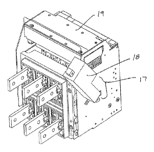
[0038] In Figures 5 through 14 such a device is shown generically
through the use of reference number 17. Device 17 comprises an actuating
means or actuator 18 that is mounted exterior to a circuit breaker cradle
19. The actuating means is movable between an engaged and a
disengaged position such that when it moves from its disengaged to its
engaged position the actuating means causes a circuit breaker 50 to be
racked into cradle 19. Similarly, when actuating means 18 moves from its
12
CA 3024685 2018-11-20
engaged to its disengaged position the actuating means draws out or racks
out breaker 50. In this manner, operation of actuating means 18 causes
circuit breaker 50 to be either racked in or racked out, accordingly. As will
be described in more detail below, in accordance with this aspect of the
invention the actuating means is operable such that it may be moved
between its engaged and disengaged positions without direct or indirect
contact by an operator. Figures 5, 6, 7 and 8 show four of the many
different potential configurations of actuating means that could be utilized
in
accordance with preferred embodiments of the present invention. It will be
appreciated by those of ordinary skill in the art that for illustration
purposes
a particular form of circuit breaker cradle 19 has been shown, however, the
invention is not limited to its application upon such cradles only and the
invention may be applied to any of a wide of variety of circuit breaker
cradles. It should also be appreciated that depending upon the nature of
the cradle in question, the environment within which it is mounted, and also
the nature of actuating means 18, device 17 may also be operatively
secured to an enclosure or frame upon which the cradle is mounted. The
actuating means may be electrically, hydraulically or pneumatically
powered.
[0039] Of
significant importance to device 17 is the fact that actuating
means 18 is controlled remotely such that moving the actuating means
between its engaged and disengaged positions can be accomplished without
the presence of an operator in the vicinity of circuit breaker 50. The
electrical, hydraulic or pneumatic powering of actuating means 18 presents
the ability for device 17 to be controlled in a remote operator or control
station which may be in a secure and safe location either in the same
general vicinity as the breaker or, alternatively, in a completely different
area of a construction site, a centralized location in an oil or gas field or
13
CA 3024685 2018-11-20
plant, or in the case of an underground mine may be potentially be located
at the surface. Control may also be through a wired or wireless network
and could include the option of remotely controlling equipment by means of
a portable computer, smart phone or smart PDA.
[0040]
Regardless of the particular location of the operator, the
important factor is that he or she will be located a safe distance from
circuit
breaker 50 such that when it is racked out or racked in any arcing that may
occur and any subsequent arc flash, while potentially damaging surrounding
equipment, will not inflict harm upon personnel. Through use of device 17,
personnel do not have to approach the equipment to operate it and can
safely stay beyond the arc flash boundary. This presents a significant
advantage over existing cradles and actuating systems that to one extent or
another require an operator to be in either physical contact with the breaker
and cradle, or to be within close proximity. In situations where long
telescopic poles are used to rack in and rack out circuit breakers, such poles
still have a practical limit to their length, after which they become
unmanageable. Even the longest poles that can be handled by an operator
require that operator to be relatively close to the circuit breaker. If the
breaker is situated in an environment that contains explosive gases or dust
particles, any arcing could result in a flash that ignites a sufficient amount
of gas or dust particles to engulf the operator. It is for such reasons that
operators in some instances are required by law, or by practices established
by management, to wear protective suits and head gear when engaged in
such tasks. Completely removing the operator from harm's way in such
circumstances therefore presents a significant advancement over existing
technologies.
14
CA 3024685 2018-11-20
[0041] The remote operation of device 17 also presents the ability to
incorporate a wide variety of different sensors and monitoring mechanisms
either in or around the vicinity of circuit breaker 50. For example, sensors
can be incorporated into the breaker to feed signals to the control station to
indicate whether the breaker is in an open or a closed configuration and
whether the breaker is racked in or racked out. In addition, sensors could
be incorporated in or around the breaker or its cabinet to detect the nature
of the surrounding environment (i.e. the presence of methane or other
explosive gases or dust particles). Thermal sensors could be utilized to
indicate breaker and/or buss temperature to signal an overheating
situation. In some applications it may also be desirable to include lights
and video cameras in which case real-time streaming video could be sent to
an operator's console to visually display the condition of the breaker and its
surrounding components. Where the overheating of the breaker or other
components may be of particular concern an infra-red camera could be
utilized to provide a heat signature of the breaker, the actuating means and
various other related or connected equipment or components.
[0042] Referring again to Figures 6 through 8, in Figure 6 the
embodiment of actuating means 18 that is shown comprises an actuator 20
in the form of an electric gear drive having its shaft operatively connected
to cradle 19 to permit the breaker to be racked in and racked out . Figure 7
shows an alternate embodiment of a similar gear drive actuator, whereas
the embodiment shown in Figure 8 depicts the use of a linear actuator 21
that is connected to a drive box 22 that is turn operatively connected to the
cradle 19.
CA 3024685 2018-11-20
[0043] Figures
9 through 12 show schematically a circuit breaker in a
racked in and a racked out configuration. In these particular figures
actuating means 18 is comprised of a pair of linear actuators, one situated
on each side of the circuit breaker cradle 19. It will be appreciated that
depending upon the particular breaker and cradle in question, and the
configuration of the breaker and cradle, one, two or more actuators may be
necessary in order to rack in and rack out the breaker or, alternatively, may
be desirable in terms of an efficient operation or in terms of built in
redundancy.
[0044] In
accordance with a further aspect of the invention, actuating
means 18 includes a manual override 23 to allow for the manual racking in
and racking out of breaker 50. Depending upon the particular configuration
of the actuating means and its actuator, manual override 23 may take one
of a variety of different forms. In the embodiments shown in the enclosed
drawings, manual override 23 is a drive shaft coupling 24 that is connected
to drive box 22. The drive shaft coupling permits an operator to utilize
either a manual handle or an electrically operated drive mechanism that
may be connected to the drive box to manually to rack the breaker in or
out. Manually
racking the breaker in or out may be necessary or
convenient in particular instances, such as when all power going to the
breaker has been disconnected and there is no chance of an arc flash
occurrence. Manual override 23 also permits the racking out of the breaker
19 in certain emergency situations when for one reason or another
actuating means 18 may not be functional.
[0045] Figures
13 and 14 show exploded views of two forms of
actuating means that may comprise device 17 for racking the breaker in
and out. In Figure 13 there is shown an actuating means 18 that is
16
CA 3024685 2018-11-20
comprised generally of an actuator 20 and a drive box 22. The drive box
contains a shaft 28 that is connected to the breaker mechanism (which
includes the cradle). The drive box may in some cases also include a speed
reducer (could be a worm gear reducer other form of speed reducer) having
a shaft 25 that is connected to a motor 26 by way of a gear box 27. In
Figure 13 the motor is an electric motor, however, it may also be in some
instances a hydraulic motor or a pneumatic power source. It will thus be
appreciated that operation of the motor will result in the rotation of drive
shaft 25, which will in turn result in the rotation of shaft 28 that will
cause
the breaker to be racked in or racked out, depending on the direction of
rotation of motor 26.
[0046] A
mechanically equivalent structure for actuator 20 to that as
shown in Figure 13 is depicted in Figure 14. Here the actuator is comprised
of a linear actuator 21, however, it could equally be an electric solenoid, a
hydraulic or pneumatic cylinder or any other such or similar device. The
linear actuator, at its upper end, is fitted with a bracket 29 that secures
the
actuator to the enclosure or frame to which circuit breaker cradle 19 is
mounted. The opposite end of the actuator is connected to shaft 28 of drive
box 22 through the use of a drive yolk 30. Operation of the actuator will
thus cause shaft 28 to be rotated in either a clockwise or a counter-
clockwise direction to cause the breaker to be either racked in or out. Due
to the nature of the linear actuator, the manual racking in or out of the
breaker will typically require the decoupling of the actuator from the drive
yolk through removal of pin 31. In other embodiments the actuator may be
coupled to the yolk through the use of other releasably securable fastening
means.
17
CA 3024685 2018-11-20
[0047] It will thus be appreciated that through the use of device 17,
the breaker may be racked in and racked out in a manner that helps to
ensure the safety of personnel and that limits their exposure to arc flashes.
The control system to which device 17 is connected (which may include
PLC's and/or other micro processor controls and computers) permits not
only the racking in and out of a breaker, but also provides for the
monitoring of a wide range of system parameters and environmental
factors. The control system may be programmed to automatically rack out
the breaker in certain circumstances where a danger to personnel or
equipment may be present, however, where there is an insufficient
electrical issue to cause the breaker to trip. For example, it may be
desirable to connect fire detection systems and sensors to the control
system for the actuating means that automatically cause the breaker to be
racked out in the event that a fire is detected. Previously, under such
circumstances there would have to be a significant breach of an electrical
system for the breaker to trip or, alternatively, an operator would have to
physically go to the breaker cabinet and manually open the breaker or rack
the breaker out using traditional means.
[0048] From a thorough understanding of the structure and function
of device 17 it will be understood that the device may be utilized on
breakers and breaker cradles that may be employed in any one of a very
wide variety of different applications. For example, while reference has
been made to use of device 17 in association with mining applications it
could equally be used in surface plants, manufacturing facilities, oil and gas
production sites, general commercial applications, construction applications,
etc. The nature of device 17 is such that its usefulness and function is not
limited to use on breakers that control any particular load or piece of
equipment. Further, while in the embodiments of the invention shown in
18
CA 3024685 2018-11-20
the attached drawings device 17 is depicted as being exterior to cradle 19,
it will be appreciated that it could also be constructed so as to be an
internal component situated within or inside the cradle.
[0049] It will also be appreciated that device 17 may be incorporated
into a circuit breaker module 32 that may be received within modular skid
frame 1. The breaker module would typically be connected to a bus bar
within the skid frame to help reduce arc flash probability outside of
situations where the breaker is racked in or racked out. The nature of
module 32 and skid frame 1 is such that modules like those shown
generally in the drawings and noted generally by reference numeral 32 are
essentially plug-and-play modules that can be inserted into defined
compartments within skid frame 1, allowing the skid frame to be configured
as desired for any particular application. That is, in most instances modules
32 will be of one or more defined exterior dimensions so that different
forms of modules (for example different breaker sizes, fused disconnects,
control equipment, relays, etc) can be easily inserted and mounted within
the skid frame. The plug-and-play nature of modules 32 also has a
tendency to help minimize electrical wiring errors at site. The internal
wiring
of the modules can be completed more efficiently and with a greater degree
of accuracy in an assembly plant, after which the fully wired and assembled
modules can be shipped and inserted into a desired compartment within the
skid frame. The various sensors and other monitoring equipment described
above can also in most instances be pre-mounted within module 32. Doing
so further reduces the likelihood of wiring errors on site and allows the
sensors to be connected to a remote operating or control system through
simply connecting a data cable on module 32 into a pre-existing port
situated within the skid frame.
19
CA 3024685 2018-11-20
[0050] Since in most instances the functionality of the breaker cradle
or other equipment housed within module 32 will be remotely controlled,
the module will preferably have a fixed access door or cover having seals
about its peripheral edge to help prevent the ingress of explosive gases,
dust particles, moisture, etc. To ensure that equipment is inoperable while
access doors or covers are open, electrical interlocks may be utilized to
prevent the closing of switches and breakers while doors and/or covers of
module 32 are either open or have been removed. Once again, as in the
case of the other sensing devices described previously, if desired the status
of the covers or doors of module 32 can be displayed remotely at the
operator or control station.
[0051] It is to be understood that what has been described are the
preferred embodiments of the invention and that it may be possible to
make variations to these embodiments while staying within the broad scope
of the invention. Some of these variations have been discussed while
others will be readily apparent to those skilled in the art.
CA 3024685 2018-11-20