Note: Descriptions are shown in the official language in which they were submitted.
CA 03024700 2018-11-16
WO 2018/034662
PCT/US2016/047501
FLOW RATE SIGNALS FOR WIRELESS DOWNHOLE COMMUNICATION
BACKGROUND
Hydrocarbons, such as oil and gas, are commonly obtained from subterranean
formations
.. that may be located onshore or offshore. The development of subterranean
operations and the
processes involved in removing hydrocarbons from a subterranean formation
typically involve a
number of different steps such as, for example, drilling a wellbore at a
desired well site, treating
the wellbore to optimize production of hydrocarbons, and performing the
necessary steps to
produce and process the hydrocarbons from the subterranean formation.
After a wellbore has been formed, various downhole tools may be inserted into
the
wellbore to extract the natural resources such as hydrocarbons or water from
the wellbore, to
inject fluids into the wellbore, and/or to maintain the wellbore. At various
times during
production, injection, and/or maintenance operations, it may be necessary to
regulate fluid flow
into or out of various portions of the wellbore or various portions of the
downhole tools used in
the wellbore.
Some downhole tools are operated in part by onboard electronics that receive
control
signals from operators at the surface. In response to the control signals, the
onboard electronics
can operate the downhole tool in more complicated ways than are typically
possible using hydro-
mechanical control alone. However, because of the distance between the surface
and the
downhole tools, interference created by the formation, generally harsh
downhole conditions, and
various other factors, communication between the surface and the downhole
tools may be
difficult. In some cases, magnetic materials, such as magnetic fracture balls,
are used to signal
electronics within downhole tools. However, such signaling systems limit the
properties of
materials used and complicate the metallurgy of downhole tools. They may also
limit the ability
to pass other tools through the system.
1
CA 03024700 2018-11-16
WO 2018/034662
PCT/US2016/047501
BRIEF DESCRIPTION OF THE DRAWINGS
These drawings illustrate certain aspects of some of the embodiments of the
present
disclosure, and should not be used to limit or define the claims.
Figure 1 is a schematic of a well system following a multiple-zone completion
operation
according to certain embodiments of the present disclosure.
Figure 2 is a block diagram depicting onboard electronics, actuators, and
other electronic
components of a downhole tool according to certain embodiments of the present
disclosure.
Figures 3A-D are a series of graphs representing different flow rate signals
according to
certain embodiments of the present disclosure.
Figures 4A-C are schematic views of a downhole tool according to certain
embodiments
of the present disclosure.
Figure 5 is a process flow diagram for actuating a downhole tool in response
to a flow
rate signal according to certain embodiments of the present disclosure.
While embodiments of this disclosure have been depicted, such embodiments do
not
imply a limitation on the disclosure, and no such limitation should be
inferred. The subject
matter disclosed is capable of considerable modification, alteration, and
equivalents in form and
function, as will occur to those skilled in the pertinent art and having the
benefit of this
disclosure. The depicted and described embodiments of this disclosure are
examples only, and
not exhaustive of the scope of the disclosure.
2
CA 03024700 2018-11-16
WO 2018/034662
PCT/US2016/047501
DESCRIPTION OF CERTAIN EMBODIMENTS
Illustrative embodiments of the present disclosure are described in detail
herein. In the
interest of clarity, not all features of an actual implementation may be
described in this
specification. It will of course be appreciated that in the development of any
such actual
embodiment, numerous implementation-specific decisions may be made to achieve
the specific
implementation goals, which may vary from one implementation to another.
Moreover, it will
be appreciated that such a development effort might be complex and time-
consuming, but would
nevertheless be a routine undertaking for those of ordinary skill in the art
having the benefit of
the present disclosure.
For purposes of this disclosure, an information handling system may include
any
instrumentality or aggregate of instrumentalities operable to compute,
classify, process, transmit,
receive, retrieve, originate, switch, store, display, manifest, detect,
record, reproduce, handle, or
utilize any form of information, intelligence, or data for business,
scientific, control, or other
purposes. For example, an information handling system may be a personal
computer, a network
storage device, or any other suitable device and may vary in size, shape,
performance,
functionality, and price. The information handling system may include random
access
memory (RAM), one or more processing resources such as a central processing
unit (CPU) or
hardware or software control logic, ROM, other types of nonvolatile memory, or
any
combination thereof. Additional components of the information handling system
may include
one or more disk drives, one or more network ports for communication with
external devices as
well as various input and output (I/O) devices, such as a keyboard, a mouse,
and a video display.
The information handling system may also include one or more buses operable to
transmit
communications between the various hardware components. It may also include
one or more
interface units capable of transmitting one or more signals to a controller,
actuator, or like
device.
For the purposes of this disclosure, computer-readable media may include any
instrumentality or aggregation of instrumentalities that may retain data or
instructions or both for
a period of time. Computer-readable media may include, for example, without
limitation, storage
media such as a direct access storage device (for example, a hard disk drive
or floppy disk drive),
a sequential access storage device (for example, a tape disk drive), compact
disk, CD-ROM,
DVD, RAM, ROM, electrically erasable programmable read-only memory (EEPROM),
flash
memory, or any combination thereof; as well as communications media such
wires, optical
fibers, microwaves, radio waves, and other electromagnetic and/or optical
carriers; and/or any
combination of the foregoing.
3
CA 03024700 2018-11-16
WO 2018/034662
PCT/US2016/047501
To facilitate a better understanding of the present disclosure, the following
examples of
certain embodiments are given. In no way should the following examples be read
to limit, or
define, the scope of the invention. Embodiments of the present disclosure may
be applicable to
horizontal, vertical, deviated, or otherwise nonlinear wellbores in any type
of subterranean
formation. Embodiments may be applicable to injection wells as well as
production wells,
including hydrocarbon wells. Embodiments may be implemented using a tool that
is made
suitable for testing, retrieval and sampling along sections of the formation.
Embodiments may be
implemented with tools that, for example, may be conveyed through a flow
passage in tubular
string or using a wireline, slickline, coiled tubing, downhole robot or the
like. "Measurement-
while-drilling" ("MWD") is the term generally used for measuring conditions
downhole
concerning the movement and location of the drilling assembly while the
drilling continues.
"Logging-while-drilling" ("LWD") is the term generally used for similar
techniques that
concentrate more on formation parameter measurement. Devices and methods in
accordance
with certain embodiments may be used in one or more of wireline (including
wireline, slickline,
and coiled tubing), downhole robot, MWD, and LWD operations.
The terms "couple" or "couples" as used herein are intended to mean either an
indirect or
a direct connection. Thus, if a first device couples to a second device, that
connection may be
through a direct connection or through an indirect mechanical or electrical
connection via other
devices and connections. Similarly, the term "communicatively coupled" as used
herein is
intended to mean either a direct or an indirect communication connection. Such
connection may
be a wired or wireless connection such as, for example, Ethernet or LAN. Such
wired and
wireless connections are well known to those of ordinary skill in the art and
will therefore not be
discussed in detail herein. Thus, if a first device communicatively couples to
a second device,
that connection may be through a direct connection, or through an indirect
communication
connection via other devices and connections.
The present disclosure relates to methods and systems for using flow rate
signals for
wireless downhole communication. More specifically, the present disclosure
relates to a method
comprising: generating a first flow rate signal within a wellbore by altering
the flow rate of a
first fluid in the wellbore, wherein the first flow rate signal comprises at
least two detectable
characteristics; detecting the first flow rate signal at a first downhole tool
disposed within the
wellbore; and actuating the first downhole tool in response to detecting the
first flow rate signal.
In certain embodiments, the present disclosure relates to a system comprising:
a well
flow control configured to generate one or more flow rate signals comprising
at least two
detectable characteristics in a wellbore; and a downhole tool disposed in the
wellbore
4
CA 03024700 2018-11-16
WO 2018/034662
PCT/US2016/047501
comprising: one or more actuators; a sensor configured to detect at least one
of the one or more
flow rate signals; and a controller coupled to the sensor and the one or more
actuators and the
controller configured to actuate the downhole tool in response to at least one
of the one or more
flow rate signals.
In certain embodiments, the present disclosure also relates to a system
comprising: a well
flow control configured to generate one or more flow rate signals comprising
at least two
detectable characteristics in a wellbore; and a plurality of downhole tools
disposed in the
wellbore, wherein each of the plurality of downhole tool comprises: one or
more actuators; a
sensor configured to detect at least one of the one or more flow rate signals;
and a controller
coupled to the sensor and the one or more actuators and the controller
configured to actuate the
downhole tool in response to at least one of the one or more flow rate
signals.
Among the many potential advantages to the methods and systems of the present
disclosure, only some of which are alluded to herein, the methods and systems
of the present
disclosure provide wireless communication with downhole tools and avoid
problems caused by
interference created by the foimation, harsh downhole conditions, and various
other factors that
typically make downhole communication difficult. Additionally, unlike magnetic
downhole
signaling, flow rate signaling does not require specific metallurgy of
downhole tools or limit the
ability to pass other tools through the system. In certain embodiments, the
methods and systems
of the present disclosure comprise flow rate signals that comprise at least
two detectable
characteristics. Such flow rate signals may have an advantage over simpler
flow rate signals,
which may not be sufficiently distinct from normal flow rate variations to be
recognized by a
downhole tool, or may not contain sufficient information to perform a desired
downhole
operation.
Embodiments of the present disclosure and its advantages may be understood by
referring to Figures 1 through 5, where like numbers are used to indicate like
and corresponding
parts.
Figure 1 is a schematic of a well system 100 following a multiple-zone
completion
operation. Various types of equipment such as a rotary table, drilling fluid
or production fluid
pumps, drilling fluid tanks (not expressly shown), and other drilling or
production equipment
may be located at well surface or well site 102. A wellbore extends from a
surface and through
subsurface formations. The wellbore has a substantially vertical section 104
and a substantially
horizontal section 106, the vertical section 104 and horizontal section 106
being connected by a
bend 108. The horizontal section 106 extends through a hydrocarbon bearing
formation 124. One
or more casing strings 110 are inserted and cemented into the vertical section
104 to prevent
5
CA 03024700 2018-11-16
WO 2018/034662
PCT/US2016/047501
fluids from entering the wellbore. Fluids may comprise any one or more of
formation fluids
(such as production fluids or hydrocarbons), water, mud, fracturing fluids, or
any other type of
fluid that may be injected into or received from the formation 124.
Although the wellbore shown in Figure 1 includes a horizontal section 106 and
a vertical
section 104, the wellbore may be substantially vertical (for example,
substantially perpendicular
to the surface), substantially horizontal (for example, substantially parallel
to the surface), or
may comprise any other combination of horizontal and vertical sections. While
a land-based
system 100 is illustrated in Figure 1, downhole drilling tools incorporating
teachings of the
present disclosure may be satisfactorily used with drilling equipment located
on offshore
platforms, drill ships, semi-submersibles, and drilling barges (not expressly
shown).
The well system 100 depicted in Figure 1 is generally known as an open hole
well
because the casing strings 110 do not extend through the bend 108 and
horizontal section 106 of
the wellbore. As a result, the bend 108 and horizontal section 106 of the
wellbore are "open" to
the formation. In another embodiment, the well system 100 may be a closed hole
type in which
one or more casing strings 110 are inserted in the bend 108 and the horizontal
section 106 and
cemented in place. In some embodiments, the wellbore may be partially
completed (for example,
partially cased or cemented) and partially uncompleted (for example, uncased
and/or
uncemented).
Well system 100 may include a well flow control 122. Although the well flow
control
122 is shown as associated with a drilling rig at the well site 102, portions
or all of the well flow
control 122 may be located within the wellbore. For example, well flow control
122 may be
located at well site 102, within wellbore at a location different from the
location of a downhole
tool 120, or within a lateral wellbore. In operation, well flow control 122
controls the flow rate
of fluids. In one or more embodiments, well flow control 122 may regulate the
flow rate of a
fluid into or out of the wellbore, into or out of the formation via the
wellbore or both. Fluids may
include hydrocarbons, such as oil and gas, other natural resources, such as
water, a treatment
fluid, or any other fluid within a wellbore.
Well flow control 122 may include, without limitation, valves, sensors,
instrumentation,
tubing, connections, chokes, bypasses, any other suitable components to
control fluid flow into
and out of wellbore, or any combination thereof. An operator or well flow
control 122 or both
may control the rate of fluid flow in the wellbore by, for example,
controlling a choke or the
bypass around a choke at the well site 102. The operator or well flow control
122 or both may
control the rate of fluid flow in the wellbore to generate one or more flow
rate signals. A flow
rate signal may comprise a digital command encoded by any detectable change in
flow rate. In
6
CA 03024700 2018-11-16
WO 2018/034662
PCT/US2016/047501
certain embodiments, the flow rate signals may correspond to a particular
message or
communication to be transmitted to a downhole tool 120.
The embodiment in Figure 1 includes a top production packer 112 disposed in
the
vertical section 104 of the wellbore that seals against an innermost surface
of the casing string
110. Production tubing 114 extends from the production packer 112, along the
bend 108 and
extends along the horizontal section 106 of the wellbore. The production
tubing 114 may also be
used to inject hydrocarbons and other natural resources into the formation 124
via the wellbore.
The production tubing 114 may include multiple sections that are coupled or
joined together by
any suitable mechanism to allow production tubing 114 to extend to a desired
or predetermined
depth in the wellbore. Disposed along the production tubing 114 may be various
downhole tools
including packers 116A-E and sleeves 118A-F. The packers 116A-E engage the
inner surface of
the horizontal section 106, dividing the horizontal section 106 into a series
of production zones
120A-F. In some embodiments, suitable packers 116A-E include, but are not
limited to
compression set packers, swellable packers, inflatable packers, any other
downhole tools,
equipment, or devices for isolating zones, or any combination thereof.
Each of the sleeves 118A-F is generally operable between an open position and
a closed
position such that in the open position, the sleeves 118A-F allow
communication of fluid
between the production tubing 114 and the production zones 120A-F. In one or
more
embodiments, the sleeves 118A-F may be operable to control fluid in one or
more
configurations. For example, the sleeves 118A-F may operate in an intermediate
configuration,
such as partially open, which may cause fluid flow to be restricted, a
partially closed
configuration, which may cause fluid flow to be less restricted than when
partially open, an open
configuration which does not restrict fluid flow or which minimally restricts
fluid flow, a closed
configuration which restricts all fluid flow or substantially all fluid flow,
or any position in
between.
During production, fluid communication is generally from the formation 124,
through the
sleeves 118A-F (for example, in an open configuration), and into the
production tubing 114. The
packers 116A-F and the top production packer 112 seal the wellbore such that
any fluid that
enters the wellbore below the production packer 112 is directed through the
sleeves 118A-F, the
production tubing 114, and the top production packer 112 and into the vertical
section 104 of the
wellbore.
Communication of fluid may also be from the production tubing 114, through the
sleeves
118A-F and into the formation 124, as is the case during hydraulic fracturing.
Hydraulic
fracturing is a method of stimulating production of a well and generally
involves pumping
7
CA 03024700 2018-11-16
WO 2018/034662
PCT/US2016/047501
specialized fracturing fluids down the well and into the formation. As fluid
pressure is increased,
the fracturing fluid creates cracks and fractures in the formation and causes
them to propagate
through the formation. As a result, the fracturing creates additional
communication paths
between the wellbore and the formation. Communication of fluid may also arise
from other
stimulation techniques, such as acid stimulation, water injection, and carbon
dioxide (CO2)
injection.
In wells having multiple zones, such as zones 120A-F of the well system 100
depicted in
Figure 1, it is often necessary to fracture each zone individually. To
fracture only one zone, the
zone is isolated from other zones and fracturing fluid is prevented from
entering the other zones.
In one or more embodiments, isolating a zone being fractured may require
actuating one or more
downhole tools between different configurations, positions, or modes. For
example, isolating any
one or more zones 120A-F may comprise moving any one or more sliding sleeve
tools 118A-F
between a closed configuration and an open configuration, engaging or
disengaging any one or
more packers 116A-E with the wellbore, or changing the configuration of a
valve to redirect the
fracturing fluid.
Fluids may be extracted from or injected into the wellbore and the production
zones
120A-F via the sleeves 118A-F and production tubing 114. For example,
production fluids,
including hydrocarbons, water, sediment, and other materials or substances
found in the
formation 124 may flow from the formation and production zones 120A-F into the
wellbore
through the sidewalls of open hole portions of the wellbore 106 and 108 or
perforations in the
casing string 110. The production fluids may circulate in the wellbore before
being extracted via
downhole tools and the production tubing 114. Additionally, injection fluids,
including
hydrocarbons, water, gasses, foams, acids, and other materials or substances,
may be injected
into the wellbore and the formation via the production tubing 114 and downhole
tools.
Although the well system 100 depicted in Figure 1 comprises sleeves 118A-F and
packers 116A-E, it may comprise any number of additional downhole tools,
including, but not
limited to screens, flow control devices, slotted tubing, additional packers,
additional sleeves,
valves, flapper valves, baffles, sensors, and actuators. The number and types
of downhole tools
may depend on the type of wellbore, the operations being performed in the
wellbore, and
anticipated wellbore conditions. For example, in certain embodiments, downhole
tools may
include a screen to filter sediment from fluids flowing into the wellbore. In
addition, although
the well system 100 depicted in Figure 1 depicts fracturing tools, the methods
and systems of the
present disclosure may be used with any downhole tool capable of detecting a
flow rate signal
for any suitable type of wellbore or downhole operation.
8
CA 03024700 2018-11-16
WO 2018/034662
PCT/US2016/047501
In certain embodiments, a well system 100 may comprise a plurality of downhole
tools
controlled by one or more flow rate signals. For example, a well system 100
may comprise 1, 2,
5, 10, 15, 20, 30, 40, 50, 100, or any other suitable number of downhole
tools. Each downhole
tool may be responsive to a different flow rate signal. In certain
embodiments, a flow rate signal
may be indicative of a command to a plurality of downhole tools
In certain embodiments, a well system 100 may be a multilateral well system.
For
example, in certain embodiments, a downhole tool such as a flapper valve may
actuate in
response to a flow rate signal to open and close zones in a multilateral well
system. In certain
embodiments, a flow rate signal may direct a downhole tool in a multilateral
well system to
guide a fracture ball into one or more zones of the system.
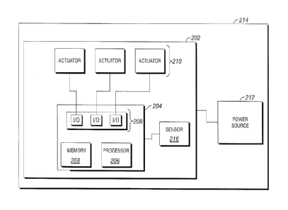
In general, a downhole tool may include onboard electronics and one or more
actuators to
facilitate operation of the downhole tool. Figure 2 is a block diagram
depicting a configuration of
onboard electronics, actuators and other electronic components of a downhole
tool. The onboard
electronics 202 may include a controller 204 for storing and executing
instructions. In general,
the controller 204 includes a processor 206 for executing instructions and a
memory 208 for
storing instructions to be executed by the processor 206 and may further
include one or more
input/output (I/O) modules 209 for communication between the controller 204
and other
electronic components of the downhole tool 214.
The processor 206 may include any hardware, software or both that operates to
control
and process information. The processor 206 may include, without limitation, a
programmable
logic device, a microcontroller, a microprocessor, a digital signal processor,
any suitable
processing device, or any suitable combination of the preceding. The
controller 204 may have
any suitable number, type, or configuration of processors 206. The processor
206 may execute
one or more instructions or sets of instructions to actuate a downhole tool
214, including the
steps described below with respect to Figure 5. The processor 206 may also
execute any other
suitable programs to facilitate adjustable flow control. The controller 204
may further include,
without limitation, switching units, a logic unit, a logic element, a
multiplexer, a demultiplexer, a
switching element, an I/O element, a peripheral controller, a bus, a bus
controller, a register, a
combinatorial logic element, a storage unit, a programmable logic device, a
memory unit, a
neural network, a sensing circuit, a control circuit, a digital to analog
converter (DAC), an analog
to digital converter (ADC), an oscillator, a memory, a filter, an amplifier, a
mixer, a modulator, a
demodulator, a power storage device, and/or any other suitable devices.
In one embodiment, the controller 204 communicates with one or more actuators
210 to
operate the downhole tool 214 between configurations, positions, or modes. In
one embodiment,
9
CA 03024700 2018-11-16
WO 2018/034662
PCT/US2016/047501
the actuators 210 convert electrical energy from a power source 212 to move
one or more
components of the downhole tool 214. For example, in certain embodiments, the
actuators 210
may comprise any suitable actuator, including, but not limited to an
electromagnetic device, such
as a motor, gearbox, or linear screw, a solenoid actuator, a piezoelectric
actuator, a hydraulic
pump, a chemically activated actuator, a heat activated actuator, a pressure
activated actuator, or
any combination thereof. For example, in some embodiments, an actuator may be
a linear
actuator that retracts or extends a pin for permitting or restricting movement
of a downhole tool
component. In certain embodiments, an actuator 210 may rotate a valve body to
redirect a fluid
flow through a downhole tool 214. In some embodiments, for example, a downhole
tool 214
may comprise a rupture disc, and the controller 204 may communicate with a
rupture disc to
cause a failure of the rupture disc. The failure of the rupture disc may
result in a change in
condition (for example, a pressure differential) that may actuate a piston,
pin, or other
component between one or more positions. In one or more embodiments, an
actuator 210 may
comprise a valve biased to rotate, and a brake or clutch to prevent rotation
of the valve. The
controller 204 may communicate with the actuator 210 to operate the brake or
clutch to permit
rotation of the valve.
The onboard electronics 202 and actuators 210 may be connected to a power
source 212.
In one embodiment, the power source 212 may be a battery integrated with the
downhole tool
214 or integrated with another downhole tool electrically connected to the
downhole tool 214.
The power source 212 may also be a downhole generator incorporated into the
downhole tool
214 or as part of other downhole equipment. In another embodiment, the power
source 212 may
be located at the surface.
The downhole tool may include at least one sensor 216 for detecting a physical
property
and converting the property into an electrical signal. The sensor 216 may be
coupled to the
onboard electronics 202, the controller 204, the processor 206, the memory
208, the I/O modules
209, or any combination thereof. The sensor 216 communicates the electrical
signal to the
onboard electronics 202. After receiving the electrical signal, the controller
204 may execute
instructions based, at least in part, on the electrical signal. One or more of
the instructions
executed by the controller 204 may include causing the processor to send one
or more signals to
one or more of the actuators 210, causing the actuators 210 to actuate.
In certain embodiments, the controller 204 may be configured to actuate the
downhole
tool 214 in response to at least one of one or more flow rate signals. For
example, in response to
the one or more flow rate signals received by the sensor 216, controller 204
may transmit an
actuation or command signal to one or more actuators 210 corresponding to one
or more flow
CA 03024700 2018-11-16
WO 2018/034662
PCT/US2016/047501
rate signals received by the sensors 216. In one or more embodiments, a first
flow rate signal
may correspond to or be indicative of a first configuration of a sliding
sleeve tool 118A-F. For
example, when the sensor 216 detects the first flow rate signal, controller
204 may actuate one or
more actuators 210 to move at least one sliding sleeve tool 118 from a closed
configuration or
position to an open configuration or position. As another example, a
subsequent flow rate signal
may correspond to or be indicative of a closed configuration of at least one
sliding sleeve tool
118. When the sensor 216 detects the second flow rate profile, the controller
204 may actuate
one or more actuators 210 to move a corresponding sliding sleeve tool 118 from
an open
configuration to a closed configuration. In one or more embodiments, the
onboard electronics
202 of a downhole tool 214 may be configured to recognize one or more flow
rate signals
indicative of one or more commands. In certain embodiments, a downhole tool
214 may be
configured to recognize one or more flow rate signals prior to introduction
into a wellbore.
Particular flow rate signals may correspond to one or more states of the
onboard electronics 202.
For example, the one or more states may include, but are not limited to, an
indication to
communicate one or more commands to adjust a sliding sleeve tool 118 to one or
more
configurations, a "sleep mode" (such as a low-power mode), a timer state (such
as waiting to
perform or communicate a command until a specified time delay, semaphore,
clock cycle, any
other delay, or any combination thereof), or any other mode or state.
Additionally, flow rate signals may be transmitted from a downhole tool 214 to
another
location, such as well site 102 (shown in Figure 1) or other downhole tools
within the well
system 100 using changes in the flow rate of fluid, which may be detected by a
sensor 216
located at the well site 102 or associated with another downhole tool. For
example, controller
204 may transmit a signal to actuate one or more actuators 210 to increase or
decrease the rate of
fluid flow through the downhole tool 214 to generate one or more flow rate
signals, each of
which may correspond to a particular message or communication to be
transmitted to well site
102 or another downhole tool.
In one or more embodiments, the sensor 216 may be configured to detect at
least one of
one or more flow rate signals. In one or more embodiments, the sensor 216 may
include, but is
not limited to a vibrational sensor, an acoustic sensor, a piezoceramic
sensor, a resistive sensor, a
Coriolis meter, a Doppler flow meter, a pressure sensor, a temperature sensor,
any other sensor
suitable to detect a flow rate signal, and any combination thereof. In one or
more embodiments,
the sensor 216 is not a pressure sensor. In certain embodiments, the sensor
216 may be
positioned on the outer wall of a production tubing 114 and may detect the
flow of a fluid within
the production tubing 114. In one or more embodiments, the sensor 216 does not
contact the
11
CA 03024700 2018-11-16
WO 2018/034662
PCT/US2016/047501
fluid used to generate the flow rate signal. In one or more embodiments, the
fluid used to
generate the flow rate signal may pass through a vortex shedder to increase
the noise and the
detectability of the flow rate.
The sensor 216 converts flow rate signals into electrical signals that reflect
one or more
characteristics of the flow rate signals. As a result, different flow rate
signals may be used to
generate different electrical signals. Because the onboard electronics 202
execute instructions
based on electrical signals from the sensor 216, different flow rate signals
may be used to cause
the controller 204 to execute different instructions and to perform different
functions of the
downhole tool 214. For example, in one embodiment, one flow rate signal may
cause the
controller 204 to execute an instruction issuing a command to an actuator 210
to move in a first
direction, while a subsequent flow rate signal may cause the controller 204 to
issue a command
to the actuator 210 to move in a second direction. In another embodiment, a
flow rate signal may
cause the onboard electronics 202 to enter into a "sleep mode," suspending
operation of a
downhole tool 214 for a period of time in response to detecting the first flow
signal. In certain
embodiments, a flow rate may cause the onboard electronics 202 not to respond
to flow rate
signals for a period of time, or until the sensor 216 receives a specific
signal to "awaken" the
onboard electronics 202.
Flow rate signals may be differentiated by detectable characteristics of the
flow rate
signal. A detectable characteristic may be any characteristic of a flow rate
signal that may be
detected by the sensor 216, captured in the electrical signal generated by the
sensor 216, and
recognized by the onboard electronics 202. In some embodiments, detectable
characteristics may
be generated by altering the flow rate of a fluid in a manner that is
detectable by a sensor 216. In
certain embodiments, for example, types of detectable characteristics may
include, but are not
limited to an increase in flow rate, a decrease in flow rate, a pulse, a
delay, a dwell time, a
duration time, being within a range of flow rates, remaining under a threshold
flow rate,
exceeding a threshold flow rate, dropping below a threshold flow rate,
crossing a threshold flow
rate a certain number of times, a rise time, other suitable detectable
characteristics, and any
combination thereof.
Flow rate signals may be simple or complex. In certain embodiments, a flow
rate signal
may comprise changing a flow rate from no flow to some flow, or any flow in
between. In one or
more embodiments, a flow rate signal may comprise altering the flow rate of a
fluid between one
or more flow rates. In one or more embodiments, a flow rate signal may
comprise altering the
flow rate of a fluid between at least two flow rates. In certain embodiments,
a flow rate signal
may comprise a single detectable characteristic. In certain embodiments, a
flow rate signal may
12
CA 03024700 2018-11-16
WO 2018/034662
PCT/US2016/047501
comprise one or more detectable characteristics, at least two detectable
characteristics, at least
three detectable characteristics, at least four detectable characteristics, or
any other suitable
number of detectable characteristics. In one or more embodiments, flow rate
signals may
comprise one or more of the same detectable characteristic. For example, a
flow rate signal may
comprise at least two pulses, of the same or different magnitude. In some
embodiments, a flow
rate signal may comprise at least two different types of detectable
characteristics. For example, a
flow rate signal comprising at least two detectable characteristics may be
based on a pulse and a
rise time.
In some embodiments, a flow rate signal may comprise another flow rate signal.
For
example, the first flow rate signal may comprise two detectable
characteristics, and the second
flow rate signal may comprise the same two detectable characteristics of the
first flow rate
signal, and an additional detectable characteristic. In some embodiments, a
first downhole tool
214 may actuate one or more actuators 210 in response to a first flow rate
signal, and a second
downhole tool 214 may actuate one or more actuators 210 in response to a
second flow rate
signal, wherein the second flow rate signal comprises the first flow rate
signal. In one or more
embodiments, different actuators 210, the same actuators 210 or any
combination of actuators
210 are actuated by the first downhole tool 214 and the second downhole tool
214.
A flow rate pulse may be a discrete period during which the flow rate is
altered from an
initial flow rate to an altered flow rate, and then returned to the initial
flow rate. An initial flow
rate may be any suitable flow rate, including no flow. An altered flow rate
may be a flow rate
higher or lower than the initial flow rate. A pulse may be based on an
absolute or a relative
change in flow rate.
In some embodiments, the flow rates of a flow rate signal may be selected to
minimize
water waste and to avoid damage to the formation. In some embodiments, the
flow rates of the
flow rate signals may be from about 0 barrels per minute (bbl/min) to about
120 bbl/min, from
about 10 bbl/min to about 50 bbl/min, from about 0 bbl/min to about 5 bbl/
min, from about 1
bbl/min to about 3 bbl/min, or from about from about 10 bbl/min to about 15
bbl/min. In certain
embodiments, the flow rates of the flow rate signal may be based, at least in
part, on whether the
fluid is being produced or injected. For example, in certain embodiments, a
well may produce at
around 3 bbl/min and may be injected at around 1 bbl/min. In one or more
embodiments, for
example, the flow rate of a flow rate signal may vary between 0 bbl/min, 3
bbl/min, 10 bbl/min,
and 20 bbl/min.
13
CA 03024700 2018-11-16
WO 2018/034662
PCT/US2016/047501
Figures 3A-D are graphs depicting flow rate signals over time for different
flow rate
signals. The flow rate signals in Figures 3A-D are merely illustrative and do
not limit the
appropriate types of flow rate signals.
Figure 3A depicts one or more flow rate signals in which the detectable
characteristic is
based on a series of flow rate pulses. For flow rate signals based on flow
rate pulses, the onboard
electronics 202 may be configured to execute instructions in response to
different quantities or
patterns of flow rate pulses. For example, the onboard electronics 202 may
respond to a total
quantity of pulses, a specific number of pulses within a period of time, a
delay between pulses, a
specific pattern of pulses and delays, or any similar signal. Several possible
flow rate signals
may be represented by the pulses depicted in Figure 3A. For example, flow rate
signals based on
flow rates pulses may include a total of five pulses, three quick pulses in
quick succession, or a
delay, followed by three quick pulses. Although Figure 3A depicts a binary
flow rate signal of
low and high values, the flow rate signal could be non-binary.
Figure 3B is a graph illustrating flow rate signals in which the detectable
characteristic is
based on a flow rate exceeding a threshold flow rate. For flow rate signals
based on a threshold
flow rate, the onboard electronics 202 may be configured to execute
instructions in response to a
flow rate being above a threshold flow rate, being within a range of flow
rates, remaining under a
threshold flow rate, or crossing a threshold flow rate a certain number of
times.
Figure 3C is a graph illustrating flow rate signals in which the detectable
characteristic is
based on the duration or dwell time of one or more flow rates. For flow rate
signals based on
dwell time, the onboard electronics 202 may be configured to execute
instructions in response to
a fluid flowing at, above, or below a particular flow rate for a particular
period of time, or in
response to no flow for a particular period of time or both.
Figure 3D is a graph illustrating flow rate signals in which the detectable
characteristic is
based on increases and decreases in flow rate. In certain embodiments, the
detectable
characteristic may be the amount of flow rate change as well as the duration
over which the flow
rate remains changed. Accurate measurement of the flow rate may be required in
order to detect
the amount of flow rate change. In some embodiments, the detectable
characteristic may be
whether the flow rate increased or decreased more than a threshold amount.
Such a detectable
characteristic may be independent of the absolute magnitude of the increase or
decrease, so long
as the increase or decrease in flow rate is above a threshold amount.
For downhole tools 214 configured to respond to two or more flow rate signals,
the two
or more flow rate signals may or may not be of the same type of signal. For
example, in one
embodiment, one flow rate signal may be based on a threshold flow rate, while
another flow rate
14
CA 03024700 2018-11-16
WO 2018/034662
PCT/US2016/047501
signal may be based on a series of flow rate pulses. In another embodiment, a
flow rate signal
may be based on a first threshold flow rate, while another flow rate signal
may be based on a
different threshold flow rate.
In certain embodiments, a first downhole tool disposed within a wellbore may
be
responsive to a first flow rate signal formed in a first fluid and a second
downhole tool disposed
within the wellbore may be responsive to a second flow rate signal formed in a
second fluid. For
example, in one embodiment, a first flow rate signal may be generated within a
wellbore
penetrating at least a portion of a subterranean formation 124 by altering the
flow rate of a first
fluid and the first flow rate signal may be detected at a first downhole tool
in the wellbore. In
some embodiments, a second flow rate signal may be generated within the
wellbore by alerting
the flow rate of a second fluid and the second flow rate signal may be
detected at a second
downhole tool in the wellbore. The first fluid and the second fluid may be the
same or different
fluids.
Flow rate signals may be based on absolute flow rates or relative flow rates
or both. In
certain embodiments, a relative flow rate signal may comprise a percentage
increase or decrease
with respect to a steady state flow rate. Relative flow rates signals may
comprise pulses,
thresholds, dwell time components based on a steady state flow or any
combination thereof For
example, in some embodiments, a relative flow rate signal may comprise one or
more pulses of a
10% increase over a steady state flow rate.
The onboard electronics 202 may also take into account an order in which the
flow rate
signals or detectable characteristics or both are received by the onboard
electronics 202. For
example, the onboard electronics 202 may respond to a flow rate signal based
on flow rate pulses
but only after first detecting another flow rate signal based on a threshold
flow rate.
Figure 4A depicts a portion of a horizontal wellbore having production tubing
114 on
which a series of downhole tools 604A-D and 606A-C are disposed. The downhole
tools 604A-
D and 606A-C may include four packers 604A-D and three sliding sleeve tools
606A-C or any
other suitable configuration of packers 604 and sleeve tools 606.
Figures 4B and 4C are each detailed views of sliding sleeve tool 606A. Figure
4B depicts
the sliding sleeve tool 606A in a closed configuration while Figure 4C depicts
the sliding sleeve
tool 606A in an open configuration. Because the sliding sleeve tools 606A-C
are substantially
the same, the description of the structure and operation of sliding sleeve
tool 606A, below,
generally applies to the other sliding sleeve tools 606B-C.
As depicted in Figure 4B, sliding sleeve tool 606A includes an actuator 614
and onboard
electronics 608, which further include a sensor 609. The sensor 609 may be
configured to detect
CA 03024700 2018-11-16
WO 2018/034662
PCT/US2016/047501
one or more flow rate signals. The sliding sleeve tool 606A further includes a
collapsible baffle
615. The baffle 615 is configured to collapse when fluid is introduced into a
chamber 616 behind
the baffle 615.
The sliding sleeve tool 606A includes a series of communication ports 620
around its
circumference. The communication ports 620 allow fluid to flow between the
production tubing
114 and the formation 124 when the sliding sleeve tool 606A is in the open
configuration as
depicted in Figure 4C. In certain embodiments, the sliding sleeve tool 606A
may comprise a
sleeve 622, which may move from the closed configuration to the open
configuration in response
to one or more flow rate signals.
By configuring the sliding sleeve tools 606A-C as described, the sliding
sleeve tools
606A-C may be sequentially opened. This permits sequential completion of
production zones
120A-F adjacent to each sliding sleeve tool 606A-C. To move the sleeve 622
from the closed
configuration to the open configuration, a ball 624 is dropped, injected or
launched into the
wellbore or a flow rate signal signals the sleeve 622. If the baffles 615 are
in the open
configuration, a ball 624 may pass through the sliding sleeve tool 606A and
further down the
wellbore. However, if the baffle 615 is collapsed, a ball 624 may be caught by
and seal against
the baffle 615.
As fluid is pumped into the wellbore, the ball 624 prevents the fluid from
flowing
through the sliding sleeve tool 606A. This causes hydraulic pressure to build
behind the ball 624,
exerting a force on the ball 624 and baffle 615. As the pressure continues to
build, the force
eventually becomes sufficient to slide the sleeve 622 to its open
configuration, exposing the ports
620.
In some embodiments, flow rate signals may command baffles 615 within one or
more
sliding sleeve tools 606A-C to deploy. Deployment of the baffles 615 may cause
a ball 624 to
land on a particular baffle 615, to have a custom configuration of clusters
above the dropped ball
624, or both. In some embodiments, one or more flow rate signals may be used
to signal various
sliding sleeve tools 606A-C to open and close, eliminating the need to use a
ball 624. In certain
embodiments, one or more flow rate signals may be used to signal a higher
sliding sleeve tool
606 to open and a lower sliding sleeve tool 606 to close. In some embodiments,
a flow rate
signal may command a sliding sleeve tool 606 to open and a flapper valve to
close. One or more
flow rate signals may direct a combination of baffles 615 and sliding sleeve
tools 606 to deploy
in certain configurations.
In certain embodiments, a completion operation may require only one flow rate
signal per
sliding sleeve tool 606. In some embodiments, sliding sleeve tools 606 may be
required to
16
CA 03024700 2018-11-16
WO 2018/034662
PCT/US2016/047501
perform additional functions and additional flow rate signals may be required.
If an operation is
carried out that requires flow rates changes that are similar to a flow rate
signal recognized by a
sliding sleeve tool 606, such an operation may cause the onboard electronics
608 of a sliding
sleeve tool 606 to detect false signals and actuate out of sequence.
To prevent out of sequence actuation, the sliding sleeve tools 606 may be
configured to
respond to a toggle flow rate signal that toggles the sliding sleeve tool 606
into and out of a
"sleep" mode. During sleep mode, all functions of the sliding sleeve tool 606,
including actuating
in response to flow rate signals, are suspended until the toggle flow rate
signal is used to "wake"
the sliding sleeve tool. An alternative to sleep mode is for the sliding
sleeve tools to respond to a
reset flow rate signal by resetting themselves. In certain embodiments, the
resetting could be a
resetting of the logic within the onboard electronics 608. Specifically, a
flow rate signal may be
used to reset the detection of flow rate signals for one or more of the
sliding sleeve tools 606.
Figure 5 is a flowchart of a method according to certain embodiments of the
present
disclosure. The steps of method 500 may be performed by various computer
programs or non-
transitory computer readable media that may include instructions operable to
perform, when
executed, one or more of the steps described below. The programs and computer
readable media
may be configured to direct a processor or other suitable unit to retrieve and
execute the
instructions from the computer readable media.
At step 501, a first flow rate signal is generated within a wellbore
penetrating at least a
portion of a subterranean formation 124. For example, as discussed with
reference to Figure 1, a
well flow control 122, an operator, or both may alter the flow rate of fluid
in the wellbore. The
well flow control 122, operator, or both may be configured to generate one or
more flow rate
signals. The first flow rate signal may comprise at least two detectable
characteristics, as
discussed above. In certain embodiments, the first flow rate signal may be
based on flow rate
pulses, on the flow rate exceeding a threshold flow rate, on duration or dwell
time at a flow rate,
or any combination thereof, as discussed above with respect to Figures 3A-C.
At step 502, a first flow rate signal may be detected at a first downhole tool
214 disposed
within the wellbore. The first downhole tool 214 may be located remotely from
the well flow
control 122, operator, or both that altered the flow rate of the fluid. As
discussed above with
respect to Figure 1, the first downhole tool 214 may include a sensor capable
of receiving or
detecting a change in a parameter related to fluid flowing in the wellbore.
At step 503, the first downhole tool is actuated in response to detecting the
first flow rate
signal. For example, as discussed with reference to Figure 2, a sensor 216 may
transmit a signal
to controller 204 indicating the detection of the first flow rate signal. The
controller 204 may
17
CA 03024700 2018-11-16
WO 2018/034662
PCT/US2016/047501
actuate one or more actuators 210 of the first downhole tool in response to
the first flow rate
signal. For example, in certain embodiments, the first downhole tool may be a
sliding sleeve tool
606 and the actuating may change the sliding sleeve tool 606 from a closed
configuration to an
open configuration, or from an open configuration to a closed configuration,
in response to the
detection of the first flow rate signal. In some embodiments, the method 500
may further
comprise steps 504-506.
At step 504, a second flow rate signal may be generated within the wellbore by
altering
the flow rate of the fluid in the wellbore. As discussed above with respect to
step 501, the well
flow control 122, operator, or both may control the flow rate of the fluid to
generate the flow rate
signal. The second flow rate signal may comprise a single detectable
characteristic, at least two
detectable characteristics, at least three detectable characteristics, or any
suitable number of
detectable characteristics.
At step 505, a second flow rate signal may be detected at a second downhole
tool
disposed within the wellbore, similar to step 502. The second downhole tool
may be located
remotely from the well flow control 122, or operator or both that altered the
flow rate of the
fluid. As discussed above with respect to Figure 2, the second downhole tool
may include a
sensor 216 capable of receiving or detecting a change in a parameter related
to fluid flowing in
the wellbore.
At step 506, the second downhole tool is actuated in response to detecting the
first flow
rate signal. For example, as discussed with reference to Figure 2, a sensor
216 may transmit a
signal to controller 204 indicating the detection of the second flow rate
signal. The controller 204
may actuate one or more actuators 210 of the second downhole tool in response
to the second
flow rate signal. The second downhole tool may be the same or a different type
of tool from the
first downhole tool. In certain embodiments, for example, the first downhole
tool may be a
sliding sleeve tool 606 and the second downhole tool may be a valve, and the
first or second flow
rate signals or both may operate to actuate the sliding sleeve tool 606 and
valve to carry out a
wellbore operation, such as fracturing.
Modifications, additions, or omissions may be made to method 500 without
departing
from the scope of the present disclosure. For example, the order of the steps
may be performed in
a different manner than that described and some steps may be performed at the
same time.
Additionally, each individual step may include additional steps without
departing from the scope
of the present disclosure.
An embodiment of the present disclosure is a method comprising: generating a
first flow
rate signal within a wellbore by altering the flow rate of a first fluid in
the wellbore, wherein the
18
CA 03024700 2018-11-16
WO 2018/034662
PCT/US2016/047501
first flow rate signal comprises at least two detectable characteristics;
detecting the first flow
rate signal at a first downhole tool disposed within the wellbore; and
actuating the first downhole
tool in response to detecting the first flow rate signal.
In one or more embodiments described in the preceding paragraph, the method
further
comprises: generating a second flow rate signal within the wellbore by
altering the flow rate of a
second fluid in the wellbore; detecting the second flow rate signal at a
second downhole tool
disposed within the wellbore; and actuating the second downhole tool in
response to detecting
the second flow rate signal. In certain embodiments, the first downhole tool
is a sliding sleeve
tool and the second downhole tool is a valve or a baffle. In some embodiments,
the first
downhole tool and the second downhole tool are sliding sleeve tools.
In one or more embodiments described in the preceding paragraph, the second
flow rate
signal is the same as the first flow rate signal.
In one or more embodiments described in the preceding two paragraphs, the
first fluid is
the same as the second fluid.
In one or more embodiments described in the preceding four paragraphs, each of
the at
least two detectable characteristics comprises one or more of an increase in
flow rate, a decrease
in flow rate, a pulse, a delay, a dwell time, a duration time, being within a
range of flow rates,
remaining under a threshold flow rate, exceeding a threshold flow rate,
dropping below a
threshold flow rate, crossing a threshold flow rate a certain number of times,
and a rise time.
In one or more embodiments described in the preceding five paragraphs, the
first
downhole tool is a sliding sleeve tool.
In one or more embodiments described in the preceding paragraph, the actuating
comprises changing the sliding sleeve tool from a closed configuration to an
open configuration.
In one or more embodiments described in the preceding two paragraphs, the
method
further comprises detecting the first flow rate signal at a valve disposed
within the wellbore and
actuating the valve in response to detecting the first flow rate signal at the
valve.
In one or more embodiments described in the preceding eight paragraphs, the
first
downhole tool comprises one or more of a vibrational sensor, an acoustic
sensor, a piezoceramic
sensor, a resistive sensor, a Coriolis meter and a Doppler flow meter.
In one or more embodiments described in the preceding nine paragraphs, the
method
further comprises suspending operation of the first downhole tool for a period
of time in
response to detecting the first flow rate signal.
Another embodiment of the present disclosure is a system comprising: a well
flow
control configured to generate one or more flow rate signals comprising at
least two detectable
19
CA 03024700 2018-11-16
WO 2018/034662
PCT/US2016/047501
characteristics in a wellbore; and a downhole tool disposed in the wellbore
comprising: one or
more actuators; a sensor configured to detect at least one of the one or more
flow rate signals;
and a controller coupled to the sensor and the one or more actuators and
configured to actuate the
downhole tool in response to at least one of the one or more flow rate
signals.
In one or more embodiments described in the preceding paragraph, the system
further
comprises a production string disposed within the wellbore to which the
downhole tool is
coupled.
In one or more embodiments described in the preceding two paragraphs, the
downhole
tool is selected from the group consisting of a sliding sleeve tool, a packer,
and a valve.
In one or more embodiments described in the preceding three paragraphs, each
of the at
least two detectable characteristics comprises one or more of an increase in
flow rate, a decrease
in flow rate, a pulse, a delay, a dwell time, a duration time, being within a
range of flow rates,
remaining under a threshold flow rate, exceeding a threshold flow rate,
dropping below a
threshold flow rate, crossing a threshold flow rate a certain number of times,
and a rise time.
Another embodiment of the present disclosure is a system comprising: a well
flow
control configured to generate one or more flow rate signals comprising at
least two detectable
characteristics in a wellbore; and a plurality of downhole tools disposed in
the wellbore, wherein
each of the plurality of downhole tool comprises: one or more actuators; a
sensor configured to
detect at least one of the one or more flow rate signals; and a controller
coupled to the sensor
and the one or more actuators and the controller configured to actuate the
downhole tool in
response to at least one of the one or more flow rate signals.
In one or more embodiments described in the preceding paragraph, the system
further
comprises a production string disposed within the wellbore to which the
plurality of downhole
tools are coupled.
In one or more embodiments described in the preceding two paragraphs, each of
the
plurality of downhole tools are selected from the group consisting of: a
sliding sleeve tool, a
packer, and a valve.
In one or more embodiments described in the preceding three paragraphs, each
of the at
least two detectable characteristics comprises one or more of an increase in
flow rate, a decrease
in flow rate, a pulse, a delay, a dwell time, a duration time, being within a
range of flow rates,
remaining under a threshold flow rate, exceeding a threshold flow rate,
dropping below a
threshold flow rate, crossing a threshold flow rate a certain number of times,
and a rise time.
Therefore, the present disclosure is well adapted to attain the ends and
advantages
mentioned as well as those that are inherent therein. The particular
embodiments disclosed
CA 03024700 2018-11-16
WO 2018/034662
PCT/US2016/047501
above are illustrative only, as the present disclosure may be modified and
practiced in different
but equivalent manners apparent to those skilled in the art having the benefit
of the teachings
herein. While numerous changes may be made by those skilled in the art, such
changes are
encompassed within the spirit of the subject matter defined by the appended
claims.
Furthermore, no limitations are intended to the details of construction or
design herein shown,
other than as described in the claims below. It is therefore evident that the
particular illustrative
embodiments disclosed above may be altered or modified and all such variations
are considered
within the scope and spirit of the present disclosure. In particular, every
range of values (e.g.,
"from about a to about b," or, equivalently, "from approximately a to b," or,
equivalently, "from
approximately a-b") disclosed herein is to be understood as referring to the
power set (the set of
all subsets) of the respective range of values. The terms in the claims have
their plain, ordinary
meaning unless otherwise explicitly and clearly defined by the patentee.
21