Language selection

Search

Patent 3024927 Summary

Third-party information liability

Some of the information on this Web page has been provided by external sources. The Government of Canada is not responsible for the accuracy, reliability or currency of the information supplied by external sources. Users wishing to rely upon this information should consult directly with the source of the information. Content provided by external sources is not subject to official languages, privacy and accessibility requirements.

Claims and Abstract availability

Any discrepancies in the text and image of the Claims and Abstract are due to differing posting times. Text of the Claims and Abstract are posted:

  • At the time the application is open to public inspection;
  • At the time of issue of the patent (grant).
(12) Patent: (11) CA 3024927
(54) English Title: IMPROVED FLUID COUPLING
(54) French Title: COUPLEUR HYDRAULIQUE AMELIORE
Status: Granted and Issued
Bibliographic Data
(51) International Patent Classification (IPC):
  • F16J 15/16 (2006.01)
  • F16J 15/56 (2006.01)
  • F16L 21/05 (2006.01)
(72) Inventors :
  • READMAN, MATT (United Kingdom)
(73) Owners :
  • SELF-ENERGISING COUPLING COMPANY LIMITED
(71) Applicants :
  • SELF-ENERGISING COUPLING COMPANY LIMITED (United Kingdom)
(74) Agent: PARLEE MCLAWS LLP
(74) Associate agent:
(45) Issued: 2020-12-29
(86) PCT Filing Date: 2016-11-24
(87) Open to Public Inspection: 2017-06-01
Examination requested: 2018-11-20
Availability of licence: N/A
Dedicated to the Public: N/A
(25) Language of filing: English

Patent Cooperation Treaty (PCT): Yes
(86) PCT Filing Number: PCT/GB2016/053690
(87) International Publication Number: WO 2017089807
(85) National Entry: 2018-11-20

(30) Application Priority Data:
Application No. Country/Territory Date
1520763.2 (United Kingdom) 2015-11-24

Abstracts

English Abstract


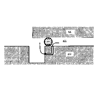
A vent is provided between a sealing surface and a gap. An aperture to the
vent on the
sealing surface is relatively small so that fluid pressure does not act to
deform the seal
as it crosses said aperture. Said aperture is spaced off-set from the gap on
the sealing
surface. The off-set provides a portion of sealing surface adjacent the gap
and
between the gap and aperture against which the seal can contact. The vent acts
to
allow fluid to enter the gap before the seal starts to cross the gap and to
therefore act
to equalise pressure on either side of the seal. Consequently, as the seal
transitions
across the gap and the sealing between two parts is lost, the fluid pressure
imbalance
that would otherwise act to deform the seal into the gap has been reduced. The
risk of
seal damage during the transition has been reduced.


French Abstract

L'invention concerne un coupleur hydraulique qui possède une première partie (100), scellée sur une surface de scellement d'une seconde partie (200), la première partie portant une partie de scellement (300) et la seconde partie comprenant un espace (G) dans la surface de scellement, sur lequel l'élément de scellement est agencé pour une transition. Une évacuation (210) est située entre la surface de scellement et l'espace. Une ouverture vers l'évacuation, sur la surface de scellement, est relativement petite, de telle sorte que la pression de fluide n'agit pas de façon à déformer le scellement quand il croise ladite ouverture. Ladite ouverture est espacée, de façon décalée, de l'espace sur la surface de scellement. Le décalage fournit une partie de surface de scellement adjacente à l'espace et entre l'espace et l'ouverture contre laquelle le joint peut venir en contact. L'évacuation agit de façon à permettre au fluide (400) d'entrer dans l'espace avant que le joint ne commence à croiser l'espace, et, par conséquent, d'agir de façon à égaliser la pression de chaque côté du joint. Par conséquent, à mesure que le joint effectue une transition à travers l'espace et que l'étanchéité entre deux parties est perdue, le déséquilibre de pression de fluide qui, sinon, agirait pour déformer le joint dans l'espace, a été réduit. Le risque de détérioration du joint pendant la transition a donc également été réduit.

Claims

Note: Claims are shown in the official language in which they were submitted.


4
CLAIMS
1. A fluid coupling having a first part sealed to a sealing surface of a
second part, wherein;
the first part carries a sealing part;
the second part includes a gap in the sealing surface, across which the
sealing part is
arranged to transition;
wherein the second part includes a vent between the sealing surface and the
gap, the
vent forming a fluid passageway between an opening on the sealing surface and
an opening to
the gap, the opening on the sealing surface being offset from the gap and
arranged to allow fluid
to enter the gap before the sealing part reaches the gap and the seal between
the sealing
surface and first part is broken.
2. The fluid coupling of claim 1, wherein the second part is formed from a
first section and
a second, separate section, the gap being formed by a junction between the
first and second
sections.
3. The fluid coupling of claim 2, wherein the first section includes a
first vent for venting
said seal as it moves in one direction, and the second section includes a
second vent for
venting said seal as it moves in a second direction.
4. The fluid coupling of claim 1 or 2, wherein the vent comprises a bent
fluid passageway
between the opening on the sealing surface and the opening to the gap.
5. The fluid coupling of claim 3, wherein each of the first vent and the
second vent
comprise a bent fluid passageway between the opening on the sealing surface
and the opening
to the gap.

Description

Note: Descriptions are shown in the official language in which they were submitted.


I
IMPROVED FLUID COUPLING
FIELD
[01] The present invention relates to an improved fluid coupling and in
particular to a
fluid coupling having a moving seal which transitions across a gap.
BACKGROUND
[02] Fluid couplings are known wherein a seal transitions across a gap
during the
coupling or decoupling process. The seal is attached to one part that slides
relative to
another. The seal provides a sealing point between the two parts and closes a
separation distance between the two parts. The gap is an area having a
localised
increase in the separation distance. In use, fluid is retained on one side of
the seal.
Fluid pressure exerts a force on the seal. When the seal transitions across
relatively
small gaps, the fluid pressure is not sufficient to deform the seal into the
gap.
However, when the gap is relatively large, the fluid pressure can urge the
seal to
deform into the gap, wherein further movement of the seal risks damaging seal
as it
becomes sheared between the sliding parts.
[03] Whilst in some case gaps can be engineered to be maintained
sufficiently small
enough for the seal to transition across without damage, relatively large gaps
cannot
always be avoided, particularly in instances where the gap is created between
two
joined parts where the gap between the two parts cannot be easily controlled.
A
particular example is described in PCT/GB2008/050039. As shown in Figures la,
1 b,
here, an annular seal 10 has to transition across a gap 20 created at a join
between
two parts 30a, 30b. Because the gap 20 between the two joined parts cannot be
easily
controlled, the gap is often sufficiently large so that as the seal 10
transitions across,
fluid 40 retained on the one side of the seal exerts a sufficiently high force
against the
pressure on the other side of the seal to deform the seal into the gap. As the
seal
completes the transition across the gap it therefore becomes damaged. In a de-
coupling operation, the damage to the seal can prevent re-coupling to the same
performance levels. For instance, the recoupled seal may fail at a lower fluid
pressure
than an undamaged seal.
SUMMARY
[04] It is an object of the present invention to attempt to overcome at
least one of the
above or other disadvantages. It is an aim of the present invention to provide
an
improved coupling wherein the risk of damaging a seal transitioning across a
relatively
large gap is reduced.
CA 3024927 2020-03-04

2
[05] In the exemplary embodiments a vent is provided between a sealing
surface
and a gap. An aperture to the vent on the sealing surface is relatively small
so that
fluid pressure does not act to deform the seal as it cross said aperture. Said
aperture
is spaced off-set from the gap on the sealing surface. The off-set provides a
portion of
sealing surface adjacent the gap and between the gap and aperture against
which the
seal can contact. The vent acts to allow fluid to enter the gap before the
seal starts to
cross the gap and to therefore act to equalise pressure on either side of the
seal.
Consequently, as the seal transitions across the gap and the sealing between
two parts
is lost, the fluid pressure imbalance that would otherwise act to deform the
seal into the
gap has been reduced. The risk of seal damage during the transition has also
therefore been reduced.
BRIEF DESCRIPTION OF DRAWINGS
[06] For a better understanding of the invention, and to show how
embodiments of
the same may be carried into effect, reference will now be made, by way of
example, to
the accompanying diagrammatic drawings in which:
[07] Figures la and lb show a prior art example of a seal transitioning
across a gap;
[08] Figures 2a, 2b and 2c show cross-sectional partial views of a fluid
coupling
according to an exemplary embodiment showing a seal transitioning across a
gap.
DESCRIPTION OF EMBODIMENTS
[09] Referring to Figures 2a, 2b and 2c, a part of a fluid coupling is
shown. It will be
appreciated by those skilled in the art that the fluid coupling may be any
type of fluid
coupling wherein a part slides relative to another part and a seal closing a
separation
(S) between the two sliding parts has to transition across a gap (G). For
instance, the
seal may be an annular seal such as an o-ring seal wherein the seal is carried
on the
first part and the gap on the second part. Here, one of the parts may be a
probe or
piston and the other a socket. A description of the wider coupling is not
necessary and
is therefore omitted here.
[10] In Figures 2a, 2b and 2c, the two parts that slide relative to each
other are
labelled a first part 100 and a second part 200. The first part 100 carries
the seal 300.
In a first arrangement (Figure 2A), the seal 300 seals the separation between
the two
parts. As will be widely understood, fluid 400 on one side of the seal is
prevented from
escaping to the other side by the seal. The fluid pressure can be high and
cause a
pressure imbalance between the two sides of the seal.
CA 3024927 2020-03-04

3
[11] The second part includes a gap. The gap is an area having a localised
increase in the separation distance between the two parts. For instance the
gap may
be a channel or groove in the second part, or the second part may be an
assembly of
two separate components that are joined together. The second part also
includes a
vent 210. The vent is a passageway that extends between an aperture open to
the gap
and an aperture on a sealing face of the second part spaced from the gap. The
aperture on the sealing face is spaced approximately the same distance as a
thickness
of the seal. That is, the spacing is such that there is sufficient sealing
surface between
the edge of the gap and the aperture for the seal to locate. The aperture on
the sealing
surface can be machined or formed into the coupling in a precise and
controlled
manner and is arranged to be sufficiently small that the fluid pressure does
not force
the seal to deform into the aperture.
[12] In the exemplary embodiments, the vent is shown as an aperture having
an
elbow. Suitably formed by drilling two blind bores to meet. However, other
fluid
passageway design are envisaged, that create the vent between the two
surfaces.
[13] During operation of the coupling, the seal 300 is caused to transition
from one
side of the gap to the other. Once a sealing point of the seal moves past the
aperture
to the vent on the sealing surface, fluid is able to enter the vent. At this
point in the
transition, the seal has not started to cross the gap to allow the fluid to
enter the gap
between the seal and sealing surface. However, fluid can now enter the gap
through
the vent. Consequently, the fluid pressure on either side of the seal is
equalised, or at
least partially equalised. As such, when the seal reaches the gap, the fluid
pressure
acting on the seal and which would otherwise force the seal to deform into the
gap is
reduced due to the equalising or part equalising of the pressures on either
side of the
seal. The seal can therefore transition across the gap with no or
substantially reduced
deformation into the gap. Therefore the risk of causing damage to the seal
during the
transition is reduced or removed.
[14] Although a few preferred embodiments have been shown and described, it
will
be appreciated by those skilled in the art that various changes and
modifications might
be made without departing from the scope of the invention, as defined in the
appended
claims.
CA 3024927 2020-03-04

Representative Drawing
A single figure which represents the drawing illustrating the invention.
Administrative Status

2024-08-01:As part of the Next Generation Patents (NGP) transition, the Canadian Patents Database (CPD) now contains a more detailed Event History, which replicates the Event Log of our new back-office solution.

Please note that "Inactive:" events refers to events no longer in use in our new back-office solution.

For a clearer understanding of the status of the application/patent presented on this page, the site Disclaimer , as well as the definitions for Patent , Event History , Maintenance Fee  and Payment History  should be consulted.

Event History

Description Date
Grant by Issuance 2020-12-29
Inactive: Cover page published 2020-12-28
Common Representative Appointed 2020-11-07
Inactive: Final fee received 2020-10-19
Pre-grant 2020-10-19
Change of Address or Method of Correspondence Request Received 2020-07-23
Letter Sent 2020-07-23
Inactive: Protest/prior art received 2020-07-23
Notice of Allowance is Issued 2020-07-16
Letter Sent 2020-07-16
Notice of Allowance is Issued 2020-07-16
Inactive: Approved for allowance (AFA) 2020-06-02
Inactive: Q2 passed 2020-06-02
Amendment Received - Voluntary Amendment 2020-03-04
Examiner's Report 2020-02-13
Inactive: Report - No QC 2020-02-11
Amendment Received - Voluntary Amendment 2019-12-13
Common Representative Appointed 2019-10-30
Inactive: S.30(2) Rules - Examiner requisition 2019-10-15
Inactive: Report - QC failed - Minor 2019-10-08
Amendment Received - Voluntary Amendment 2019-05-23
Amendment Received - Voluntary Amendment 2019-03-19
Inactive: Acknowledgment of national entry - RFE 2018-11-30
Inactive: Cover page published 2018-11-28
Inactive: First IPC assigned 2018-11-26
Letter Sent 2018-11-26
Inactive: IPC assigned 2018-11-26
Application Received - PCT 2018-11-26
National Entry Requirements Determined Compliant 2018-11-20
Request for Examination Requirements Determined Compliant 2018-11-20
All Requirements for Examination Determined Compliant 2018-11-20
Application Published (Open to Public Inspection) 2017-06-01

Abandonment History

There is no abandonment history.

Maintenance Fee

The last payment was received on 2020-11-23

Note : If the full payment has not been received on or before the date indicated, a further fee may be required which may be one of the following

  • the reinstatement fee;
  • the late payment fee; or
  • additional fee to reverse deemed expiry.

Please refer to the CIPO Patent Fees web page to see all current fee amounts.

Fee History

Fee Type Anniversary Year Due Date Paid Date
Basic national fee - standard 2018-11-20
Reinstatement (national entry) 2018-11-20
Request for examination - standard 2018-11-20
MF (application, 2nd anniv.) - standard 02 2018-11-26 2018-11-20
MF (application, 3rd anniv.) - standard 03 2019-11-25 2019-11-04
Final fee - standard 2020-11-16 2020-10-19
MF (application, 4th anniv.) - standard 04 2020-11-24 2020-11-23
MF (patent, 5th anniv.) - standard 2021-11-24 2021-11-15
MF (patent, 6th anniv.) - standard 2022-11-24 2022-11-14
MF (patent, 7th anniv.) - standard 2023-11-24 2023-11-14
Owners on Record

Note: Records showing the ownership history in alphabetical order.

Current Owners on Record
SELF-ENERGISING COUPLING COMPANY LIMITED
Past Owners on Record
MATT READMAN
Past Owners that do not appear in the "Owners on Record" listing will appear in other documentation within the application.
Documents

To view selected files, please enter reCAPTCHA code :


To view images, click a link in the Document Description column. To download the documents, select one or more checkboxes in the first column and then click the "Download Selected in PDF format (Zip Archive)" or the "Download Selected as Single PDF" button.

List of published and non-published patent-specific documents on the CPD .

If you have any difficulty accessing content, you can call the Client Service Centre at 1-866-997-1936 or send them an e-mail at CIPO Client Service Centre.


Document
Description 
Date
(yyyy-mm-dd) 
Number of pages   Size of Image (KB) 
Representative drawing 2020-12-01 1 26
Claims 2018-11-20 1 24
Drawings 2018-11-20 2 251
Abstract 2018-11-20 1 65
Description 2018-11-20 3 143
Cover Page 2018-11-28 1 38
Claims 2018-11-21 1 27
Claims 2019-12-13 1 27
Description 2019-12-13 3 150
Abstract 2019-12-13 1 18
Drawings 2019-12-13 2 166
Description 2020-03-04 3 157
Cover Page 2020-12-01 1 59
Acknowledgement of Request for Examination 2018-11-26 1 175
Notice of National Entry 2018-11-30 1 233
Commissioner's Notice - Application Found Allowable 2020-07-16 1 551
Patent cooperation treaty (PCT) 2018-11-20 9 264
National entry request 2018-11-20 5 167
International Preliminary Report on Patentability 2018-11-20 6 174
International search report 2018-11-20 2 48
Voluntary amendment 2018-11-20 2 62
Amendment / response to report 2019-03-19 2 44
Amendment / response to report 2019-05-23 1 35
Examiner Requisition 2019-10-15 4 235
Maintenance fee payment 2019-11-04 1 26
Amendment / response to report 2019-12-13 14 634
Examiner requisition 2020-02-13 3 134
Amendment / response to report 2020-03-04 9 287
Change to the Method of Correspondence 2020-07-23 4 100
Protest-Prior art 2020-07-23 4 100
Acknowledgement of Receipt of Prior Art 2020-08-31 1 171
Final fee 2020-10-19 3 92