Sélection de la langue

Search

Sommaire du brevet 3024927 

Énoncé de désistement de responsabilité concernant l'information provenant de tiers

Une partie des informations de ce site Web a été fournie par des sources externes. Le gouvernement du Canada n'assume aucune responsabilité concernant la précision, l'actualité ou la fiabilité des informations fournies par les sources externes. Les utilisateurs qui désirent employer cette information devraient consulter directement la source des informations. Le contenu fourni par les sources externes n'est pas assujetti aux exigences sur les langues officielles, la protection des renseignements personnels et l'accessibilité.

Disponibilité de l'Abrégé et des Revendications

L'apparition de différences dans le texte et l'image des Revendications et de l'Abrégé dépend du moment auquel le document est publié. Les textes des Revendications et de l'Abrégé sont affichés :

  • lorsque la demande peut être examinée par le public;
  • lorsque le brevet est émis (délivrance).
(12) Brevet: (11) CA 3024927
(54) Titre français: COUPLEUR HYDRAULIQUE AMELIORE
(54) Titre anglais: IMPROVED FLUID COUPLING
Statut: Accordé et délivré
Données bibliographiques
(51) Classification internationale des brevets (CIB):
  • F16J 15/16 (2006.01)
  • F16J 15/56 (2006.01)
  • F16L 21/05 (2006.01)
(72) Inventeurs :
  • READMAN, MATT (Royaume-Uni)
(73) Titulaires :
  • SELF-ENERGISING COUPLING COMPANY LIMITED
(71) Demandeurs :
  • SELF-ENERGISING COUPLING COMPANY LIMITED (Royaume-Uni)
(74) Agent: PARLEE MCLAWS LLP
(74) Co-agent:
(45) Délivré: 2020-12-29
(86) Date de dépôt PCT: 2016-11-24
(87) Mise à la disponibilité du public: 2017-06-01
Requête d'examen: 2018-11-20
Licence disponible: S.O.
Cédé au domaine public: S.O.
(25) Langue des documents déposés: Anglais

Traité de coopération en matière de brevets (PCT): Oui
(86) Numéro de la demande PCT: PCT/GB2016/053690
(87) Numéro de publication internationale PCT: WO 2017089807
(85) Entrée nationale: 2018-11-20

(30) Données de priorité de la demande:
Numéro de la demande Pays / territoire Date
1520763.2 (Royaume-Uni) 2015-11-24

Abrégés

Abrégé français

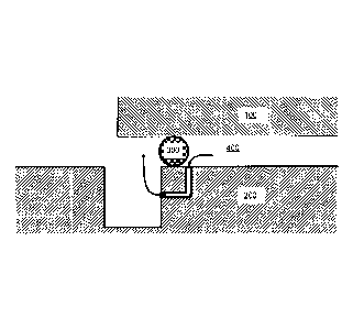
L'invention concerne un coupleur hydraulique qui possède une première partie (100), scellée sur une surface de scellement d'une seconde partie (200), la première partie portant une partie de scellement (300) et la seconde partie comprenant un espace (G) dans la surface de scellement, sur lequel l'élément de scellement est agencé pour une transition. Une évacuation (210) est située entre la surface de scellement et l'espace. Une ouverture vers l'évacuation, sur la surface de scellement, est relativement petite, de telle sorte que la pression de fluide n'agit pas de façon à déformer le scellement quand il croise ladite ouverture. Ladite ouverture est espacée, de façon décalée, de l'espace sur la surface de scellement. Le décalage fournit une partie de surface de scellement adjacente à l'espace et entre l'espace et l'ouverture contre laquelle le joint peut venir en contact. L'évacuation agit de façon à permettre au fluide (400) d'entrer dans l'espace avant que le joint ne commence à croiser l'espace, et, par conséquent, d'agir de façon à égaliser la pression de chaque côté du joint. Par conséquent, à mesure que le joint effectue une transition à travers l'espace et que l'étanchéité entre deux parties est perdue, le déséquilibre de pression de fluide qui, sinon, agirait pour déformer le joint dans l'espace, a été réduit. Le risque de détérioration du joint pendant la transition a donc également été réduit.


Abrégé anglais


A vent is provided between a sealing surface and a gap. An aperture to the
vent on the
sealing surface is relatively small so that fluid pressure does not act to
deform the seal
as it crosses said aperture. Said aperture is spaced off-set from the gap on
the sealing
surface. The off-set provides a portion of sealing surface adjacent the gap
and
between the gap and aperture against which the seal can contact. The vent acts
to
allow fluid to enter the gap before the seal starts to cross the gap and to
therefore act
to equalise pressure on either side of the seal. Consequently, as the seal
transitions
across the gap and the sealing between two parts is lost, the fluid pressure
imbalance
that would otherwise act to deform the seal into the gap has been reduced. The
risk of
seal damage during the transition has been reduced.

Revendications

Note : Les revendications sont présentées dans la langue officielle dans laquelle elles ont été soumises.


4
CLAIMS
1. A fluid coupling having a first part sealed to a sealing surface of a
second part, wherein;
the first part carries a sealing part;
the second part includes a gap in the sealing surface, across which the
sealing part is
arranged to transition;
wherein the second part includes a vent between the sealing surface and the
gap, the
vent forming a fluid passageway between an opening on the sealing surface and
an opening to
the gap, the opening on the sealing surface being offset from the gap and
arranged to allow fluid
to enter the gap before the sealing part reaches the gap and the seal between
the sealing
surface and first part is broken.
2. The fluid coupling of claim 1, wherein the second part is formed from a
first section and
a second, separate section, the gap being formed by a junction between the
first and second
sections.
3. The fluid coupling of claim 2, wherein the first section includes a
first vent for venting
said seal as it moves in one direction, and the second section includes a
second vent for
venting said seal as it moves in a second direction.
4. The fluid coupling of claim 1 or 2, wherein the vent comprises a bent
fluid passageway
between the opening on the sealing surface and the opening to the gap.
5. The fluid coupling of claim 3, wherein each of the first vent and the
second vent
comprise a bent fluid passageway between the opening on the sealing surface
and the opening
to the gap.

Description

Note : Les descriptions sont présentées dans la langue officielle dans laquelle elles ont été soumises.


I
IMPROVED FLUID COUPLING
FIELD
[01] The present invention relates to an improved fluid coupling and in
particular to a
fluid coupling having a moving seal which transitions across a gap.
BACKGROUND
[02] Fluid couplings are known wherein a seal transitions across a gap
during the
coupling or decoupling process. The seal is attached to one part that slides
relative to
another. The seal provides a sealing point between the two parts and closes a
separation distance between the two parts. The gap is an area having a
localised
increase in the separation distance. In use, fluid is retained on one side of
the seal.
Fluid pressure exerts a force on the seal. When the seal transitions across
relatively
small gaps, the fluid pressure is not sufficient to deform the seal into the
gap.
However, when the gap is relatively large, the fluid pressure can urge the
seal to
deform into the gap, wherein further movement of the seal risks damaging seal
as it
becomes sheared between the sliding parts.
[03] Whilst in some case gaps can be engineered to be maintained
sufficiently small
enough for the seal to transition across without damage, relatively large gaps
cannot
always be avoided, particularly in instances where the gap is created between
two
joined parts where the gap between the two parts cannot be easily controlled.
A
particular example is described in PCT/GB2008/050039. As shown in Figures la,
1 b,
here, an annular seal 10 has to transition across a gap 20 created at a join
between
two parts 30a, 30b. Because the gap 20 between the two joined parts cannot be
easily
controlled, the gap is often sufficiently large so that as the seal 10
transitions across,
fluid 40 retained on the one side of the seal exerts a sufficiently high force
against the
pressure on the other side of the seal to deform the seal into the gap. As the
seal
completes the transition across the gap it therefore becomes damaged. In a de-
coupling operation, the damage to the seal can prevent re-coupling to the same
performance levels. For instance, the recoupled seal may fail at a lower fluid
pressure
than an undamaged seal.
SUMMARY
[04] It is an object of the present invention to attempt to overcome at
least one of the
above or other disadvantages. It is an aim of the present invention to provide
an
improved coupling wherein the risk of damaging a seal transitioning across a
relatively
large gap is reduced.
CA 3024927 2020-03-04

2
[05] In the exemplary embodiments a vent is provided between a sealing
surface
and a gap. An aperture to the vent on the sealing surface is relatively small
so that
fluid pressure does not act to deform the seal as it cross said aperture. Said
aperture
is spaced off-set from the gap on the sealing surface. The off-set provides a
portion of
sealing surface adjacent the gap and between the gap and aperture against
which the
seal can contact. The vent acts to allow fluid to enter the gap before the
seal starts to
cross the gap and to therefore act to equalise pressure on either side of the
seal.
Consequently, as the seal transitions across the gap and the sealing between
two parts
is lost, the fluid pressure imbalance that would otherwise act to deform the
seal into the
gap has been reduced. The risk of seal damage during the transition has also
therefore been reduced.
BRIEF DESCRIPTION OF DRAWINGS
[06] For a better understanding of the invention, and to show how
embodiments of
the same may be carried into effect, reference will now be made, by way of
example, to
the accompanying diagrammatic drawings in which:
[07] Figures la and lb show a prior art example of a seal transitioning
across a gap;
[08] Figures 2a, 2b and 2c show cross-sectional partial views of a fluid
coupling
according to an exemplary embodiment showing a seal transitioning across a
gap.
DESCRIPTION OF EMBODIMENTS
[09] Referring to Figures 2a, 2b and 2c, a part of a fluid coupling is
shown. It will be
appreciated by those skilled in the art that the fluid coupling may be any
type of fluid
coupling wherein a part slides relative to another part and a seal closing a
separation
(S) between the two sliding parts has to transition across a gap (G). For
instance, the
seal may be an annular seal such as an o-ring seal wherein the seal is carried
on the
first part and the gap on the second part. Here, one of the parts may be a
probe or
piston and the other a socket. A description of the wider coupling is not
necessary and
is therefore omitted here.
[10] In Figures 2a, 2b and 2c, the two parts that slide relative to each
other are
labelled a first part 100 and a second part 200. The first part 100 carries
the seal 300.
In a first arrangement (Figure 2A), the seal 300 seals the separation between
the two
parts. As will be widely understood, fluid 400 on one side of the seal is
prevented from
escaping to the other side by the seal. The fluid pressure can be high and
cause a
pressure imbalance between the two sides of the seal.
CA 3024927 2020-03-04

3
[11] The second part includes a gap. The gap is an area having a localised
increase in the separation distance between the two parts. For instance the
gap may
be a channel or groove in the second part, or the second part may be an
assembly of
two separate components that are joined together. The second part also
includes a
vent 210. The vent is a passageway that extends between an aperture open to
the gap
and an aperture on a sealing face of the second part spaced from the gap. The
aperture on the sealing face is spaced approximately the same distance as a
thickness
of the seal. That is, the spacing is such that there is sufficient sealing
surface between
the edge of the gap and the aperture for the seal to locate. The aperture on
the sealing
surface can be machined or formed into the coupling in a precise and
controlled
manner and is arranged to be sufficiently small that the fluid pressure does
not force
the seal to deform into the aperture.
[12] In the exemplary embodiments, the vent is shown as an aperture having
an
elbow. Suitably formed by drilling two blind bores to meet. However, other
fluid
passageway design are envisaged, that create the vent between the two
surfaces.
[13] During operation of the coupling, the seal 300 is caused to transition
from one
side of the gap to the other. Once a sealing point of the seal moves past the
aperture
to the vent on the sealing surface, fluid is able to enter the vent. At this
point in the
transition, the seal has not started to cross the gap to allow the fluid to
enter the gap
between the seal and sealing surface. However, fluid can now enter the gap
through
the vent. Consequently, the fluid pressure on either side of the seal is
equalised, or at
least partially equalised. As such, when the seal reaches the gap, the fluid
pressure
acting on the seal and which would otherwise force the seal to deform into the
gap is
reduced due to the equalising or part equalising of the pressures on either
side of the
seal. The seal can therefore transition across the gap with no or
substantially reduced
deformation into the gap. Therefore the risk of causing damage to the seal
during the
transition is reduced or removed.
[14] Although a few preferred embodiments have been shown and described, it
will
be appreciated by those skilled in the art that various changes and
modifications might
be made without departing from the scope of the invention, as defined in the
appended
claims.
CA 3024927 2020-03-04

Dessin représentatif
Une figure unique qui représente un dessin illustrant l'invention.
États administratifs

2024-08-01 : Dans le cadre de la transition vers les Brevets de nouvelle génération (BNG), la base de données sur les brevets canadiens (BDBC) contient désormais un Historique d'événement plus détaillé, qui reproduit le Journal des événements de notre nouvelle solution interne.

Veuillez noter que les événements débutant par « Inactive : » se réfèrent à des événements qui ne sont plus utilisés dans notre nouvelle solution interne.

Pour une meilleure compréhension de l'état de la demande ou brevet qui figure sur cette page, la rubrique Mise en garde , et les descriptions de Brevet , Historique d'événement , Taxes périodiques et Historique des paiements devraient être consultées.

Historique d'événement

Description Date
Accordé par délivrance 2020-12-29
Inactive : Page couverture publiée 2020-12-28
Représentant commun nommé 2020-11-07
Inactive : Taxe finale reçue 2020-10-19
Préoctroi 2020-10-19
Requête pour le changement d'adresse ou de mode de correspondance reçue 2020-07-23
Lettre envoyée 2020-07-23
Inactive : Opposition/doss. d'antériorité reçu 2020-07-23
Un avis d'acceptation est envoyé 2020-07-16
Lettre envoyée 2020-07-16
Un avis d'acceptation est envoyé 2020-07-16
Inactive : Approuvée aux fins d'acceptation (AFA) 2020-06-02
Inactive : Q2 réussi 2020-06-02
Modification reçue - modification volontaire 2020-03-04
Rapport d'examen 2020-02-13
Inactive : Rapport - Aucun CQ 2020-02-11
Modification reçue - modification volontaire 2019-12-13
Représentant commun nommé 2019-10-30
Inactive : Dem. de l'examinateur par.30(2) Règles 2019-10-15
Inactive : Rapport - CQ échoué - Mineur 2019-10-08
Modification reçue - modification volontaire 2019-05-23
Modification reçue - modification volontaire 2019-03-19
Inactive : Acc. récept. de l'entrée phase nat. - RE 2018-11-30
Inactive : Page couverture publiée 2018-11-28
Inactive : CIB en 1re position 2018-11-26
Lettre envoyée 2018-11-26
Inactive : CIB attribuée 2018-11-26
Demande reçue - PCT 2018-11-26
Exigences pour l'entrée dans la phase nationale - jugée conforme 2018-11-20
Exigences pour une requête d'examen - jugée conforme 2018-11-20
Toutes les exigences pour l'examen - jugée conforme 2018-11-20
Demande publiée (accessible au public) 2017-06-01

Historique d'abandonnement

Il n'y a pas d'historique d'abandonnement

Taxes périodiques

Le dernier paiement a été reçu le 2020-11-23

Avis : Si le paiement en totalité n'a pas été reçu au plus tard à la date indiquée, une taxe supplémentaire peut être imposée, soit une des taxes suivantes :

  • taxe de rétablissement ;
  • taxe pour paiement en souffrance ; ou
  • taxe additionnelle pour le renversement d'une péremption réputée.

Veuillez vous référer à la page web des taxes sur les brevets de l'OPIC pour voir tous les montants actuels des taxes.

Historique des taxes

Type de taxes Anniversaire Échéance Date payée
Taxe nationale de base - générale 2018-11-20
Rétablissement (phase nationale) 2018-11-20
Requête d'examen - générale 2018-11-20
TM (demande, 2e anniv.) - générale 02 2018-11-26 2018-11-20
TM (demande, 3e anniv.) - générale 03 2019-11-25 2019-11-04
Taxe finale - générale 2020-11-16 2020-10-19
TM (demande, 4e anniv.) - générale 04 2020-11-24 2020-11-23
TM (brevet, 5e anniv.) - générale 2021-11-24 2021-11-15
TM (brevet, 6e anniv.) - générale 2022-11-24 2022-11-14
TM (brevet, 7e anniv.) - générale 2023-11-24 2023-11-14
Titulaires au dossier

Les titulaires actuels et antérieures au dossier sont affichés en ordre alphabétique.

Titulaires actuels au dossier
SELF-ENERGISING COUPLING COMPANY LIMITED
Titulaires antérieures au dossier
MATT READMAN
Les propriétaires antérieurs qui ne figurent pas dans la liste des « Propriétaires au dossier » apparaîtront dans d'autres documents au dossier.
Documents

Pour visionner les fichiers sélectionnés, entrer le code reCAPTCHA :


Pour visualiser une image, cliquer sur un lien dans la colonne description du document. Pour télécharger l'image (les images), cliquer l'une ou plusieurs cases à cocher dans la première colonne et ensuite cliquer sur le bouton "Télécharger sélection en format PDF (archive Zip)" ou le bouton "Télécharger sélection (en un fichier PDF fusionné)".

Liste des documents de brevet publiés et non publiés sur la BDBC .

Si vous avez des difficultés à accéder au contenu, veuillez communiquer avec le Centre de services à la clientèle au 1-866-997-1936, ou envoyer un courriel au Centre de service à la clientèle de l'OPIC.


Description du
Document 
Date
(aaaa-mm-jj) 
Nombre de pages   Taille de l'image (Ko) 
Dessin représentatif 2020-12-01 1 26
Revendications 2018-11-20 1 24
Dessins 2018-11-20 2 251
Abrégé 2018-11-20 1 65
Description 2018-11-20 3 143
Page couverture 2018-11-28 1 38
Revendications 2018-11-21 1 27
Revendications 2019-12-13 1 27
Description 2019-12-13 3 150
Abrégé 2019-12-13 1 18
Dessins 2019-12-13 2 166
Description 2020-03-04 3 157
Page couverture 2020-12-01 1 59
Accusé de réception de la requête d'examen 2018-11-26 1 175
Avis d'entree dans la phase nationale 2018-11-30 1 233
Avis du commissaire - Demande jugée acceptable 2020-07-16 1 551
Traité de coopération en matière de brevets (PCT) 2018-11-20 9 264
Demande d'entrée en phase nationale 2018-11-20 5 167
Rapport prélim. intl. sur la brevetabilité 2018-11-20 6 174
Rapport de recherche internationale 2018-11-20 2 48
Modification volontaire 2018-11-20 2 62
Modification / réponse à un rapport 2019-03-19 2 44
Modification / réponse à un rapport 2019-05-23 1 35
Demande de l'examinateur 2019-10-15 4 235
Paiement de taxe périodique 2019-11-04 1 26
Modification / réponse à un rapport 2019-12-13 14 634
Demande de l'examinateur 2020-02-13 3 134
Modification / réponse à un rapport 2020-03-04 9 287
Changement à la méthode de correspondance 2020-07-23 4 100
Protestation-Antériorité 2020-07-23 4 100
Accusé de réception d'antériorité 2020-08-31 1 171
Taxe finale 2020-10-19 3 92