Note: Descriptions are shown in the official language in which they were submitted.
CWCAS-523
HYDRAULIC UNDERBALANCE INITIATED SAFETY FIRING HEAD,
WELL COMPLETION APPARATUS INCORPORATING SAME,
AND METHOD OF USE
FIELD
100021 This disclosure generally relates to a firing head assembly. More
specifically,
a firing head assembly having a safety assembly, for use in conjunction with a
perforating
gun is described.
BACKGROUND
100031 In the extraction of hydrocarbons, such as fossil fuels (e.g.,
oil) and natural gas,
from underground wellbores extending deeply below the surface, complex
machinery and
explosive devices are utilized. It is common practice to facilitate the flow
of production
fluid by perforating a fluid bearing subterranean formation using a
perforating gun, which
is lowered into the wellbore to the depth of the formation and then detonated
to form
perforations in the formation surrounding the perforating gun. A firing head
assembly is
coupled to the gun and initiated / activated to fire the gun. While the firing
head assembly
may be coupled to the perforating gun before the gun is lowered into the
wellbore, it is
often preferred for safety and other reasons, to allow initiation of the
firing head only after
the gun is positioned in the wellbore. An initiator is designed to fire the
explosive train in
the perforating gun after the initiator sees / receives an appropriate command
from the
surface.
1
CA 3024982 2020-02-25
CWCAS-523
[0004] It is very important that the firing head used to initiate
explosives in a
perforating gun be reliable and safe in operation. There have been numerous
accidents
resulting in severe injury or death where an explosive well tool, such as a
perforating gun,
fires prematurely at the surface of a wellbore while personnel are rigging the
tool in
preparation for running it into the wellbore.
[0005] There may be countless reasons for an operator or personnel to
decide not to
fire a perforating gun that has been run into the wellbore. Such reasons may
include
problems with running the perforating gun into the wellbore (i.e., running in
hole),
problems with other completion equipment or problems with the perforating gun
assembly
or its related components. In addition, one potential risk is that after the
firing procedure
is performed, there may be no positive indication that the perforating gun
actually fired,
which may mean that there are live explosives/shaped charges returning to the
surface of
the wellbore. This may endanger all personnel and equipment present at the
surface when
the perforating guns are retrieved to the surface.
[0006] In view of continually increasing safety requirements and the
problems
described hereinabove, there is a need for a firing head assembly that
facilitates safe
initiation of shaped charges in a perforating gun. There is also a need for a
firing head
assembly for use in a perforating gun that reduces the risk of property damage
and bodily
harm, including death, in a firing condition. Furthermore, there is a need for
a firing head
assembly having a safety feature, which will not allow the perforating gun to
fire unless an
operator selects the option to fire the perforating gun. Additionally, there
is a need for a
firing head assembly that allows an operator to abort a firing operation in a
manner that
prevents firing of the perforating gun.
BRIEF DESCRIPTION
[00071 According to an aspect, the present embodiments may be associated
with a
firing head assembly. The firing head assembly includes a tubular housing
having a first
end, a second end, and a lumen that extends between the first and second ends.
An upper
piston is slidably disposed proximate to the first end of the tubular housing,
and a lower
2
CA 3024982 2018-11-22
CWCAS-523
piston is slidably disposed proximate to the second end of the tubular
housing. Each piston
at least partially extends into the lumen of the tubular housing. The firing
assembly may
further include a compressible member within the tubular housing. The
compressible
member has a first end portion that is coupled to the upper piston, and a
second end portion
that is coupled to the lower piston. The firing head assembly includes a
safety assembly
having a sleeve and a key. In an embodiment, the sleeve includes a
substantially zigzag-
shaped slot having a plurality of stop points. The key may radially extend
from an external
surface of the upper piston through the zigzag-shaped slot in such a manner
that slides
through the slot and engages with at least one of the plurality of stop points
of the slot. The
firing head assembly may further include a first securing element positioned
along the
second end of the tubular housing. The upper piston operatively adjusts the
arrangement
of the key within the zigzag-shaped slot to activate the firing head assembly.
[0008] According to an aspect, the present embodiments may also be
associated with
a well completion apparatus. The well completion apparatus includes a
perforating gun,
and a firing head assembly operably associated with the perforating gun.
Similar to the
firing head assembly described hereinabove, the well completion apparatus
includes a
tubular housing, upper and lower pistons positioned proximate to the first and
second ends
of the tubular housing, respectively, and slidably moveable within a lumen of
the tubular
housing. A compressible member is positioned within the lumen, and is
adjustable
between a relaxed state, a compressed state and a partially compressed state.
The
compressible member has a first end portion that abuts the upper piston, and a
second end
portion that abuts the lower piston. The pressure activated firing assembly
further includes
a safety assembly, which may be configured as described hereinabove.
[0009] Further embodiments of the disclosure are associated with a method
of using a
pressure activated firing head assembly in both a firing condition and a non-
firing
condition. In an embodiment, the method includes positioning a perforating gun
at a
desired location. The perforating gun includes a firing head assembly
configured
substantially as described hereinabove. The firing head assembly includes a
tubular
housing having a first end, a second end, an inner diameter, and a lumen
extending between
3
CA 3024982 2018-11-22
CWCAS-523
the first and second ends of the tubular housing. In an embodiment, the firing
head
assembly includes an upper piston and a lower piston. The upper piston and the
tubular
housing at least partially define an upper chamber of the lumen above the
upper piston,
while the lower piston and the tubular housing at least partially define a
lower chamber of
the lumen below the lower piston. The compressible member is in an
intermediate chamber
between the upper and lower chambers. The upper, intermediate, and lower
chambers each
have a respective pressure. According to an aspect, the method further
includes adjusting
the first pressure and the second pressure to initiate an event. The event may
be one of
triggering an explosive reaction in the firing condition, and canceling an
explosive reaction
in the non-firing condition.
BRIEF DESCRIPTION OF THE FIGURES
[0010] A more particular description will be rendered by reference to
specific
embodiments thereof that are illustrated in the appended drawings.
Understanding that
these drawings depict only typical embodiments thereof and are not therefore
to be
considered to be limiting of its scope, exemplary embodiments will be
described and
explained with additional specificity and detail through the use of the
accompanying
drawings in which:
[0011] FIG. 1 is a partial cross-sectional, perspective view of a firing
head assembly,
illustrating a compressible member in a relaxed state and a safety assembly,
according to
an embodiment;
[0012] FIG. 2 is a partial cross-sectional, perspective view of the firing
head assembly
of FIG. 1, illustrating the compressible member in a charged state;
[0013] FIG. 3A is a partial cross-sectional, perspective view of the firing
head
assembly of FIG. 1, illustrating the compressible member in a partially
compressed state
and securing elements in place;
4
CA 3024982 2018-11-22
CWCAS -523
[0014] FIG. 3B is a partial cross-sectional, perspective view of the firing
head assembly
of FIG. 3A, illustrating the securing elements in a broken configuration,
according to an
embodiment;
[0015] FIG. 4 is a partial cross-sectional, perspective view of the firing
head assembly
of FIG. 1, illustrating the compressible member in another fully compressed
state;
[0016] FIG. 5 is a partial cross-sectional, perspective view of the firing
head assembly
of FIG. 1, illustrating the compressible member in another relaxed state;
[0017] FIG. 6 is a partial cross-sectional, perspective view of a firing
head assembly,
illustrating a compressible gas, according to an aspect;
[0018] FIG. 7 is a perspective view of the safety assembly of FIGS. 1 to 6;
[0019] FIG. 8A is a perspective view of a shear ring for use as a securing
element with
a firing head assembly, according to an embodiment;
[0020] FIG. 8B is a perspective view of a shear pin for use as a securing
element with
a firing head assembly, according to an embodiment
[0021] FIG. 9 is a cross-sectional view of a well completion apparatus
including a
pressure activated firing head assembly, according to an embodiment;
[0022] FIG. 10A is a chart illustrating a method of using a firing head
assembly in a
firing condition, according to an aspect; and
[0023] FIG. 10B is a chart illustrating a method of using a firing head
assembly in a
non-firing condition, according to an aspect.
[0024] Various features, aspects, and advantages of the embodiments will
become
more apparent from the following detailed description, along with the
accompanying
figures in which like numerals represent like components throughout the
figures and text.
CA 3024982 2018-11-22
CWCAS -523
The various described features are not necessarily drawn to scale, but are
drawn to
emphasize specific features relevant to some embodiments.
[0025] The headings used herein are for organizational purposes only and
are not meant
to limit the scope of the description or the claims. To facilitate
understanding, reference
numerals have been used, where possible, to designate like elements common to
the
figures.
DETAILED DESCRIPTION
[0026] Reference will now be made in detail to various embodiments. Each
example
is provided by way of explanation, and is not meant as a limitation and does
not constitute
a definition of all possible embodiments.
[0027] As used herein, the term "underbalanced" refers to a procedure where
before
perforating a wellbore, the pressure in the wellbore is lower than the static
pressure inside
the adjacent formation. Once the wellbore has been perforated, fluid (e.g.,
oil and gas) in
the formation flows into the wellbore.
[0028] For purposes of illustrating features of the embodiments, reference
will be made
to various figures. FIGS. 1-6 generally illustrate various embodiments of a
firing head
assembly. As will be discussed in connection with the individual illustrated
embodiments,
the firing head assembly generally includes a tubular housing/body, an upper
piston and a
lower piston, and a compressible member arranged between the upper and lower
pistons.
The firing head assembly may also include a safety assembly having a sleeve
and a key.
The safety assembly in combination with the compressible member helps to
facilitate safe
rigging up and installation of a perforating gun string into the wellbore,
safe initiation of
shaped charges in a perforating gun, and safe retrieval of the perforating gun
from a
wellbore.
[0029] Turning now to the figures, FIGS. 1-6 illustrate a perspective view
of a firing
head assembly 10 (with at least some components being partially cutaway). The
firing
6
CA 3024982 2018-11-22
CWCAS-523
head assembly 10 includes a tubular housing or tubular body 20, an upper
piston 32, a
lower piston 34, and a compressible member 40 arranged within the tubular
housing 20.
[0030] According to an aspect, the tubular housing 20 includes a first end
22 and a
second end 24. The second end 24 may be spaced apart from the first end 22 by
the housing
body, with a lumen (i.e., interior space) 26 extending therebetween. The lumen
26 has an
inner diameter ID, which in some embodiments, is constant along a length L of
the tubular
housing 20.
[0031] The upper and lower pistons or driving members 32, 34 are
illustrated as being
spaced apart from each other. According to an aspect, the upper piston 32 is
slidably
disposed proximate to the first end 22 of the tubular housing 20, while the
lower piston 34
is slidably disposed proximate to the second end 24 of the tubular housing 20.
Each of the
upper and lower pistons 32, 34 at least partially extends into the lumen 26 of
the tubular
housing 20, and may be longitudinally movable therein. According to an aspect,
the upper
piston 32 move towards and/or away from the lower piston 34. As will be
discussed further
below, movement of the upper piston 32 within the lumen 26 operatively adjusts
the
arrangement of a key 54 of a safety assembly 50 within the zigzag-shaped slot
53 in order
to activate the firing head assembly 10. The lower piston 34 is configured to
move away
from the upper piston 32 when the firing head assembly is activated, as will
be described
in further detail hereinbelow. According to an aspect, at least one of the
upper piston 32
and the lower piston 34 is compressively fitted and partially arranged within
the lumen 26
of the tubular body 20. In this configuration, movement of the pistons 32, 34
is facilitated
by the application or removal of a force, i.e. a change in the wellbore
pressure, onto the
pistons 32, 34, thereby causing them to slide within the lumen 26.
[0032] A compressible member 40 is illustrated in FIGS. 1-6 as being
disposed within
the lumen 26 of the tubular housing 20 between the upper piston 32 and the
lower piston
34. The compressible member 40 may be sized to fit within the lumen 26 of the
tubular
housing 20. According to an aspect, the compressible member 40 is resilient
and
moveable/adjustable within the lumen 26. The compressible member 40 may
include a
7
CA 3024982 2018-11-22
CWCAS-523
first end portion / region 42 and a second end portion / region 44. The first
end portion 42
abuts (i.e., is in a contacting relationship with) the upper piston 32 and the
second end
portion 44 abuts the lower piston 34. According to an aspect, the first end
portion 42 of
the compressible member 40 may be coupled to the upper piston 32, and the
second end
portion 44 may be coupled to the lower piston 34. In this configuration, when
either the
upper piston 32 or lower piston 34 moves, the compressible member 40 also
moves.
[0033] While FIGS. 1-5 illustrate the compressible member 40 as a spring /
coil 49, it
is contemplated that the compressible member 40 may be a pressurized gas 48
(FIG. 6) that
is disposed within the lumen 26 and isolated between the upper piston 32 and
the lower
piston 34, as illustrated in FIG. 6. When the upper piston 32 moves closer
towards the
lower piston 34, the particles of the pressurized gas 48 move closer together
and are
compressed (i.e., the particles are positioned closer together), increasing
the pressure
within the lumen between the upper and lower pistons 32, 34.
[0034] Movement of the upper and lower pistons 32, 34 adjust the
compressible
member 40 between a compressed state, in which the compressible member 40 has
a
minimum length Lmin (FIGS. 2 and 4), and a relaxed state, in which the
compressible
member 40 has a maximum length Lmax (FIGS. 1, 5 and 6). As the compressible
member
40 moves between the minimum length Lmin and the maximum length Lmax, it
relaxes or
compresses to a plurality of intermediate lengths Lim (FIG. 3) between the
maximum length
Limp( and the minimum length Lmin. Each of the maximum length Lmax, the
minimum length
Lmin, and the intermediate lengths Lint may correspond to a position of the
key 54 when
arranged in the zigzag-shaped slot 53 of the safety assembly 50, as explained
below.
[0035] According to an aspect, the lumen 26 includes an upper chamber 28a
having a
first pressure P1 and a lower chamber 28b having a second pressure P2. The
upper chamber
28a is disposed above the upper piston 32, and is defined by the upper piston
32 and the
tubular housing 20. The lower chamber 28b is disposed below the lower piston
34, and is
defined by the lower piston 34 and the tubular housing 20. The lumen further
includes an
intermediate chamber 28c having a third pressure P3. The intermediate chamber
28c
8
CA 3024982 2018-11-22
CWCAS-523
houses the compressible member 40, and is disposed between the upper and lower
chambers 28a, 28b. According to an aspect, the third pressure P3 is either
atmospheric
pressure or predetermined pressure supplied by the pressurized gas 48 (FIG.
6).
[0036] One or more ports 27 may be disposed in the housing 20 (i.e., the
housing 20
may include one or more ports 27). When the firing head assembly 10 is
positioned in a
wellbore, the ports 27, when positioned above the upper piston 32 and below
the lower
piston 34, facilitate communication of a wellbore fluid with at least one of
the upper
chamber 28a and the lower chamber 28b. The wellbore fluid has a wellbore
pressure, and
the ports 27 may communicate the wellbore pressure to the lumen 26 (i.e., such
that the
pressure of the fluid in the wellbore would be the same as the pressure in the
lumen 26).
According to an aspect, the lower chamber 28b includes a port / opening 27b in
the tubular
housing 20 that fluidly connects the wellbore to the lower chamber 28b, so
that the second
pressure P2 is the same as the wellbore pressure. In this configuration, the
second pressure
P2 of the lower chamber 28b may be different from the first pressure P1 of the
upper
chamber 28a. According to an aspect, the upper and lower chambers 28a, 28b
each
comprise a respective port 27a, 27b that fluidly connects the wellbore to the
upper and
lower chambers 28a, 28b. This arrangement facilitates the first and second
pressures P1,
P2 being the same as the wellbore pressure, because the respective ports 27a,
27b are both
open to the wellbore environment.
[0037] According to an aspect, the first and second pressures P1, P2 may be
adjusted
by moving the firing head assembly 10 downwardly or upwardly in the wellbore,
or by
adding or removing some wellbore fluid from the wellbore. As would be
understood by
one of ordinary skill in the art, an operator of the firing head assembly 10
may adjust the
pressure of the wellbore by either adding or removing a selected fluid to the
wellbore. The
selected fluid may include nitrogen, an industry standard, or any other fluid
with a lower
density than the wellbore fluid.
[0038] According to an aspect, the firing head assembly 10 includes a
plurality of
sealing members / pressure seals 90. The sealing members 90 may include one or
more 0-
9
CA 3024982 2018-11-22
CWCAS-523
rings that extend around the upper piston 32 and the lower piston 34. It is
contemplated
that the sealing members 90 may help to secure the upper and lower pistons 32,
34 within
the lumen 26. In an embodiment, at least one of the sealing members 90 is
positioned
between the upper piston 32 and the lumen 26 of the tubular housing 20, while
at least one
other of the sealing members 90 is positioned between the lower piston 34 and
the lumen
26 of the tubular housing 20. The sealing members 90 help isolate the
compressible
member 40, and the third pressure P3 in the intermediate chamber 28c, from the
wellbore
fluid and/or the wellbore pressure as well as from the first and second
pressures P1, P2.
The sealing members 90 additionally isolate the third pressure P3 of the
intermediate
chamber 28c from the first pressure P1 of the upper chamber 28a, and the third
pressure P3
of the intermediate chamber 28c from the second pressure P2 of the lower
chamber 28b.
In an embodiment, since the first and second pressures P1, P2 may be different
from the
third pressure P3 in the intermediate chamber 28c, as described hereinabove,
the sealing
members 90 maintain the individual pressures P1, P2, P3, as well as maintain a
pressure
differential between the third pressure P3 of the intermediate chamber 28c,
and the first
and second pressures P1, P2 of the upper and lower chambers 28a, 28b,
respectively.
[0039] In an embodiment, the firing head assembly 10 includes a safety
assembly 50.
The safety assembly 50 facilitates use of the firing head assembly 10 in an
underbalanced
condition in such a manner that an associated perforating gun (FIG. 9) can be
safely rigged
up, conveyed, and fired, and where necessary, retrieved from a wellbore.
[0040] FIG. 7 illustrates the safety assembly 50 in detail. The safety
assembly 50
includes a sleeve 52. The sleeve 52 is fixed to the tubular housing 20 with at
least a portion
of the upper piston 32 slidably arranged inside the sleeve 52, so at to
facilitate movement
of the upper piston 32 relative to the sleeve 52. In an embodiment, the sleeve
52 includes
a substantially zigzag-shaped slot (i.e., slit, void, or opening) 53. The slot
53 may be
characterized as having a plurality of segments or openings 55 that are
contiguous or
interconnected with one another (i.e., such that the slot may be characterized
as having a
plurality of interconnected slot segments). In the illustrated embodiment, the
slot 53
includes four openings 55a, 55b, 55c, 55d. Openings 55a, 55b, 55c are
obliquely oriented
CA 3024982 2018-11-22
CWCAS-523
(i.e., slanted) with respect to a lengthwise direction Ld extending along the
length L of the
firing head assembly 10, while opening 55d extends substantially along (or
substantially
parallel to) the lengthwise direction Ld extending along the length L of the
firing head
assembly 10, although other configurations are contemplated hereby. The four
openings
55a, 55b, 55c, 55d may be arranged so that they form two substantially V-
shaped openings
that are connected to each other at their innermost ends (see, for instance,
the intermediate
stop point S3 illustrated in FIG. 7 and described in further detail
hereinbelow). The two
substantially V-shaped openings, when connected at their innermost ends, may
form a
substantially W-shaped opening (i.e., such that slot 53 is substantially W-
shaped).
According to an aspect, the face of the two V-shaped openings are
unsymmetrical along a
midpoint of the W-shaped slot 53. In other words, at least one of the openings
55a, 55b,
55c, 55d may have a different length from an adjacent opening. Each opening
55a, 55b,
55c, 55d may also be unequally spaced apart from each other.
[0041] When two of more of the openings 55 are joined together in an
alternating
angled configuration, the openings 55 form the zigzag shaped slot 53. The
openings 55
terminate at stop points (i.e., abutments, or notches) S. While FIGS. 1-7
illustrate 5 stop
points, it is to be understood that the number of stop points S may be
adjusted based on the
needs of the application. For instance, the number of stops may be 3, 4, 5, 6,
7 or more.
The stop points S may be formed at each corner (i.e., junction, or connection)
between the
individual openings 55 of the slot 53, and at free ends or terminals of the
openings 55 of
the zigzag shaped slot 53. The junctions of the zigzag shaped slot 53 may be
where two of
the openings 55 intersect. As seen in FIG. 7, for example, when one opening
55a is joined
to another opening 55b, they may include three stop points, one stop point S2
where the
openings 55a, 55b join each other, and two stop points Si, S3 at each of their
other ends
(free ends).
[0042] According to an aspect, the safety assembly 50 includes a key 54.
The key 54
radially extends from (i.e., extends outwardly from) an external surface 33 of
the upper
piston 32. As best seen in FIG. 7, the key 54 at least partially extends
through the zigzag
shaped slot 53. This configuration allows the key to slide through the
different openings
11
CA 3024982 2018-11-22
CWCAS-523
55 of the zigzag shaped slot 53. In other words, the zigzag shaped slot 53
serves a path or
a positional guide that helps guide / move the key 54 to a desired location,
which may be
one of the stop points S. An increase or decrease of the first pressure P1 in
the upper
chamber 28a, adjusts the position or location of the key 54 in the zigzag
shaped slot 53 (as
seen, for instance, in each of FIGS. 1-7). Adjustment of the key 54 in the
zigzag shaped
slot 53 correlates to the different lengths Lmax, Lint, and Lin of the
compressible member
40. As seen for instance in FIG. 2, an increase of the first pressure P1 moves
the upper
piston 32 downwards, which adjusts the compressible member 40 to a compressed
state
and moves the key 54 generally downward in the zigzag-shaped slot 53.
Alternatively,
when the first pressure P1 is decreased, the upper piston 32 moves in an
upward direction,
which adjusts the compressible member 40 to a relaxed (as seen, for instance,
in FIG. 5) or
partially compressed state (as seen, for instance, in FIGS. 3a and 3b) and
moves the key 54
generally upwardly in the zigzag shaped slot 53. Each stop point S helps
restrict or prevent
movement of the key 54 when the key 54 is seated in that particular stop point
S, unless
the first pressure P1 (i.e., the pressure in the upper chamber 28a) is
adjusted.
[0043] As illustrated in FIGS. 1-6, for example, the firing head assembly
10 includes
a firing pin 70 positioned below the lower piston 34 in a spaced apart
configuration, and a
percussion initiator 80 positioned below the firing pin 70 also in a spaced
apart
configuration. The safety assembly 50, in conjunction with the pistons 32, 34
and the
compressible member 40, helps facilitate selective activation of the firing
head assembly
10, by adjusting the distance (such as, by reducing the distance) between the
firing pin 70
and the initiator 80. According to an aspect, the distance is adjusted so that
the firing pin
70 is brought into contact with the initiator 80, thereby triggering /
activating an explosive
reaction. The explosive reaction may start a sequence of events that causes
shaped charges
122 loaded in a perforation gun 120 (see, for example, FIG. 9) to detonate.
[0044] Securing elements, such as those depicted in FIGS. 8A-8B, may be
utilized to
retain the lower piston 34 and the firing pin 70 in their spaced-apart
configurations. The
securing elements have a maximum strength (i.e., the largest force they can
withstand
before breaking). According to an aspect, the securing elements include a
shear pin (FIG.
12
CA 3024982 2018-11-22
CWCAS-523
8B) or a shear screw (not shown). As illustrated in FIG. 8A, the securing
elements may be
a shear ring. The shear ring may be configured as a relatively thin plate of
material
composed of a relatively soft, yet rigid material. The shear ring includes a
central opening
that allows the shear ring to be positioned around a periphery of the lower
piston 34 or the
firing pin 70. As seen for instance in FIG. 8A, the shear ring includes a
plurality of gaps /
slits or weakened areas formed in its body. These gaps allow the shear ring to
break at a
specified pressure differential or to withstand a selected force. The selected
securing
element, such as the described shear ring, may be selected based on wellbore
conditions
and its maximum strength. In an embodiment, each securing element has a
designated
strength that allows it to break predictably at a specified value. For
example, a selected
securing element may be configured to withstand a force from between about 500
psi to
about 35,000 psi, for example, from between about 500 psi to about 25,000 psi,
before
breaking at its specified value.
[0045] According to
an aspect, the firing head assembly 10 includes a first securing
element 60 positioned along the second end 24 of the tubular housing 20 to
maintain the
lower piston 34, and a second securing element 72 to maintain the firing pin
70 in the
spaced apart configuration from the percussion initiator 80. The first
securing element 60
at least temporarily retains the lower piston 34 in a spaced apart
configuration from the
firing pin 70. The first securing element 60 retains the lower piston 34 in
this configuration,
so long as its maximum strength is not exceeded. As illustrated in FIGS. 1-3a,
and 4-6,
when the first securing element 60 is configured as a shear ring, it may be
secured in
depressions 36 extending around the outer surface of the lower piston 34.
According to an
aspect, a decrease of the first and second pressures P1, P2 until they are
less than the third
pressure P3 results in a pressure differential, and generates a force across
the first securing
element 60. When this force across the first securing element 60 is less than
the
compressive force generated by the compressible member 40 or the maximum
strength of
the first securing element 60, the first securing element 60 breaks and
releases the lower
piston 34 from its position. In other words, the pressure differential is
operative for
breaking the first securing element 60 to release the lower piston 34. The
lower piston 34
13
CA 3024982 2018-11-22
CWCAS -523
moves downwardly and contacts the firing pin 70 to strike and break / shear
the second
securing element 72. Once the second securing element 72 is broken, the firing
pin 70 is
released from its position and moves downwardly towards the percussion
initiator 80. The
firing pin 70 applies a downward force to the percussion initiator 80, which
triggers the
explosive reaction.
[0046] According to an aspect and as shown in FIG. 9, embodiments of the
disclosure
are further directed to a well completion apparatus 100. The well completion
apparatus
100 includes a perforating gun 120 having a plurality of shaped charges 122.
The
perforating gun 120 may be an exposed perforation gun system or a carrier-type
perforating
assembly enclosed by a pipe. If the perforating gun 120 is an exposed system,
the shaped
charges 122 are individually encapsulated or sealed to prevent direct exposure
to fluids
and/or pressure from the wellbore environment. In any event, when the
perforating gun
120 is fired and the shaped charges 122 detonate, an explosive jet is formed,
which
perforates the surrounding formation in the wellbore to extract fluid (such as
oil, gas, and
the like) therefrom.
[0047] The perforating gun 120 is operably associated with a firing head
assembly 10'.
In this embodiment, the firing head assembly 10' is substantially similar to
the firing head
assembly 10 illustrated in FIGS. 1-8B and described hereinabove. Thus, for
purposes of
convenience and not limitation, the various features, attributes, properties,
and
functionality of the firing head assembly 10' discussed in connection with
FIGS. 1-8B are
not repeated here.
[0048] As described hereinabove, the firing head assembly 10' includes a
safety
assembly 50 having a sleeve 52 and a key 54. The sleeve 52 includes a
substantially zigzag-
shaped slot 53, having a plurality of stop points S, within with the key 54
slides to adjust
the compressible member 40 between relaxed, compressed, and partially-
compressed
states. According to an aspect, the stop points S include two or more distal
stop points Si,
S5 spaced at a substantial distance from the compressible member 40. When the
key 54 is
oriented at the distal stop points Si, S5, as illustrated in FIGS. 1, 5 and 6,
the compressible
14
CA 3024982 2018-11-22
CWCAS-523
member 40 is relaxed, and the perforating gun 120 can be safely retrieved from
the
wellbore. The stop points further include two proximal stop points S2, S4
spaced at a
relatively shorter distance from the compressible member 40. When the key 54
is oriented
at the proximal stop points S2, S4, as illustrated in FIGS. 2 and 4, the
compressible member
40 is compressed or in a charged state. An intermediate stop point S3 is
longitudinally and
radially positioned between the distal stop points Si, S5 and the proximal
stop points S2,
S4. When the key 54 is oriented at the intermediate stop point S3, the
compressible
member 40 is in a partially-compressed state, and the completion apparatus 100
cannot be
safely retrieved from the wellbore. To safely retrieve the completion
apparatus 100 from
the wellbore, the pressures P1, P2 must be increased to move the key 54 to
stop point S4.
The pressure of the wellbore can then be equalized, and the completion
apparatus 100 can
be safely retrieved from the wellbore. Alternatively, the operator of the well
completion
apparatus 100 may decrease the wellbore pressure until the first and second
pressures P1,
P2 are less than a compressive force of the compressible member 40. When the
compressive force and the pressure differential between P1, P2 and P3 are
greater than the
maximum strength of the first securing element 60 that holds the lower piston
34 in place,
the compressive force breaks the first securing element 60 to release the
lower piston from
its position. The lower piston 34 thereafter strikes the firing pin 70 with a
force that breaks
the second securing element 72 holding the firing pin 70 in place, so that the
firing pin 70
strikes the percussion initiator 80 and triggers the explosive reaction. The
shaped charges
122 will then detonate and create perforations in the formation.
[0049] Embodiments
of the present disclosure further related to a method 200 of using
a firing head assembly in both a firing condition 222 and a non-firing
condition 224. The
firing head assembly is operably associated with a perforating gun, both of
which are
components of a well completion apparatus. In this embodiment, the perforating
gun and
firing head assembly are substantially similar to the perforating gun and
firing head
assembly illustrated in FIGS. 1-7 and 9, and described hereinabove. Thus, for
purposes of
convenience and not limitation, the various features, attributes, properties,
and
CA 3024982 2018-11-22
CWCAS-523
functionality of the perforating gun and firing head assembly discussed in
connection with
FIGS. 1-7 and 9 are not repeated here.
[0050] According to an aspect, the method 200 includes positioning 210 a
well
completion apparatus, including the perforating gun and the firing head
assembly in a
wellbore. The first pressure and second pressures are adjusted 220 to initiate
an event.
According to an aspect, the adjusting step 220 includes adding 221 a fluid
(i.e., a liquid or
gas) to the wellbore or increasing the wellbore pressure by means of a
compressed gas, or
removing 223 a fluid from the wellbore or decreasing the pressure of the
previously
injected a compressed gas. According to an aspect, the step of adding 221 the
fluid to the
wellbore increases the wellbore pressure, which in turn increases the first
and second
pressures and charges the compressible member (such as, a spring or a
compressed gas, as
described hereinabove) to generate a compressive force within the intermediate
chamber.
Alternatively, the step of removing 223 the fluid from the wellbore decreases
the wellbore
pressure, which decreases the first and second pressures and at least
partially reduces the
compressive force of the compressible member. In an embodiment, the adjusting
220 step
may include moving the perforating gun downwardly 225 or upwardly 227 in the
wellbore.
When the perforating gun is moved downwardly 225 in the wellbore, the first
and second
pressures are increased, thereby charging the compressible member so that it
generates the
compressive force, while moving the perforating gun upwardly 227 decreases the
first and
second pressures and reduces any compressive force previously-generated by the
compressible member.
[0051] The event initiated by the step of adjusting 220 the first pressure
and the second
pressure includes one of triggering an explosive reaction in the firing
condition 222, and
canceling an explosive reaction in the non-firing condition 224. In both the
firing and non-
firing conditions 222, 224, adjustment of the first pressure changes the
length of the
compressible member and adjusts the arrangement of the key in the zigzag
shaped slot.
According to an aspect, the length of the compressible member changes as it is
compressed,
partially-compressed or relaxed. Additionally, when the key is arranged at one
of the stop
16
CA 3024982 2018-11-22
CWCAS -523
points of the zigzag shaped slot, the length of the compressible member is at
least
temporarily fixed until the first pressure is adjusted.
[00521 FIG. 10A
illustrates the method 200 of using the firing head assembly in the
firing condition 222. In an embodiment, in the firing condition 222, the key
may be initially
arranged at a first distal stop point. As illustrated in FIG. 1, when the key
is positioned at
a distal stop point, the compressible member is at a maximum length, and is in
a relaxed
and uncharged state. The adjusting 220 includes increasing 230 the wellbore
pressure to
adjust the compressible member to a compressed state, by moving the key
generally
downward in the zigzag shaped slot from the distal stop point to a proximal
stop point.
When the key is at the proximal stop point (FIG. 2), the compressible member
is at its
minimum length and is compressed so that it generates a compressive force. The
wellbore
pressure is then decreased 232 to adjust the compressible member to a
partially compressed
state (FIG. 3a), and to move the key generally upwardly in the zigzag shaped
slot to an
intermediate position between the proximal and distal stop points. When the
key is arranged
at the intermediate stop point, the compressible member is adjusted to one of
its
intermediate lengths Lint. As illustrated in FIG. 7, the intermediate position
is spaced apart
from both the proximal and distal stop points in a horizontal direction, and
is generally
disposed between them in a longitudinal direction. The wellbore pressure is
further
decreased 234 until the first and second pressures are less than the
compressive force of
the compressible member. The compressive force is exerted onto the first
securing
element, and when the compressive force is greater than the maximum strength
of the first
securing element, the first securing element breaks. When the first securing
element
breaks, the lower piston is released so that it is no longer retained at a set
/ secured position.
Movement of the lower piston breaks the second securing element retaining the
firing pin,
so that the firing pin applies a downward force onto the percussion initiator.
FIG. 3b
illustrates the firing head assembly after both the first and second securing
elements have
been broken. The downward force applied by the firing pin triggers the
explosive reaction
(i.e., results in detonation of shaped charges provided in the perforating
gun).
17
CA 3024982 2018-11-22
CWCAS-523
[0053] According to an aspect, when the compressible member includes a
pressurized
gas, as illustrated in FIG. 6, the step of adjusting 220 includes increasing
23 the wellbore
pressure to compress the pressurized gas and to move the key generally
downwardly in the
zigzag shaped slot from a distal stop point to a proximal stop point. The
wellbore pressure
is thereafter decreased 232, which partially expands the pressurized gas and
moves the key
generally upward in the zigzag shaped slot to the intermediate position. When
the key is
disposed at the intermediate position, the operator can elect to trigger or
not trigger the
explosive reaction. In the firing condition, the wellbore pressure is further
decreased 234
until the first and second pressures are less than the third pressure (i.e.,
the pressurized gas).
The third pressure generates a force onto the first securing element that,
when greater than
the maximum strength of the first securing element, breaks the first securing
element and
releases the lower piston. Release of the lower piston causes the pressurized
gas to expand,
which moves the lower piston downwardly to break the second securing element
retaining
the firing pin in a spaced apart configuration from the percussion initiator.
When the
second securing element breaks, the firing pin is released and strikes the
initiator to trigger
the explosive reaction.
[0054] In circumstances when the explosive reaction is not desired, the
firing head
assembly may be placed in a 'safe mode', whereby the perforating gun may be
safely
removed without triggering the explosive event. It may be desirable to
retrieve the
perforating gun from the perforation location when, for instance, the exposure
time of the
explosive is threatened to be exceeded or problems with other aspects of the
completion
have arisen. According to an aspect, when the key is arranged at distal stop
points, the
firing head assembly is in the safe mode, which allows safe retrieval of the
perforating gun
from the wellbore. In this safe mode, the compressible member is in a relaxed
state and
the firing pin is positioned away from the initiator and the perforating gun
may be safely
removed from the desired location without triggering the explosive reaction.
[0055] FIG. 10B illustrates the method 200 of using the firing head
assembly in the
non-firing condition 224. The method may include the steps of increasing 230
the wellbore
pressure to charge the compressible member or compress the pressurized gas,
and
18
CA 3024982 2018-11-22
CWCAS-523
decreasing 232 the wellbore pressure to adjust the compressible member to a
partially-
compressed state or expand the pressurized gas. Should the explosive event
fail to occur
or should the operator choose to not initiate the explosive event, the
operator can safely
retrieve the well completion apparatus from the wellbore. According to an
aspect, in the
non-firing condition 224, the key may be positioned at the intermediate stop
point. In this
configuration, the method further includes further increasing 236 the wellbore
pressure to
adjust the compressible member to a compressed state and move the key
generally
downwardly in the zigzag shaped slot to another proximal stop point. When
positioned at
this proximal stop point, the compressible member is fully compressed and is
at its
minimum length. The wellbore pressure is then decreased 238 to adjust the
compressible
member to a partially compressed state, thereby moving the key generally
upwardly in the
zigzag shaped slot. The well completion apparatus, including the perforating
gun and firing
head assembly, are retrieved 240 from the wellbore, which further adjusts the
compressible
member to a relaxed state.
[0056] According to an aspect, when the compressible member includes the
pressurized gas, the adjustment of the wellbore pressure in the non-firing
condition 224 is
similar to when the compressible member is a spring. When the wellbore
pressure is
increased, the pressurized gas is compressed and the key moves generally
downwardly in
the zigzag shaped slot to another proximal stop point (as seen for instance in
FIG. 4). The
wellbore pressure is further decreased, to partially expand the pressurized
gas and move
the key generally upwardly in the zigzag shaped slot (as seen for instance in
FIG. 5). The
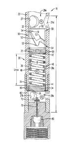
well completion apparatus can then be safely retrieved from the wellbore,
without
triggering the explosive event.
[0057] The present disclosure, in various embodiments, configurations and
aspects,
includes components, methods, processes, systems and/or apparatus
substantially
developed as depicted and described herein, including various embodiments, sub-
combinations, and subsets thereof. Those of skill in the art will understand
how to make
and use the present disclosure after understanding the present disclosure. The
present
disclosure, in various embodiments, configurations and aspects, includes
providing devices
19
CA 3024982 2018-11-22
CWCAS-523
and processes in the absence of items not depicted and/or described herein or
in various
embodiments, configurations, or aspects hereof, including in the absence of
such items as
may have been used in previous devices or processes, e.g., for improving
performance,
achieving case and/or reducing cost of implementation.
[0058] The phrases "at least one", "one or more", and "and/or" are open-
ended
expressions that are both conjunctive and disjunctive in operation. For
example, each of
the expressions "at least one of A, B and C", "at least one of A, B, or C",
"one or more of
A, B, and C", "one or more of A, B, or C" and "A, B, and/or C" means A alone,
B alone,
C alone, A and B together, A and C together, B and C together, or A, B and C
together.
[0059] In this specification and the claims that follow, reference will be
made to a
number of terms that have the following meanings. The terms "a" (or "an") and
"the" refer
to one or more of that entity, thereby including plural referents unless the
context clearly
dictates otherwise. As such, the terms "a" (or "an"), "one or more" and "at
least one" can
be used interchangeably herein. Furthermore, references to "one embodiment",
"some
embodiments", "an embodiment" and the like are not intended to be interpreted
as
excluding the existence of additional embodiments that also incorporate the
recited
features. Approximating language, as used herein throughout the specification
and claims,
may be applied to modify any quantitative representation that could
permissibly vary
without resulting in a change in the basic function to which it is related.
Accordingly, a
value modified by a term such as "about" is not to be limited to the precise
value specified.
In some instances, the approximating language may correspond to the precision
of an
instrument for measuring the value. Terms such as "first," "second," "upper,"
"lower" etc.
are used to identify one element from another, and unless otherwise specified
are not meant
to refer to a particular order or number of elements.
[0060] As used herein, the terms "may" and "may be" indicate a possibility
of an
occurrence within a set of circumstances; a possession of a specified
property,
characteristic or function; and/or qualify another verb by expressing one or
more of an
ability, capability, or possibility associated with the qualified verb.
Accordingly, usage of
CA 3024982 2018-11-22
CWCAS-523
"may" and "may be" indicates that a modified term is apparently appropriate,
capable, or
suitable for an indicated capacity, function, or usage, while taking into
account that in some
circumstances the modified term may sometimes not be appropriate, capable, or
suitable.
For example, in some circumstances an event or capacity can be expected, while
in other
circumstances the event or capacity cannot occur - this distinction is
captured by the terms
"may" and "may be."
[0061] As used in the claims, the word "comprises" and its grammatical
variants
logically also subtend and include phrases of varying and differing extent
such as for
example, but not limited thereto, "consisting essentially of" and "consisting
of." Where
necessary, ranges have been supplied, and those ranges are inclusive of all
sub-ranges
therebetween. It is to be expected that variations in these ranges will
suggest themselves to
a practitioner having ordinary skill in the art and, where not already
dedicated to the public,
the appended claims should cover those variations.
[0062] The foregoing discussion of the present disclosure has been
presented for
purposes of illustration and description. The foregoing is not intended to
limit the present
disclosure to the form or forms disclosed herein. In the foregoing Detailed
Description for
example, various features of the present disclosure are grouped together in
one or more
embodiments, configurations, or aspects for the purpose of streamlining the
disclosure.
The features of the embodiments, configurations, or aspects of the present
disclosure may
be combined in alternate embodiments, configurations, or aspects other than
those
discussed above. This method of disclosure is not to be interpreted as
reflecting an
intention that the present disclosure requires more features than are
expressly recited in
each claim. Rather, as the following claims reflect, the claimed features lie
in less than all
features of a single foregoing disclosed embodiment, configuration, or aspect.
Thus, the
following claims are hereby incorporated into this Detailed Description, with
each claim
standing on its own as a separate embodiment of the present disclosure.
[0063] Advances in science and technology may make equivalents and
substitutions
possible that are not now contemplated by reason of the imprecision of
language; these
21
CA 3024982 2018-11-22
CWCAS-523
variations should be covered by the appended claims. This written description
uses
examples to disclose the method, machine and computer-readable medium,
including the
best mode, and also to enable any person of ordinary skill in the art to
practice these,
including making and using any devices or systems and performing any
incorporated
methods. The patentable scope thereof is defined by the claims, and may
include other
examples that occur to those of ordinary skill in the art. Such other examples
are intended
to be within the scope of the claims if they have structural elements that do
not differ from
the literal language of the claims, or if they include equivalent structural
elements with
insubstantial differences from the literal language of the claims.
22
CA 3024982 2018-11-22