Note: Descriptions are shown in the official language in which they were submitted.
CA 03025012 2018-11-20
WO 2017/218941
PCT/US2017/037952
1
INTEGRATED CARD READER
Background of the Invention
1. Field of the Invention
The present invention relates to door entry handles which include an
integrated
card reader.
2. Description of Related Art
Conventional readers for RFID card or other wireless signal transmitting
devices
used to authenticate a user's entry are mounted on a wall adjacent a door or
on the
surface of the door itself. Such mountings present difficulties for particular
types of
doors, for example, glass doors, which necessitates the mounting of additional
hardware on the glass surface.
Summary of the Invention
Accordingly, there is a need for a simplified and effective mounting of a
reader for
RFID card or other wireless signal transmitting devices on doors, particularly
glass
doors.
Bearing in mind the problems and deficiencies of the prior art, it is
therefore an
object of the present invention to provide a system for allowing access
through a
glass door using a wireless identification key and receiver, the receiver
located
within a door handle pull on the door.
It is another object of the present invention to provide a wireless
identification
receiver within a door pull or handle of a door.
A further object of the invention is to provide a system for allowing access
through
a glass door using a wireless identification key and receiver, including a
circuit
located in the handle of the door capable of receiving an identification code
from a
key a user and transmitting a signal to a door locking mechanism.
CA 03025012 2018-11-20
WO 2017/218941
PCT/US2017/037952
-2-
It is yet another object of the present invention to provide a door or
building access
system or a method of using the door or building access system which allows a
user
wireless access through a glass door with the transmitter/receiver circuit
located on
or within the door handle secured to the glass pane of the door.
It is still another object of the present invention to provide door or
building access
which allows a user wireless access through a glass door without the wireless
access circuit being visible on or within the glass panes of the door.
It is another object of the present invention to provide door or building
access
which allows a user wireless access through a set of glass door having side
glass
panes without the wireless access circuit being visible on or within the glass
panes
of the door or glass side panels.
Still other objects and advantages of the invention will in part be obvious
and will
in part be apparent from the specification.
The above and other objects, which will be apparent to those skilled in the
art, are
achieved in the present invention which is directed to a door entry system for
operating a door using a wireless transmitter device containing identification
credentials of a user. The system includes a door operable by an uncoupling or
releasing securing mechanism, a door controller capable of operating the
uncoupling or releasing securing mechanism and a door handle for grasping by
the
user to operate the door, the handle having a cavity, the handle being secured
to
the door and spaced away from a surface thereof. The system includes a
wireless
device reader disposed in the handle cavity and a power source connected to
the
card reader. The wireless transmitter may be presented in the vicinity of the
reader
in the door handle and, upon verification of the credentials transmitted from
the
wireless transmitter device, the reader sends a signal to the door controller
to
uncouple or release the securing mechanism and permit the door to open. The
door may be a glass door. The door entry system may include a second door
operable by a manual securing system. The door entry system may include a
CA 03025012 2018-11-20
WO 2017/218941
PCT/US2017/037952
-3-
second door having a second securing mechanism operable by the door
controller.
The glass door may include a rail at the top or bottom of the door, the rail
having a
latching device with a retractable latchbolt extending therefrom into a strike
disposed in the door frame or floor adjacent latching device, the door
operable by a
.. latch mechanism which retracts the latchbolt in response to a command from
the
wireless card reader. The glass door may include a rail at the top or bottom
of the
door, the rail having a latching device with a retractable latchbolt extending
therefrom into a strike disposed in the door frame or floor adjacent latching
device,
the door operable by an electric strike mechanism which opens the strike in
response to a command received at a strike controller from the card reader.
The
door handle may be an elongated cylindrical handle. The power source may be a
battery or a rechargeable battery and charging system. The charging system may
include a solar cell or induction charger.
Another aspect of the invention is directed to a door pull comprising an
elongated
handle having a cavity and a handle portion securable to a door, a wireless
card
reader disposed in the handle cavity and a power source electronically
connected
to the card reader. The card reader may be in communication with a door
controller, the door controller capable of securing or releasing the glass
door to or
from a locked position. The wireless card reader may receive an authentication
signal from an authorized wireless transmitting device to transmit an
authorization
signal to a door controller allowing the door to be released from a locked
state.
The door pull may include a wireless antenna disposed in the handle cavity and
the
power source may be disposed in the handle cavity, the power source wired to
power the card reader and antenna, wherein the wireless card reader receives a
signal from an authorized card and the antenna relays an authorization signal
to an
access control which releases the glass door from a locked state.
Another aspect of the invention is directed to a method for operating a door
using a
wireless transmitter. The method includes providing a door operable by a
releasing
securing mechanism, a door controller capable of operating the releasing
securing
CA 03025012 2018-11-20
WO 2017/218941
PCT/US2017/037952
-4-
mechanism and a door handle for grasping by a user to operate the door, the
handle having a cavity, the handle being secured to the door and spaced away
from
a surface thereof. The method includes providing a reader disposed in the
handle
cavity and a power supply connected to the card reader and a wireless
transmitting
device capable of communication with the reader. The method includes
presenting
the wireless transmitter device in the vicinity of the reader in the door
handle and
wirelessly transmitting credentials from the wireless transmitting device. The
method includes upon verification of the credentials transmitted from the
wireless
transmitting device, sending a signal from the reader to the door controller
to
uncouple or release the securing mechanism and permitting the door to open.
The
door controller and securing mechanism may be disposed on a top or bottom rail
of
the door and the card reader may be capable of sending a signal to the door
controller to allow the door controller to activate or deactivate the securing
mechanism. The door controller and securing mechanism may be disposed in the
door a door frame encompassing the door with a strike disposed in a rail
disposed
on the door. The card reader may be capable of sending a signal to the door
controller to allow the door controller to activate or deactivate the securing
mechanism. The device reader may be a wireless RFID reader. The door may be a
glass door allowing building access and the entry system may allow a user
wireless
access through the glass door without the wireless access circuit being
visible on or
within the glass panes of the door. The door may be a pair of glass doors with
a
stationary glass pane on at least one side of the pair of glass doors whereby
the
entry system allows a user wireless access through the glass doors without the
wireless access circuit being visible on or within the at least one stationary
glass
pane.
Brief Description of the Drawings
The features of the invention believed to be novel and the elements
characteristic of
the invention are set forth with particularity in the appended claims. The
figures are
for illustration purposes only and are not drawn to scale. The invention
itself,
CA 03025012 2018-11-20
WO 2017/218941
PCT/US2017/037952
-5-
however, both as to organization and method of operation, may best be
understood
by reference to the detailed description which follows taken in conjunction
with the
accompanying drawings in which:
Fig. 1 is a perspective view of a pair of glass doors having an embodiment of
the
door entry handle with an integrated card reader of the present invention.
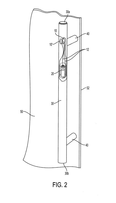
Fig. 2 is a close-up perspective view, partially cut away, of a door entry
handle with
integrated card reader of Fig. 1.
Fig. 3 is a cross-sectional view of the door entry handle showing the
integrated card
reader of Fig. 1.
Fig. 4 is a cross-sectional view of a latching mechanism that may be employed
on
the glass door of Fig. 1 with the integrated card reader of the present
invention.
Fig. 5 is a perspective view of an embodiment of a battery pack at the end of
a door
entry handle that may power the integrated card reader of the present
invention.
Description of the Preferred Embodiment(s)
In describing the preferred embodiment of the present invention, reference
will be
made herein to Figs. 1-5 of the drawings in which like numerals refer to like
features of the invention.
The present invention allows controlled access into a building or enclosed
area
while minimally impacting the appearance and structure of the entrance door.
An
embodiment of the invention is employed in an all glass entranceway or other
entryway where aesthetics are important and would be highly valued by
architects.
Access through the door would be given to a user having a proper RFID card or
other wireless signal transmitting device in their possession.
The reader for the RFID or other wireless reader device may be integrated into
the
handle or pull used to open and close the door. In the embodiment shown in
Figs.
CA 03025012 2018-11-20
WO 2017/218941
PCT/US2017/037952
-6-
1 and 2, an all glass entryway comprises glass walls or glass side panes 70,
72
within which are mounted glass doors 50, 50'. In one example, one door 50 may
include the wireless door entry system while the other door 50' is operable by
a
manual securing system, or the doors 50, 50' may both be operable by a door
controller in communication with the wireless reader device. An elongated door
pull or other type of handle includes a hollow tube main body 30, an
integrated,
battery powered wireless reader 10 and a handle connector portion 40 secured
to
the exterior of glass door 50 adjacent swinging free edge 52. The door handle
or
pull as shown in the cutaway view of Fig. 2 may be a hollow cylindrical or
other
shape tube 30 with end caps 30a, 30b secured to the hollow tube. The handle
connector portion 40 may be perpendicular to the tube or handle 30 to secure
to
the face of the door 40 and space the handle from the surface of door 50 a
distance
sufficient to enable users to wrap their hands around and grasp the tube 30.
The
wireless reader 10 as shown may be disposed inside the hollow handle at a mid-
point between upper and lower ends 30a, 30b and includes a bezel which may be
secured, e.g., by snapping in a compression fit, so that face 10' is disposed
on the
surface of the hollow tube 30. The face 10' in the embodiment shown is of
cylindrical configuration to match the tube 30. The face 10' configuration may
be
shaped to conform to the exterior of other tube configurations, e.g., oval, or
flat for
rectangular or square. Alternatively, the wireless reader 10 may be disposed
in the
edge of the top end 30a of the door pull 30 if door pull end is located at a
convenient height for users, making it less visible in the door pull. The
wireless
reader assembly 10, 10', and 20 may also be constructed in a one piece design
to
be located on the top end of the handle. Placement of the card reader 10
inside the
hollow tube eliminates the visibility of a separate card reader in an all
glass
entryway, such as that shown in Fig. 1. For longer door pulls where the top of
the
pull is not easily accessible, the reader may be disposed in a central or
lower
portion of the pull and wired to a top edge that may secure the battery 20.
The
door pull may alternately include a rechargeable battery including a charging
system such as a solar cell or induction charger.
CA 03025012 2018-11-20
WO 2017/218941
PCT/US2017/037952
-7-
The wireless RFID or other device reader is shown disposed entirely within
tubular
handle 30 in Fig. 3. The reader 10 includes within housing 18 controller
circuitry
16 in communication with an RFID transmitter/receiver located in face 10', and
a
transmitting antenna 14 for Wi-Fi or other radio signal. In the case of a
passive
.. RFID card or other device 90, transmitter/receiver 10' sends an inductive
interrogator signal 102, which then causes an authentication reply signal 104
to be
emitted from RFID device 90. Controller 16 determines whether signal 104 is
from
an authorized device, in which case it may cause signal 106 to be transmitted
to a
door controller or other device.
A plurality of conductors 12 electrically connect the battery 20 to the card
reader
10. As shown in Fig. 5, battery 20 may be located inside a battery pack 22
that is
configured with an end cap 32 of tube 30. Alternately, a solar charger 24
located
on a surface of handle 30 may charge a rechargeable battery to power the card
reader 10, so less maintenance would be required.
Door 50 as shown includes a wirelessly controlled door latching system, as
shown
in Fig. 4, which provides an uncoupling / releasing securing mechanism. Door
50
includes a sill or rail 58, at the top or bottom of the door, having a
latching device
56 with a retractable latchbolt 57 extending therefrom into strike 60, located
in the
door frame 62 or floor adjacent latching device 56. The door may be unlocked
either by use of a latch mechanism 56 which retracts latchbolt 57 in response
to a
command from latch controller 70 or an electric strike mechanism 60 which
opens
the strike in response to a command from strike controller 80.
In use, users would place their unique RFID card or other wireless signal
transmitting device 90 near the card reader face 10' where it may be powered
by an
inductive signal from the reader 10 to emit proper credentials from the
antenna in
the form of a signal 104. Alternately, the unique device 90 may be self-
powered to
send out a signal 104, or may not need power to relay the card code signal to
the
reader 10. This signal 104 from device 90 would be sent to a Wi-Fi or other
wireless hub which is tied into the access control system, disposed in or
otherwise
CA 03025012 2018-11-20
WO 2017/218941
PCT/US2017/037952
in communication with latch controller 70 and/or strike controller 80. The
access
control system determines if the signal is one that is permitted access to
that
opening. If access is granted, the access control system unlocks the door
securing
mechanisms (strike 60 or latching device 56) allowing the user to enter.
.. A method for using the system may include presenting the wireless
transmitter
device 90 in the vicinity of the reader 10 in the door handle and wirelessly
transmitting credentials from the wireless transmitting device. Upon
verification of
the credentials transmitted from the wireless transmitting device 90, a signal
is sent
from the reader 10 to the door controller or latching device 56 to uncouple or
release the securing mechanism, permitting the door to open. The door
controller
and securing mechanism may be disposed on a top or bottom rail of the door and
the card reader is capable of sending a signal to the door controller to allow
the
door controller to activate or deactivate the securing mechanism. Alternately,
the
door controller and securing mechanism may be disposed in the door a door
frame
encompassing the door with a strike disposed in the rail on the door and the
card
reader sends the signal to the door controller to allow the door controller to
activate
or deactivate the securing mechanism.
Thus, the present invention provides a system for allowing access through a
glass
door using a wireless identification key and receiver, the receiver located
within a
door handle pull on the door and a wireless identification receiver within a
door
pull or handle of a door. The present invention also provides a system for
allowing
access through a glass door using a wireless identification key and receiver,
including a circuit located in the handle of the door capable of receiving an
identification code from a key a user and transmitting a signal to a door
locking
mechanism. The present invention also provides a door or building access
system
and a method of using the door or building access system which allows a user
wireless access through a glass door with the transmitter/receiver circuit
located on
or within the door handle secured to the glass pane of the door so the
wireless
access circuit is not visible on or within the glass panes of the door. The
present
CA 03025012 2018-11-20
WO 2017/218941
PCT/US2017/037952
-9-
invention also provides the wireless access circuit not being visible on or
within
glass side panels of the doors.
While the present invention has been particularly described, in conjunction
with a
specific preferred embodiment, it is evident that many alternatives,
modifications
and variations will be apparent to those skilled in the art in light of the
foregoing
description. It is therefore contemplated that the appended claims will
embrace
any such alternatives, modifications and variations as falling within the true
scope
and spirit of the present invention.
Thus, having described the invention, what is claimed is: