Note: Descriptions are shown in the official language in which they were submitted.
CA 03025027 2018-11-21
WO 2017/215734 PCT/EP2016/063581
-1-
Rotatable Feed Distributor
15
Field of invention
The present invention relates to a rotatable feed distributor for a crusher,
and in particular
although not exclusively, to a feed distributor for a gyratory crusher
configured to
manipulate a feeding supply of crushable material into an inlet region of the
crusher.
Background art
Generally, a belt conveyor or feeder delivers rocks and stones into a crusher.
The rocks
ride up the conveyor, whose end is located above the input of the crusher and
then fall
under gravity into the crusher where they are broken to a predetermined size.
Typically, the
uncrushed rocks pass initially through a feed distributor, which assists in
dispensing the
rocks into the crusher.
Since rocks fed into the crusher are not always of the same size and shape,
they will not
necessarily be reduced to a final desired and uniform size. However, it is
preferable to
CA 03025027 2018-11-21
WO 2017/215734 PCT/EP2016/063581
-2-
obtain the crushed rocks within a relative size range, otherwise the material
may require
further processing. Furthermore, the final crushed rock product should
preferably have a
uniform size and shape gradation, rather than having a batch of stones that
may contain
very fine dust as a product and another batch that only contains larger rocks.
Such rock
segregation is disadvantageous as it can lead to a less saleable end product.
A variety of different feed distributors have been proposed with examples
described in US
7,040,562; US 6,227,472; US 4,106,707; and US 3,212,720. However premature
wear of
specific parts of existing feed distributors is a continuous problem. In
particular, when
rocks fall upon the distributor and in particular a distributor chute, the
impact tends to wear
and erode specific components. Additionally, the rock crushing environment
creates
excess and abrasive dust which can also cause premature wear of certain
machine
elements, such as bearings. As a result feed distributor components require
regular
replacement and maintenance, which increases downtime of the crushing system
and
consequently reduces the efficiency of the overall system.
US 7,040,562 and US 8,056,847 describe rotating feed distributors that provide
improved
resistance to the impacting forces and abrasive dust resulting from the
transfer of the
crushable material. However, the problems of excessive wear due to dust and
particulate
contamination within the internal region of the distributor remains
problematic.
Accordingly, there is a need for a feed distributor that addresses these
problems.
Summary of the Invention
It is an objective of the present invention to provide a feed distributor for
a crusher and in
particular a gyratory crusher that is effective to distribute and dispense a
flow of crushable
material into a crusher so as to optimise the distribution of material fed
into the crushing
zone whilst providing a distributor that is effectively robust against the
dust and debris
laden environment within which the distributor is typically operative. It is a
further
specific objective to provide a distributor that requires reduced maintenance
and is
configured to protect internal component, in particular moving parts and
surfaces, so as to
extend the longevity of the distributor working parts and in turn minimise
system
CA 03025027 2018-11-21
WO 2017/215734 PCT/EP2016/063581
-3-
downtime.
The objectives are achieved by providing a feed distributor having a rotatable
chute
operating and mounted at a housing such that dust, debris or other particulate
matter is
prevented from being entrained into the housing (from the region of the chute)
that would
otherwise contaminate the internal working part zone within the housing and
within which
the various drive and bearing components are located to drive and stabilise
the rotating
motion of the chute.
In particular, and according to one aspect, a feed distributor is provided
comprising at least
one seal ring or a plurality of seal rings located at one or a plurality of
regions between the
chute and parts of the housing. The seal rings provide an effective physical
barrier to the
ingress of particulates at specific locations between the chute and housing.
According to
further aspects, a feed distributor is provided that is capable of creating a
positive pressure
within the working part zone (defined by the housing) such that dust and
debris ingress
into the working part zone is inhibited or preferably prevented by an exhaust
air flow
stream flowing from the region of the working part zone to exhaust from
between selected
regions of the rotatable chute and housing. In certain aspects, a distributor
is provided with
a combination of at least one sealing ring and an air feed assembly
(communicating with
and providing the positive pressure at the working part zone) such that dust
and debris
ingress into the working part zone is prevented by a combination of such seals
and the
positive pressure (air flow and exhaust).
Preferably, the present feed distributor is intended to sit beneath the top
end or output end
of a conveyor or feeder used in conjunction with a rock crusher. The conveyor
or feeder is
capable of delivering rocks from a supply source to the distributor that is
positioned over
the crusher. The present feed distributor is configured to receive the rocks
onto a feed
platform, where the rocks travel from the feed platform into a feed chute
comprising an
inlet and an outlet. Optionally, the feed chute may have an outer tube and an
inner tube,
with the outer tube configured to rotate and the inner tube being relatively
stationary. The
outer tube may be driven by a motor coupled to a gear mechanism. The use of
two tubes
reduces the wear on the feed distributor as the rotating outer tube allows the
rocks to be
CA 03025027 2018-11-21
WO 2017/215734 PCT/EP2016/063581
-4-
evenly distributed into the crusher which in turn minimises rock size
segregation, which
improves the crusher efficiency and reduces operating costs.
The present feed distributor provides for an even distribution of the rocks
before entering
the crusher, thereby minimizing uneven rock build-up within the crusher and
further
minimizing the need for recycling or re-crushing of rocks that are not crushed
within
predetermined size limitations. The present feed distributor is configured
specifically via
the at least one seal ring and/or positive pressure within the working part
zone to protect a
power means, a support means and drive system (encompassing bearings, bearing
surfaces,
drive belts, belt surfaces, pulleys, gears and other working components and
surfaces) from
abrasive dust and other rock particles, thereby reducing the overall wear on
the feed
distributor. The arrangement of the seal ring and/or positive air pressure
protected working
part zone provides for a reliable and low maintenance drive and chute support
system.
Optionally, the feed distributor comprises a sheave coupled around the
rotating outer tube
(chute). The sheave may comprise a flange and a face, the flange and face
being
perpendicular to one another. The sheave structure may be supported on its
flange by a
plurality of thrust bearings mounted to the feed distributor housing.
Accordingly the
rotating outer tube is preferably supported by the thrust bearings. The sheave
is configured
to receive one or more drive belts driven by a power means, such as a motor
and gear
reducer assembly. A distance between the power means and rotating outer tube
may be
maintained by a plurality of roller bearings circumferentially arranged about
the sheave.
According to a first aspect of the present invention there is provided a
rotating feed
distributor for a crusher comprising: a housing defining an internal working
part zone; a
rotatable chute to receive crushable material to be fed to a crusher, the
chute defining at
least part of an internal bore provided with an inlet and an outlet; a sheave
provided
externally at and rotatably coupled with the chute; a power means and drive
transmission
mounted within the working part zone, at least part of the drive transmission
coupled to the
sheave to provide rotation of the chute relative to the housing; characterised
by: at least
one seal ring provided at the chute to at least partially close a gap region
between the chute
and a part of the housing and inhibit ingress of dust into the working part
zone.
CA 03025027 2018-11-21
WO 2017/215734 PCT/EP2016/063581
-5-
Preferably, the housing comprises an inlet aperture and an outlet aperture in
fluid
communication with the working part zone to allow the crushable material to
pass through
the housing and into the internal bore, the chute projecting trough at least
the outlet
aperture and at least partially into the working part zone.
Preferably, at least a first seal ring is provided between the inlet of the
chute and a part of
the housing that defines the inlet aperture. Optionally, the first seal ring
is positioned
within the working part zone and is positioned against an internal facing
surface of the
.. housing that defines the working part zone. Optionally, at least a second
seal ring is
provided between the chute and a part of the housing that defines the outlet
aperture.
Optionally, the second seal ring is positioned externally to the working part
zone and
against an external facing surface of the housing relative to the working part
zone. The
seal rings may be positioned directly or indirectly (via an intermediate
gasket) against the
housing.
Within this specification reference to the chute and housing having a
respective inlet and
outlet is with regard to a flow of crushable material through the distributor
as the
distributor supplies material to the crusher.
Preferably, a first seal ring is provided at a first region of the chute to
provide at least
partial closure of a first gap region between the first region of the chute
and a first part of
the housing that is internal facing relative to the working part zone.
Preferably, a second
seal ring provided at a second region of the chute to provide at least partial
closure of a
second gap region between the second region of the chute and a second part of
the housing
that is external facing relative to the working part zone.
Preferably, the first seal ring is positioned at or towards the inlet of the
chute and the
second seal ring is spatially separated from the first seal ring and is
positioned between the
first seal ring and the outlet of the chute.
Preferably, the at least one seal ring comprises an annular main body and a
flexible annular
CA 03025027 2018-11-21
WO 2017/215734 PCT/EP2016/063581
-6-
flange projecting from the main body. Preferably, the at least one seal ring
comprise a V-
ring seal.
Preferably, the distributor comprises at least one clamp to radially compress
against the at
least one seal ring and secure the seal ring at an external facing surface of
the chute such
that the seal ring is rotatably coupled to the chute.
Optionally, the chute comprises a radially outward projecting shoulder to abut
the seal ring
or comprises a radially inward projecting groove at an outward facing surface
of the chute
to at least partially receive the seal ring. The groove or shoulder is
configured to assist the
clamp (secured around the seal ring), maintain the desired position of the
seal ring at the
outward facing surface of the chute. Where the chute comprises a shoulder to
help seat the
seal ring, the shoulder does not project radially outward from the outward
facing surface to
an extent that would other inhibit or prevent the seal ring from being axially
slid over the
outward facing surface from the chute outlet towards the chute inlet.
Preferably, the distributor comprises an air feed assembly coupled in fluid
communication
with the working part zone to provide a supply of air into the working part
zone.
Preferably, the air feed assembly comprises ducting and any one of a fan, a
compressor or
pneumatic system to generate an air flow stream through the ducting and into
the working
part zone.
According to a second aspect of the present invention there is provided a
rotating feed
distributor for a crusher comprising: a housing defining an internal working
part zone; a
rotatable chute to receive crushable material to be fed to a crusher, the
chute defining at
least part of an internal bore provide with an inlet and an outlet; a sheave
provided
externally at and rotatably coupled with the chute; a power means and drive
transmission
mounted within the working part zone, at least part of the drive transmission
coupled to the
sheave to provide rotation of the chute relative to the housing; characterised
by: an air feed
assembly coupled in fluid communication with the working part zone to provide
a supply
of air into the working part zone, the air capable of exhausting from the
working part zone
from at least a region between the chute and the housing to inhibit ingress of
dust into the
CA 03025027 2018-11-21
WO 2017/215734
PCT/EP2016/063581
-7-
working part zone.
According to a third aspect of the present invention there is a provided a
gyratory crusher
comprising a feed distributor as described and claimed herein.
Brief description of drawings
A specific implementation of the present invention will now be described, by
way of
example only, and with reference to the accompanying drawings in which:
Figure 1 is a side view of the present invention in combination with a rock
crusher and a
feed conveyor;
Figure 2 is a perspective view of the present invention;
Figure 3 is a bottom plan view of the present invention;
Figure 4 is a sectional side view of the present invention taken along line 4-
4 of figure 3;
Figure 5 is a partial cut away sectional side view;
Figure 6 is another partial cut away section side view;
Figures 7 and 8 are sectional side views of the present invention, feedbox and
rocks;
Figure 9 is overhead view of a crusher used in connection with the present
invention;
Figure 10 is a cross sectional perspective view through the chute section of
the distributor;
Figure 11 is an underside cross sectional perspective view of the distributor
of figure 10;
Figure 12 is a cross sectional perspective view of a first seal ring mounted
between the
CA 03025027 2018-11-21
WO 2017/215734
PCT/EP2016/063581
-8-
chute and housing of figure 11;
Figure 13 is a cross sectional perspective view of a second seal ring mounted
between the
chute and housing of the distributor of figure 11;
Figure 14 is a further cross sectional perspective view of the feed
distributor.
Detailed description of preferred embodiment of the invention
Figure 1 shows a side view of a rock crushing system 10 employing the present
invention.
A plurality of rocks 12 is fed upwards on a conveyor 14. The conveyor 14
delivers the
rocks 12 through a feedbox 16 and into an improved feed distributor 18, which
is the focus
of the present invention. The feed distributor 18 is designed for 360 degree
rotation and
delivers the rocks 12 uniformly to the crusher 20. The distributor 18 may be
mounted to
the crusher 20, the conveyor 14, or may be mounted independently. A frame or
mount 19
holds the feed distributor 18 in place over the crusher 20. The frame 19 can
encompass a
wide range of shapes and sizes that will adequately mount the distributor 18
over the
crusher 20. The feedbox 16 should be considered a stand-alone feature that is
not part of
the present invention. The feed distributor 18 passes the rocks 12 into the
crusher 20,
which rotates or gyrates and crushes the rocks 12. The crushed rocks 12 exit
below the
crusher 20, possibly onto a second conveyor 22, which will then take the
crushed rocks 12
away to be used, further sorted, or to be recycled and reprocessed in the rock
crushing
system 10.
Figure 2 shows a perspective view of the improved feed distributor 18. A power
means,
such as electric motor 24 of any sufficient design or size that will
adequately allow the
distributor 18 to operate powers the feed distributor 18. The output of the
motor 24 is
rotationally coupled to a gear reducer 24a, which in turn drives the rotating
components of
the feed distributor 18.
The feed distributor 18 has three main areas that the rocks will encounter
when proceeding
towards the crusher 20: a feed platform or box 26, an inlet 28, and an outlet
30. The inlet
CA 03025027 2018-11-21
WO 2017/215734 PCT/EP2016/063581
-9-
28 and the outlet 30 generally are opposing sections of a tubular chute 32
containing a
coextensive bore within the chute 32, which will be described in more detail
with respect
to the subsequent figures. When rocks 12 enter into the distributor 18, as
shown in Figure
1, the rocks 12 fill up the feed platform 26 and some of them drop into the
inlet 28. After
enough rocks have accumulated on the platform 26, all of the rocks 12 will
pass into the
inlet 28, further traveling through to the outlet 30, where they will
eventually end up in the
crusher 20. The inlet 28 includes a reinforced lip 34, which helps to extend
the life of the
inlet 28. Similarly, a second lip 36 is located around the outlet 30 to also
extend the life of
the outlet 30 (see Figure 2). The lips 34 and 36 may be designed in any
fashion, such as
from a metal rod or similar material that may be welded to the inlet 28 and
the outlet 30,
which will reduce wear on the inlet 28 and outlet 30.
Again referring to Figure 2, the feed distributor 18 comprises a housing 38,
which prevents
dust and other debris from interfering with mechanical components of the feed
distributor
18. The housing 38 may be of any shape that will efficiently protect the
internal
components and not interfere with the functions of the distributor 18.
Preferably, the
housing 38 is designed so that it substantially seals off the inner parts of
the distributor 18
from the outside elements. A plurality of brackets 40 is provided on the
outside of the
housing 38. The brackets 40 provide an area for the distributor 18 to be
mounted onto the
frame 19 over the crusher 20 (see Figure 1). The brackets 40 should be
understood to
encompass any mounting means that will sufficiently secure the distributor 18
to the
crusher 20. Similarly, the brackets 40 together with the frame 19 may be of
any design. For
instance, the distributor 18 does not necessarily need to be firmly bolted
down, but may be
held in place with stop blocks (not shown).
The inlet 28 and the outlet 30 comprise the tubular chute 32. Located within
the inlet 28 is
an optional stationary tube or wear sleeve 62. The stationary tube or wear
sleeve 62
preferably extends a distance above the inlet 28 and also a distance below the
inlet 28. The
reinforced lip 34 formed along the upper edge of the wear sleeve 62 helps to
extend the life
of the inlet 28. When the wear sleeve 62 is employed in the feed distributor
18, the
previously described lip 34 is located at the top of the wear sleeve 62. While
the wear
sleeve 62 may be secured to the inlet 28, it preferably rests upon the feed
platform 26. A
CA 03025027 2018-11-21
WO 2017/215734 PCT/EP2016/063581
-10-
laterally extending flange 64 assists in the wear sleeve 62 resting on the
feed platform 26.
When it becomes worn down, the wear sleeve 62 may be easily removed and
replaced with
a new sleeve.
Figure 3 shows a bottom view of the improved feed distributor 18. The output
shaft 72 of
gear reducer 24a (shown in phantom) is coupled to one or more drive wheels,
sheaves, or
pulleys 50, which is connected to one or more drive belts 52. Drive belts 52
are engaged
with sheave 50 and with sheave structure 54. An air feed assembly indicated
generally by
reference 83 is mounted at housing 38 so as to be provided in fluid
communication with an
internal region of housing 38 referred to herein as a working part zone 29
(that is defined
by housing 38 and in which the various drive transmission components 24a, 50,
52, 54,
100 etc., are housed. Further details of the air feed assembly 83 is described
with reference
to figure 14 below.
As shown in Figure 4, the sheave structure 54 is attached to the tubular chute
32. The drive
belts 52 are received into belt receiving grooves 56 on the sheave structure
54. The drive
belts 52 are preferably V-belts. The drive belts 52 are tightened by adjusting
the distance
between the sheave 50 and the sheave structure 54. Once the position of the
tubular chute
32 is set (as described below) belt tightening is accomplished by means of
slotted openings
59 being formed in the mounting for the gear reducer 24a and motor 24
assembly.
As also shown in Figure 3, the force exerted by the belts 52 about the sheave
structure 54
and tubular chute 32 is countered by a pair of idler wheel assemblies 80. Each
idler wheel
assembly 80 is mounted to the underside of feed platform 26. An idler wheel 86
is
rotationally supported by an axle between upper and lower idler brackets. A
fastener 92
passes through an offset opening in each of the idler brackets and the feed
platform 26 to
allow the assemblies 80 to pivot on the feed platform about the axis of the
fastener 92.
Once the tubular chute 32 is properly positioned within the feed distributor
18, each idler
wheel assembly 80 is pivoted such that its idler wheel 86 comes into contact
with the face
55 of the sheave structure 54 which is in turn coupled to the tubular chute
32. While not
required, a cover 94 may extend about each idler wheel 86 to prevent the build-
up of dust
and other materials that may adversely affect the performance of the rollers
86 and their
CA 03025027 2018-11-21
WO 2017/215734 PCT/EP2016/063581
-11-
bearings 88.
Tubular chute 32 is vertically supported by at least three thrust bearings
100. Each bearing
100 has a bearing surface 102 formed from a composite material commercially
known as
PEEK. Bearing surfaces 102 support the flange 58 formed on the sheave
structure 54 that
is coupled to the tubular chute 32.
The platform 26, as shown in Figure 4, preferably has a square shape, with the
inlet 28 and
the wear sleeve 62 centered within the platform 26. The height of the platform
26 is shown
as being approximately the same height that the wear sleeve 62 extends
upwardly from the
inlet 28. However, any height that will allow the platform 26 to operate as a
rock bed for
the feed distributor 18 will suffice.
Further in Figure 4, the outlet 30 has a base 66, an open side 68, and at
least one closed
side 70. The open side 68 and the closed side or sides 70 extend laterally
upward from the
base 66. Preferably, the closed side 70 has a curvilinear shape (see Figures 2
and 3), which
prevents rocks from unnecessarily building up in the comers of the outlet 30.
However, the
outlet 30 may have straight sides 70, forming such other geometric shapes, and
still fall
within the scope of the invention. The outlet 30 is relatively large, thereby
increasing
throughput capacity of the distributor 18. Referring further to Figure 4, the
motor 24 and
the gear reducer 24a are shown connected to the output shaft 72, which drives
the drive
wheel or sheave 50. The drive wheel 50 rotates the drive belts 52, which pass
around the
sheave structure 54 coupled to the tubular chute 32, causing the chute 32 to
rotate. As the
chute 32 rotates, the wear sleeve 62 preferably remains stationary, which
contributes to
even wear of the sleeve 62, thereby extending the life of the wear sleeve 62.
Figure 5 is a cross-sectional view depicting the relationship between the
stationary housing
38, rotating tubular chute 32, sheave structure 54 and a thrust bearing 100 in
greater detail.
As shown, the sheave structure 54 includes two grooves 56 for receiving the
drive belts 52
that rotate the chute 32. The drive belts 52 are preferably v-belts. Sheave
structure 54 also
includes a horizontal flange portion 58. The sheave structure 54 is coupled to
the chute 32
utilizing fasteners 60 as shown. The flange portion 58 has a smooth underside
surface that
CA 03025027 2018-11-21
WO 2017/215734 PCT/EP2016/063581
-12-
is supported on thrust bearings 100 at bearing surfaces 102. Each thrust
bearing 100 is
supported on a bearing block or support 104. The bearing blocks 104 are
affixed to housing
38. A lubricant line 106 supplies a lubricant, such as grease to the thrust
bearing surface
102. Fittings, such as grease fittings 108 are mounted outside the housing 38
so that the
.. thrust bearings 100 can be periodically lubricated without having to remove
any
components from the feed distributor 18.
While it has been found that the presence of lubricant reduces an audible hum
from the
feed distributor during operation, it is not necessary to supply lubricant to
any of the thrust
bearings 100 during operation of the feed distributor 18. In other words, the
performance
of the feed distributor remains the same with or without the presence of
lubricant at the
interface of the flange portion 58 and thrust bearing surface 102.
Housing 38 comprises a first mouth or aperture 11 provided at the region of
platform or
feedbox 26. Aperture 11 is generally circular and comprises a diameter being
larger than
an external diameter of sleeve 62 such that sleeve 62, having a generally
cylindrical
configuration, is capable of extending through aperture 11 and into a part of
the working
part zone 29 defined by housing 38. . Sleeve 62 comprises an inlet 15 and an
outlet 17
such that feed material is capable of flowing into the generally cylindrical
sleeve 62
through inlet 15 and to exit via outlet 17. Sleeve 16 is mounted at feedbox 26
so as to have
a degree of lateral play (in a radial direction relative to a central axis 79
of sleeve 62 and
rotatable chute 32). Housing 38 also comprises a second mouth or aperture 13
positioned
generally vertically below first aperture 11 and is generally co-aligned with
first aperture
11 to be centered on axis 79. Second aperture 13 is generally circular and
provides a
.. means of receiving and mounting rotatable chute 32 at the feed distributor.
In particular,
an uppermost axial end of chute 32 is received and extends beyond second
aperture 13 so
as to sit within a part of the working part zone 29. As will be appreciated, a
small radial
gap is provided between an external facing surface 24 of chute 32 and aperture
13 so as to
allow chute 32 to rotate relative to housing 38. Chute 32 comprises a
corresponding inlet
21 mounted within working part zone 29 (and immediately under feedbox 26) and
a
corresponding outlet 23 that corresponds to the feed distributor outlet 30.
Accordingly,
feed material is capable of flowing through sleeve 62 and into a bore 47
defined by an
CA 03025027 2018-11-21
WO 2017/215734 PCT/EP2016/063581
-13-
internal facing surface of rotatable chute 32 and then to exit from the feed
distributor via
chute outlet 23.
So as to prevent ingress of dust and particulate matter into working part zone
29, feed
distributor 18 comprises a first seal ring 35 and a second seal ring 37
positioned
respectively between a region of chute 32 and respective regions or parts of
housing 38
Within this specification, reference to the housing 38 encompasses the feedbox
26 and its
surfaces and components. In particular, each of the first and second seal
rings 35, 37 is
rotatably coupled to chute 32 and are respectively secured against an external
facing
surface of chute 32 at an axial upper half of chute 32 closest to chute inlet
21.
Figure 6 is an enlarged cross-sectional view of the relationship between idler
wheel
assembly 80 and the sheave structure 54. Each idler wheel assembly 80 is
mounted to the
underside of feed platform 26 (see also Figure 3). Each assembly 80 includes a
lower idler
bracket 82, an upper idler bracket 84, an idler wheel 86, a pair of ball
bearing assemblies
88, an axle 90 and a fastener 92. The idler wheel 86 is rotationally supported
by the axle 90
between the upper and lower idler brackets 84, 82. The fastener 92 passes
through an offset
opening in the idler bracket 82 and is fastened to the idler bracket 84
through a threaded
hole to allow the assemblies 80 to pivot on the base platform about the axis
of the fastener
92. Once the tubular chute 32 is properly positioned with respect to the
stationary tube 64
and within the feed distributor 18, each idler wheel assembly 80 is pivoted
such that its
idler wheel 86 comes into contact with the face 55 of the sheave structure 64
coupled to the
tubular chute 32. While not required, a cover 94 may extend about each idler
wheel 86.
As further shown in Figure 6, idler wheel 86 makes contact with the vertical
face 55 of
sheave structure 54 to maintain the predetermined distance between sheave 50
and rotating
chute 32 so that the chute is properly centered in the housing 38 and proper
tension is
maintained by the drive belts 52. It can also be seen that the face 55 of
sheave structure 54
is substantially orthogonal to the flange 58 of sheave structure 54.
Figure 7 shows a side view of the feed distributor 18 after rocks 12 have been
fed into the
feedbox 16. As previously shown in Figure 1, the feedbox 16 is located
directly over the
CA 03025027 2018-11-21
WO 2017/215734 PCT/EP2016/063581
-14-
platform 26. The feedbox 16 securely fits onto the platform 26 in a way that
will contribute
to the platform 26 acting as an accumulator or 'dead bed' 74 for the feed
distributor 18.
The dead bed 74 decreases wear on the feed distributor 18, the chute 32, and
the wear
sleeve 62. Because the rocks 12 build-up on the platform 26 as opposed to
constantly
falling down upon the chute 32 and the wear sleeve 62, the wear will be
reduced, as there
is rock on rock sliding, as opposed to rock on distributor sliding.
Figure 8 shows the distributor 18 of Figure 7 after more rocks 12 have been
fed into the
distributor 18. A second dead bed 76 is formed in the outlet 30, defined by
the base 66 and
the closed side 70. The second dead bed 76 further reduces wear on the chute
32 and the
base 66. Furthermore, the sloped shape of the dead bed 76 allows the rocks 12
to easily
exit the outlet 30 without unnecessary wear on the chute 32. However, the
rotation of the
chute 32 still provides that the rocks 12 are evenly distributed.
Figure 9 shows an overhead view of the crusher 20 and the chute 32. Because of
the
arrangement of the present design, the rocks 12 are evenly distributed
throughout the
crusher 20. Because the rocks 12 are fed into the crusher 20 with less size
segregation and
more uniformity, the crusher 20 will more efficiently crush the rocks 12.
Likewise, it is
advantageous that the chute 32 is centered over the crusher 20 for further
uniformity of the
.. fed rocks 12.
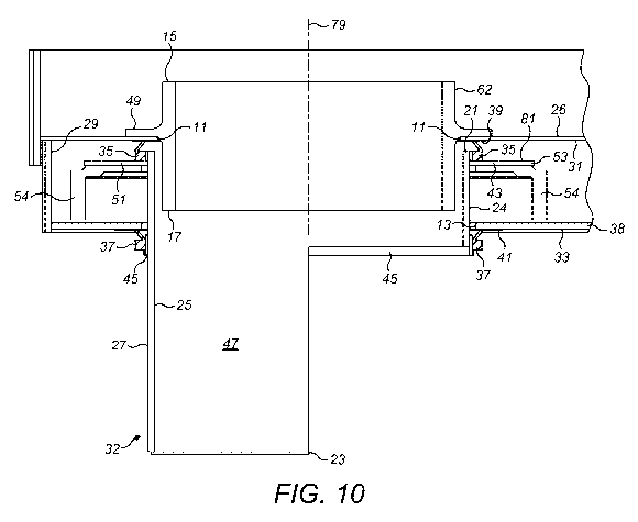
Referring to figures 10 and 11, according to the specific implementation,
sleeve 62
comprises a first upper cylindrical portion 62a and a second lower cylindrical
portion 62b
with portions 62a, 62b separated by a radially outward projecting annular
flange 49
configured to abut against a lower or base region of feedbox 26. The uppermost
region of
chute 32 (at the region of chute inlet 21) is positioned concentrically with
and surrounds
the sleeve axially lower portion 62b. Accordingly, an external facing surface
61 of sleeve
portion 62b is positioned opposed to an internal facing surface 25 of chute 32
that define
internal bore 47. Accordingly, sleeve outlet 17 extends into chute bore 47
beyond chute
inlet 21.
CA 03025027 2018-11-21
WO 2017/215734 PCT/EP2016/063581
-15-
Chute 32 comprises a radially outward projecting flange 43 extending from an
outward
facing surface 24 of chute 32 immediately below chute inlet 21. Flange 43 is
separated
from chute inlet 21 by a short axial distance. Flange 43 comprises a annular
downward
facing surface 51 configured for positioning against an annular upward facing
surface 53
.. of sheave structure 54. Accordingly, chute 32 is mounted to rest upon
sheave 54 and is
secured via fasteners 60 as illustrated referring to figure 5. First seal ring
35 is mounted to
extend around the uppermost end of chute 32 immediately below chute inlet 21.
In
particular, first seal ring 35 is configured to sit upon an upward facing
surface 81 of flange
43 and against chute outward facing surface 27. An upper portion of seal ring
35 is also
.. positioned opposed to a region of an inward facing surface 31 that defines
housing working
part zone 29. Seal ring 35 is positioned at housing internal facing surface 31
at a region
immediately surrounding first aperture 11. A thin plate-like annular gasket 39
is mounted
at housing inward facing surface 31 immediately around aperture 11 with first
seal ring 35
positioned against gasket 39. Seal ring 35 is secured so as to be rotatably
coupled to chute
32 via an annular clamp ring (not shown). Accordingly, seal ring 35 provides
an
appropriate seal between chute outward facing surface 27 and the housing
internal facing
surface 31 at the region of first aperture 11. Accordingly, a gap region
between chute inlet
21 and the working part zone 29 is sealed by seal ring 35 so as to prevent the
ingress of
dust and debris into the working part zone from the region of bore 47. In
particular, the
axial overlap of the sleeve lower portion 62b and the upper region of chute 32
is
configured to inhibit larger particulates from passing between the region of
the chute inlet
21 and housing 38, with finer entrained particles (dust) being blocked from
entering
working part zone 29 by the first seal ring 35.
The protection of the working part zone 29 and in particular the internal
drive components
described with reference to figures 3 to 6 (including in particular bearing
100 and
associated bearing surfaces) is enhanced by the provision of the second lower
seal ring 37.
Second seal ring 37 is a mirror image of first seal ring 35 and is mounted at
and in close
proximity to second aperture 13 so as to provide a dust seal arrangement at
the region
between chute external facing surface 27 and second aperture 13. According to
the
specific implementation, a second annular gasket 45 is mounted to extend
around chute
external facing surface 27 so as to provide a mount for second seal ring 37
which is
CA 03025027 2018-11-21
WO 2017/215734 PCT/EP2016/063581
-16-
similarly clamped onto chute 32 via a clamp ring (not shown). A third annular
plate-like
gasket 41 is mounted immediately around second aperture 13 at a region of an
external
facing surface 33 of housing 38. Accordingly, a part of second seal ring 37 is
mounted in
touching contact against third gasket 41 so as to provide an appropriate seal
between the
chute external facing surface 27 and second aperture 13.
According to the specific implementation, the first and second seal rings 35,
37 are
coaxially located at the external facing surface 27 of chute 32 and provide a
dual sealing
arrangement to prevent the ingress of dust into the working part zone 29 at
two separate
regions of housing 38 corresponding to the first and second apertures 11, 13.
As will be
appreciated, the first seal ring 35 is configured to prevent the ingress of
dust or particulates
flowing between the sleeve inlet 15 to chute outlet 23 whilst the second seal
ring 37 is
configured to prevent the ingress of dust into working part zone 29 resulting
from the
general dust laden environment immediately above the crusher and surrounding
the feet
distributor 18. As the chute 32 extends from an external region of the housing
38 (and the
working part zone 29) and into the housing 38 (and the working part zone 29),
the present
seal rings 35, 37 are positioned to seal against both the external and
internal facing surfaces
33, 31 of the housing to provide a secure seal to prevent dust ingress into
the working part
zone 29.
Referring to figures 12 and 13, each of the first and second seal rings 35, 37
comprises a
V-ring seal. In particular, each ring 35, 37 comprises an annular main body 65
having a
generally square cross sectional profile. A part conical flange 63 projects
upwardly from
main body 65 and is aligned transverse to central axis 79 about which each
ring 35, 37 is
centered. In particular, flange 63 of the first upper seal ring 35 is inclined
such that an
uppermost annular tip 71 of flange 63 is positioned closest to axis 79
relative to a base part
of flange 63 positioned at main body 65. Conversely, the corresponding flange
63 of
second seal ring 37 is declined such that the annular end tip 71 is positioned
radially
furthest from central axis 79 relative to a respective base part positioned at
main body 65.
Each seal ring main body 65 comprises an annular groove 67 formed in an
outward facing
surface of main body 65 to receive a clamp ring (not shown) so as to secure
each ring 35,
37 in position about the chute external facing surface 27. The use of V-ring
seals 35, 37 is
CA 03025027 2018-11-21
WO 2017/215734 PCT/EP2016/063581
-17-
advantageous in that flexible flanges 63 are configured to be urged against
the respective
sealing gaskets 39, 41 positioned at the respective regions of housing 38 (in
close
proximity to the first and second apertures 11, 13). Moreover, the flanges 63
are flexible
which is advantageous to reduce wear of the seal rings 35, 37 as they rotate
with chute 32
and against the respective gaskets 39, 41. Preferably, the material of each
seal ring 35, 37
comprises a polymeric material such as a polyurethane.
Referring to figure 14, the present feed distributor 18 is further
advantageous to reduce
dust ingress into the working part zone 29 by the creation and continuation of
a positive
pressure within the working part zone 29. Such a configuration is achieved via
the air feed
assembly 83 mounted at housing 38 and provided in fluid communication with the
working
part zone 29. According to the specific implementation, air feed assembly 83
comprises
ducting 73 mounted at housing external facing surface 33 via a mount boss 75.
A fan,
compressor or other pneumatic drive (not shown) of conventional design is
mounted within
or coupled to ducting 73 so as to force a flow of air through ducting 73 and
into the
working part zone 29 via an aperture (not shown) with a wall of housing 38
(defined
between the internal and external facing surfaces 31, 33). The air feed
assembly 38 is
compatible for use with a feed distributor 18 comprising first and second seal
rings 35, 37
and also with a corresponding distributor 18 that does not comprise respective
seal rings
35, 37. That is, where the distributor 18 comprises seal rings 35, 37, the
positive air
pressure created within working part zone 29 may be modest so as to provide a
modest
'back pressure' against the respective flanges 63 of the seal rings 35, 37.
The prevention
of dust ingress is accordingly provided by a combination of the positive air
pressure and
the seal rings 35, 37. Such an embodiment may involve providing a small (1 to
5 mm) gap
between the respective flanges 63 and the respective gaskets 39, 41 so as to
allow a low to
modest exhaust air flow to exit working part zone 29 at the two regions of the
housing
apertures 11, 13. As will be appreciated, such an exhaust air flow at the
region between
chute 32 and each respective housing aperture 11, 13 is effective to prevent
dust ingress
that would otherwise need to flow in the opposite flow direction, against the
exhaust air
flow. However, the combination of the air feed assembly 83 and seal rings 35,
37 is also
compatible with no gap between the respective seal rings 35, 37 and gaskets
39, 41. As
will be appreciated, appropriate control units may be coupled to the air flow
drive (fan,
CA 03025027 2018-11-21
WO 2017/215734
PCT/EP2016/063581
-18-
compressor etc.,) so as to regulate and control the magnitude of the positive
pressure
within the working part zone 29 and accordingly the flow speed of the exhaust
air stream
from housing apertures 11, 13.