Note: Descriptions are shown in the official language in which they were submitted.
CA 03025246 2018-11-22
WO 2017/125780 PCT/IB2016/001692
HEAT SHRINK COVERING OF BUILT STRUCTURES AND METHOD
(0001] The present invention relates to protective
covering of roofs and walls of built structures by polymer
sheeting and, more particularly, to the temporary covering
of damaged or under construction roofs, or as permanent
sarking under roof covering or wall cladding.
BACKGROUND
[0002] The use of polymer sheeting for the protection of
damaged roofs, or for weatherproofing buildings under
construction, is known and was described for example in
AU2009200232 and PCT/AU2009/000685 by the present inventor
and the text of which is largely incorporated in this
specification.
[0003] US6425213 (cited against an applicant's US
application 12/995966) also describes a system of wrapping
a building in a water impermeable layer but relies on the
application of successive overlapping strips which are not
secured one to another and would be liable to dislodgement
in high wind conditions, and moreover is not for the repair
of damaged roofs but as proofing against flooding.
[0004] Roofs are of course susceptible to damage from
high winds, rain or hail. Tiled roofs for example may have
a considerable area of tiles either damaged from hail
impact, or dislodged completely as the result of high
CA 03025246 2018-11-22
WO 2017/125780 PCT/IB2016/001692
2
intensity storms. Shingled roofs are liable to be similarly
damaged, and even metal sheeted roofs may suffer partial or
total removal of one or more sheets. Damage to roofs may
also be caused by the impact of falling trees, large
branches, or other objects made airborne under high wind
conditions.
[0005] Storm or impact damage cannot usually be
immediately repaired so that to prevent further or
potential damage to the interior of the building, temporary
W covering must be provided. Typically canvas (or similar
material) tarpaulins are placed over the damaged part of
the roof and secured to the structure by ropes.
[0006] One disadvantage of this method of temporary
covering is the difficulty of adequately securing a
tarpaulin to the roof so that they remain very vulnerable
to dislodgement should high winds prevail or recur and
often require continuing attention and adjustment.
Moreover, they are heavy and awkward to position, posing
occupational health and safety issues. A further
disadvantage is that they are expensive to acquire and
bulky to store, and if the many roofs are damaged in one
storm event, the number of tarpaulins available may be
inadequate.
[0007] Buildings under construction, particularly timber
framed, brick clad dwellings, are frequently constructed in
a sequence where the timber frame, including that of the
CA 03025246 2018-11-22
WO 2017/125780 PCT/IB2016/001692
3
roof, is completed a considerable time before the roof
cladding can be added. A disadvantage of this construction
technique is that during this period the timber of the
structure, which may even include timber or particle board
flooring, is liable to deterioration from water and sun. A
further disadvantage of this sequence of construction is
that, if rain intervenes at the time further internal work
is scheduled, the lack of roof covering may cause
considerable delay and financial loss.
W [0008] A system of covering a roof with a film of
material for the purpose of preventing damage from wind
shear was disclosed in US 2005/0217202, although again this
is therefore not directed at the covering after storm
damage. Moreover this US application teaches a method of
application of the film from a roll of film hoisted up onto
the roof surface, the film being unrolled in situ with
overlapping edges of the film being secured by the
application of adhesive tape. Rolls of film are heavy and
in practice the manipulation of a roll of film and the edge
taping required on even an intact roof surface is extremely
difficult, if not dangerous and is completely impractical
for application to the roof framing of an uncompleted
building.
[0009] It is known for both damaged roofs and
uncompleted framed roofs, to prepare sufficiently assembled
strips of film at ground level for subsequent application
CA 03025246 2018-11-22
WO 2017/125780 PCT/IB2016/001692
4
to the roof, as disclosed in the present applicant's patent
AU2008203409. In practice however, it has been found that
the sealing of an extensively damaged roof, or the covering
of a roof still under construction by a continuous sheet of
film material, can lead to unacceptable stress at the seams
and attached edges of the sheet. This stress is due to wind
action both passing over the sheet surface, and acting on
the sheet from below,
[00010] A further problem, not previously addressed, is
that even at ground level, the assembly of a number or
adjoining sheets of polymer film into a sheet large enough
to cover a roof, especially in the case of storm damage,
wind conditions make the control of adjoining sheets
extremely difficult. US4672941 discloses a system for
assembling by welding horizontally overlapping sheets of
therMoplastic, but this involves a large, cumbersome
wheeled machine which travels over the sheets. Another
overlap welding arrangement is disclosed in US3257257 which
again involves the use of a welding machine travelling
along the overlap between adjacent sheets. Apart from the
relatively complicated machine, the system relies on a
well-defined trench built into a supporting surface for
accommodating a conveyor belt system and is thus completely
unsuited to on site use.
[00011] There is thus a need for simple, readily portable
but efficient equipment to control overlapping sheets laid
CA 03025246 2018-11-22
WO 2017/125780 PCT/IB2016/001692
out on a ground surface at the site of application. In
particular, for heat welding to provided consistent and
strong joints, that simple equipment must provide for a
controlled application of heat to the overlap portions of
5 adjoining sheets applied at a predetermined rate.
[00012] It is an object of the present invention to
address or at least ameliorate some of the above
disadvantages.
Notes
[00013] The term 'comprising" (and grammatical variations
thereof) is used in this specification in the inclusive
sense of "having" or "including", and not in the exclusive
sense of "consisting only of".
[00014] The above discussion of the prior art in the
Background of the invention, is not an admission that any
information discussed therein is citable prior art or part
of the Common general knowledge of persons skilled in the
art in any country.
BRIEF DESCRIPTION OF INVENTION
[00015] Accordingly, in a first broad form of the
invention, there is provided a system for providing covers
for surface areas of built structures; the system including
a film of heat shrinkable material for stretching and heat
shrinking over one or more of the surfaces of the built
structure; the film formed as a sheet comprising an
CA 03025246 2018-11-22
WO 2017/125780 PCT/IB2016/001692
6
assembly of lengths of the heat shrinkable material
prepared on a supporting surface; characterized in that the
sheet is prepared by applying heat to overlap portions
between adjoining lengths of the heat shrinkable material
while the overlap portions are secured in contact between
the supporting surface and a guide rail assembly laid over
the overlap portions; the overlap portions welded together
by a heat gun moveable along the guide rail assembly at a
predetermined distance above the overlap portions.
W [00016] Preferably, the supporting surface is a ground
surface.
[00017] Preferably, the supporting surface is a surface
of a supporting element placed on a ground surface.
[00018] Preferably, the guide rail assembly comprises
Is spaced apart guide rail elements interconnected at their
outer ends by connecting elements.
[00019] Preferably, the guide rail elements are provided
with inward facing recesses.
[00020] Preferably, spacing between the guide rail
20 elements is in the range of 15 to 30mm.
[00021] Preferably, the supporting element comprises a
length of heat resistant material.
[00022] Preferably, the supporting element is provided
with a length of rope or cable attached to one end of the
25 supporting element; the length, of rope or cable being at
CA 03025246 2018-11-22
WO 2017/125780 PCT/IB2016/001692
7
least the length of a length of overlap of two adjoining
lengths of the heat shrinkable material.
[00023] Preferably, a heat gun is provided with a heat
directing shroud; width of the heat directing shroud sized
so as to fit between edges of the recesses provided in the
guide rail elements of the guide rail assembly.
[00024] Preferably, a length of the heat directing shroud
is sized to provide fusion of a portion of the overlap of
the two adjoining lengths of heat shrinkable material in a
predetermined time.
[00025] Preferably, consistency and quality of a weld is
ensured by separation between the heat gun and the overlap
of material and a predefined rate of travel of the heat gun
along the guide rail.
0 [00026] Preferably, undersides of the rail elements of
the guide rail assembly are provided with strips of a heat
insulating material,
[00027] Preferably, at least one air vent is provided in
any of the lengths of heat shrinkable material; the air
vent comprising an aperture and an overlying cover.
[00028] Preferably, three sides of material comprising
the overlying cover overlap three edges of the aperture and
are welded to the surface of the length of heat shrinkable
material; a fourth side of the overlying cover overlapping
a fourth edge of the aperture by at least 300mm.
CA 03025246 2018-11-22
WO 2017/125780 PCT/IB2016/001692
8
[00029] In another broad form of the invention, there is
provided a method of preparing a film of material for
covering surfaces of a built structure; the film comprising
an assembly of lengths of heat shrinkable material; the
method including the step of aplying heat along an overlap
between adjoining lengths of the heat shrinkable material;
characterized in that the application of heat is guided by
a guide rail assembly; the guide rail assembly placed over
a section of overlap lying on an elongate supporting
element positioned on a ground surface.
(000301 Preferably, the method includes the steps of:
1) positioning the elongate supporting element on a
ground surface.
2) extending a rope or cable attached at an end of the
supporting element along an intended position of an
overlap of two adjoining lengths of the heat
shrinkable material,
3) positioning the two adjoining lengths of the heat
shrinkable material with a predetermined overlap
over the supporting element and the rope or cable,
4) positioning the guide rail assembly over a first
overlap portion of the two adjoining lengths of the
heat shrinkable material and coincident with the
supporting element,
5) moving a heat gun provided with a heat directing
shroud along the guide rail assembly to fuse the
CA 03025246 2018-11-22
WO 2017/125780 PCT/IB2016/001692
9
first overlap portion of the two lengths of heat
shrinkable material together.
[00031] Preferably, subsequent overlap portions of the
two adjoining lengths of heat shrinkable material are fused
together by the steps of:
6) removing the guide rail assembly from the first or
preceding overlap portion,
7) using the rope or cable to reposition the
supporting element under a next overlap portion of
JO the adjoining lengths of the heat shrinkable
material,
8) positioning the guide rail assembly over the next
overlap portion and coincident with the supporting
element,
= 9) moving the heat gun provided with the heat
directing shroud along the guide rail assembly to
fuse the next overlap portion of the two lengths of
heat shrinkable material together.
[00032]
Preferably, the guide rail assembly comprises two
spaced apart guide rail elements interconnected at their
outer ends by connector elements.
[00033]
Preferably, at least one air vent is provided in
at least one length of the heat shrinkable material; the
air vent comprising a pre-cut aperture in the length of
heat shrinkable material and a cover; three sides of the
cover overlapping three edges of the aperture and welded to
CA 03025246 2018-11-22
WO 2017/125780 PCT/IB2016/001692
the length of heat shrinkable material; a fourth side of
the cover over lapping a fourth edge of the aperture by at
least 300mm.
[00034] In a further
broad form of the invention, there
5 is provided a method of preparing an assembly of sheets of
a heat shrinkable material on a ground surface; the
assembly of sheets prepared for covering one or more
surfaces of a built structure; the method including
locating overlapping lengths of adjacent strips of the heat
10 shrinkable material between a supporting surface and a
guide rail assembly placed over the overlapping lengths; a
heat source movable along the guide rail assembly at a
predetermined rate heat welding the overlapping lengths to
form the assembly of sheets.
[00035] Preferably, the heat
source is a heat gun mounted
on a trolley adapted for movement along rails comprising
the guide rail assembly.
[00036] Preferably, the trolley is powered to give a
controlled rate of movement along the rail system.
[00037] In another broad
form of the invention, there is
provided a method of covering a storm damaged area of a
roof of a built structure; the method includes the step of
preparing an assembly of sheets of a heat shrinkable
material on a ground surface; the method including
sequentially applying the steps of:
CA 03025246 2018-11-22
WO 2017/125780 PCT/1112016/001692
11
1) arranging a two adjoining sheets of the heat
shrinkable material with an overlap over a supporting
surface;
2) securing the first portion of the overlap by placing a
guide rails assembly over the first portion of the
overlap,
3) applying heat to the first portion of the overlap by
moving a heat source along the guide rail assembly to
weld overlap portions of the sheets along the first
overlap portion together,
4) sequentially moving the guide rail assembly to
subsequent portions of the overlap to weld subsequent
overlap portions together to a required length of the
assembly of sheets of heat shrinkable material.
[00038]
Preferably, the method includes the further steps
of:
1) pulling the assembly of sheets onto the roof surface
to cover at least the storm damaged area of the roof,
2) attaching at least opposing edges of the assembly of
sheets to battens,
3) securing the battens at the opposing edges of the
assembly of sheets to any one of eaves, facia boards
or roof battens.
[00039] Preferably, the guide element is a guide rail
assembly; the guide rail assembly structured to constrain
CA 03025246 2018-11-22
WO 2017/125780 PCT/IB2016/001692
12
movement of the heat source along the portion of the
overlap at a predetermined separation above the heat
shrinkable material.
[00040] In another broad form of the invention, there is
provided a method of preparing a sarking layer for a built
structure; the sarking layer comprising an assembly of
sheets of a heat shrinkable material; the method including
the steps of:
1) positioning a portion of an overlap between two
adjoining sheets of the heat shrinkable material on a
supporting surface,
2)positioning a guide rail assembly over a first portion
of the overlap to secure the first portion of the
overlap between the supporting surface and the guide
rail assembly,
3)moving a heat source along the guide rail assembly to
heat weld the overlap portions of the adjoining sheets
of heat shrinkable material one to another,
4)moving the guide rail assembly to a next overlapping
portion of the adjoining sheets of heat shrinkable
material and repeating step 3 until a required length
of the assembly of sheets of heat shrinkable material
is reached,
5) adding a further adjoining sheet of heat shrinkable
material to form a further overlap portion and
repeating steps 1 to 4 until a required width of the
CA 03025246 2018-11-22
WO 2017/125780 PCT/IB2016/001692
13
assembly of sheets of heat shrinkable material is
reached.
100041]
In still a further broad form of the invention,
there is provided a method of temporarily waterproofing a
storm damaged area of a roof of a built structure by
securing an assembly of sheets of heat shrinkable material
to at least a portion of the roof surface; the assembly of
sheets prepared by heat welding overlap portions of
adjoining sheets; the method including the steps of
W securing sequential overlap portions of the adjoining
sheets between a supporting surface and a guide rail
assembly, and passing a heat source along the guide rail
assembly.
[00042]
Preferably, the method includes the further steps
of:
1)pulling the assembly of sheets of heat shrinkable
material onto the roof surface to cover the storm
damaged area,
2) securing battens to at least two opposing edges of
the assembly of sheets of the heat shrinkable
material,
3) securing the battens to eaves, facia boards or roof
battens,
4) applying the heat source to the heat shrinkable
= 25 material Co tightly conform the assembly of sheets to
the roof surface.
CA 03025246 2018-11-22
WO 2017/125780 PCT/IB2016/001692
14
[00043] In
still a further broad form of the invention,
there is provided a method of preparing and securing an
assembly of sheets of heat shrinkable material over a
damaged section of a roof surface; the method including the
steps of:
1) drawing and cutting from a roll of the heat shrinkable
material a required number of sheets at a required
length to cover the damaged section,
2) arranging on a supporting surface adjoining lengths of
the heat shrinkable material with a predetermined
overlap,
3)placing a guide rail assembly over a first portion of
the overlap to secure the first portion of the overlap
between the supporting surface and the guide rail
assembly,
4)moving a heat source along the guide rail assembly to
weld respective overlap portions of the adjoining
sheets one to the other,
5)moving the guide rail assembly to any required
subsequent portions of the overlap and repeating step
4 to complete welding of the overlap,
6) adding as required further lengths of the heat
shrinkable material and repeating steps 2 to 5 to
complete the assembly of sheets,
CA 03025246 2018-11-22
WO 2017/125780 PCT/IB2016/001692
7) pulling the assembly of sheets with the battens onto
the roof surface to cover the damaged section of the
roof surface,
8) affixing battens to at least two opposing edges of the
5 assembly of sheets,
9) affixing the battens at the two opposing edges of the
assembly of sheets to suitable elements of the roof,
10) applying the heat source to the surface of the
assembly of sheets to tighten the heat shrinkable
10 material into conformity with the roof surface.
100044] Preferably, the supporting surface is a ground
surface.
[00045] Preferably, the supporting surface is the upper
surface a length of heat resistant material substantially
15 coextensive with the guide rail assembly.
[00046] .. Preferably, the length of heat resistant material
is pulled from the first portion of the overlap to
subsequent portions of the overlap by a rope or cable
extending from the length of heat resistant material.
[00047] In another broad form of the invention, there is
provided a kit for temporary repair of a storm damaged roof
or other surface of a built structure; the kit comprising a
box enclosing at least one roll of heat shrinkable
material, a heat source and a guide rail assembly.
[00048] Preferably, the roll or rolls of heat shrinkable
material are rotatably mounted within the box enabling
CA 03025246 2018-11-22
WO 2017/125780 PCT/IB2016/001692
16
lengths of the heat shrinkable material to be drawn from
the box for use.
[00049] The kit of claim 33 or 34 wherein the heat
shrinkable material is wound onto the roll or rolls in a
twice folded state; the width of the heat shrinkable
material when spread out after cutting from a roll
approximately equal to three times the width of the roll.
[00050] Preferably, adjacent 'lengths of the heat
shrinkable material are spread on a supporting surface with
W a predetermined overlap of one length of the heat
shrinkable material over the other; the guide rail assembly
positioned over a first overlap portion of the overlap and
the heat source moved along the guide rail assembly to weld
the adjoining lengths along the first overlap portion.
BRIEF DESCRIPTION OF DRAWINGS
[00051] Embodiments of the present invention will now be
described with reference to the accompanying drawings
wherein:
Figure 1 is a perspective view of a portion of a
building of which the roof has sustained damage,
Figure 2 is a side sectioned view of a portion of a
building and existing roof structure to which has been
applied a roof cover system according to the invention,
CA 03025246 2018-11-22
WO 2017/125780 PCT/IB2016/001692
17
Figure 3 is a side sectioned view of a portion of a
partly completed building showing the application of a roof
cover system of the invention to unclad roof framing,
Figure 4 is a further side sectioned view of the
building of Figure 3 showing the roof cover system of the
invention functioning as a permanent sarking layer,
Figure 5 is an illustration of the preparation of a
sheet of heat shrinkable material prepared on a ground
surface as an assembly of lengths of material taken from a
roll of film,
Figure 6 is a perspective view of a portion of heat
shrinkable material in position over a section of roof in
which the sheets of material were prior prepared with air
vents,
Figure 6a is a perspective view of one preferred
embodiment of the air vents of Figure 6,
Figure 7 is a perspective view of a supporting element
laid out on a ground surface in preparation of assembly of
lengths of material according to a fourth embodiment of the
invention,
Figure 8 shows portions of two adjoining, overlapped
lengths of material laid out so that a first portion of the
overlap lies over the supporting element of Figure 7,
Figure 9 is a perspective view of a guide rail
assembly for use with the supporting element of figure 7,
CA 03025246 2018-11-22
WO 2017/125780 PCT/IB2016/001692
18
Figure 10 is a cross section of the guide rail
assembly of figure 9 showing a portion of a heat gun and
the overlap of the two length of material supported on the
supporting element of figure 7,
Figure 11 is a further cross section view of a roof of
a building showing an alternative method of securing a roof
cover according to the invention to the roof,
Figure 12 is a view of a preferred arrangement of
folding the heat shrinkable material for winding onto a
dispensing roll rotationally supported in kit box,
Figure 13 is an extract from a laboratory test report
on performance characteristics of the heat shrinkable
material,
Figures 14 and 15 illustrate the use of an assembly of
sheets of shrinkable material prepared according to the
invention for application to the roof and wall structures
of a building as a sarking layer.
DETAILED DESCRIPTION OF PREFERRED EMBODIMENTS
[000521 The roof
cover system of the present invention
provides for a system and method for covering a damaged or
uncompleted roof of a building. The system uses a heat
shrinkable film, preferably a low-density polyethylene
containing shrinking resins, UV inhibitors, anti brittling
compounds, fire retardant additives and strengtheners for
tear resistance. The film is preferably between 100 and
CA 03025246 2018-11-22
WO 2017/125780 PCT/IB2016/001692
19
500m1crons in thickness, though most preferably 200microns,
and is provided in rolls of various widths and lengths. In
at least one preferred form of the film, it is provided
with a heat reflective surface. A preferred specification
for the film is given at the end of the description.
First Preferred Embodiment
[00053] With reference
now to Figure 1, typical
damage to a tiled roof 10 of a building 12 may include the
loss of a number of tiles 12 due to a high wind shear
event, leaving the building 14 open to the ingress of
water. Water ingress may also occur if tiles are cracked
for example from heavy hail impact or falling trees or
branches. Emergency temporary repair is provided by the
roof cover system of the invention by applying the above
described film over that portion of the roof which has
sustained damage.
[00054] If required,
sharp edges protruding from the roof
surface may first be covered with suitable wadding and
adhesive tape to prevent possible tearing of the film
during application.
[00055] The extent of
roof to be covered is measured and
the most suitable available width roll of the heat
shrinkable film selected. Film is cut to one or more
lengths sufficient to extend from one edge of the roof to
an opposite edge. With reference to Figure 2, a trailing
CA 03025246 2018-11-22
WO 2017/125780 PCT/IB2016/001692
edge of a length of film is mechanically attached at the
first edge 16 of the roof 10. In one preferred method as
shown in Figure 2, the trailing edge 15 of the film 18 is
wrapped once around a length of batten 18, preferably as
5 long as the width of the film, and the batten 20
mechanically fixed to the underside 22 of the eaves 24 at
the first edge of the roof 10. In still another possible
arrangement, the batten 20 can be fixed directly to an
existing batten through the roof tiles, as shown in Figure
10 11.
[00056] The leading edge is now passed over the roof to
the opposite edge (not shown) of the roof and the leading
edge secured to the opposite side eaves in similar manner
to that already described. If the outer side edge of the
15 length of film adjoins an edge of the roof, this may be
similarly secured under the eaves along that side of the
roof. Alternatively, the leading edge may =be secured to the
barge or fascia boards.
[00057] Heat is now applied to the film at the underside
20 of the eaves 24 with a heat gun (not shown) to cause the
film 18 to shrink securely around the batten and the
undersides of the eaves. The heat gun, now attached to an
extension arm (not shown), is then used to apply heat to at
least a region around the perimeter of the film 18
stretched over the roof surface, causing it to tightly
CA 03025246 2018-11-22
WO 2017/125780 PCT/IB2016/001692
21
conform to the surface and covering missing or cracked
tiles 12.
1000561 If the extent of the damage requires, successive
lengths of film can be applied side by side with an overlap
of preferably 150 to ro300mm. Heat is applied along these
overlaps to seal the edges of the adjoining lengths
together.
[000591 Valley areas and other discontinuities in the
roof surface can be accommodated by cutting film to suit
the area involved and heat sealing to adjoining film length
edges. Vertical roof penetrations, such as chimney stacks
ventilators and the like, are sealed by preferably a 300mm
rise of film. Edges of riser sections of film can be taped
or cable-tied to the penetration.
[000601 By the above means, a damaged roof can be rapidly
and securely covered to prevent water ingress and damage to
the inside of the building. Unlike tarpaulins which are
difficult to secure and remain liable to dislodgement in
high winds, the heat shrinkable film by conforming closely
to the roof surface, provides a secure seal over the damage
until permanent repairs can be made.
Second Preferred Embodiment
[00061] In a second preferred embodiment of the
invention, a damaged section of a roof to be temporarily
protected prior to permanent repair, is again covered by a
CA 03025246 2018-11-22
WO 2017/125780 PCT/IB2016/001692
22
heat shrinkable film, In this embodiment however, the
method of application is different.
t00062]
Instead of attempting to apply individual lengths
of film, attaching a length at a first end to the eaves at
one side of the roof, stretching the length over the roof
to be attached at the eaves at the opposite side, and
taping the edges of adjoining lengths of film together, the
method of this embodiment, with reference to Figure 5 is as
follows:
(a) the location of the damaged section 12 of roof 10
is assessed in relation to the nearest opposing
edges of the roof,
(b) the length of film required to extend between the
opposing roof edges is estimated, allowing for
overhang and fixing requirements,
(c) the width of the damaged area is ascertained and
the number of lengths of the available film
required to cover and overlap the damaged area
determined,
(d) the number of lengths of material 18 is then cut
from a roll 40 of the film and laid out side by
side on the ground,
(e) while on the ground, adjoining edges of the
lengths of film are taped to form a waterproof
assembled sheet of heat shrinkable film, sufficient
to stretch from one roof edge to the opposite roof
CA 03025246 2018-11-22
WO 2017/125780 PCT/IB2016/001692
23
edges and of sufficient width to cover the damaged
area.
[00063] This assembled sheet is now pulled up onto the
roof, positioned so as to cover the damaged area and outer
ends fastened in similar manner as previously described
above.
[00064] An advantage of this method is that there is no
need to lift a relatively heavy roll of heat shrinkable
material onto the roof and unroll it one what may be quite
steep surfaces. Moreover it has been found in practice that
the arrangement described in the first preferred embodiment
above of taping the edges of adjoining lengths of the
material together on the roof is both difficult and
dangerous. This is especially so if the damage to the roof
is extensive and perhaps been rendered structurally unsafe.
The method of the present described embodiment minimises
activity on the roof surface, requiring only that one edge
of the sheet of material be carried over the roof from a
first edge to an opposite edge.
Third Preferred Embodiment
[00065] In a third preferred embodiment of the invention,
a heat shrinkable film may be applied to the roof framing
of an uncompleted building. In this embodiment as shown in
Figure 3, the heat shrinkable film 18 is applied after the
CA 03025246 2018-11-22
WO 2017/125780 PCT/IB2016/001692
24
roof framing is complete but preferably prior to the
attachment of facia boards.
[00066] In this embodiment also, lengths of film are
prepared from suitable width rolls sufficient to stretch
from one side of the roof to an opposite side. In this case
the trailing and leading edges of the length of film are
preferably attached by means of battens 20 fixed to the
underside of the outer ends 26 of rafters 28, that is
between the outer ends of the rafters 28 and the wall frame
30.
[00067] The heat shrinkable film 18 in this embodiment,
is provided with a heat reflecting inner surface 32 so that
the film 18 forms a permanent sarking layer behind the wall
cladding or under the roof cladding, either tiles 34, as
shown in Figure 4, or metal sheeting. Thus in this
embodiment the heat shrinkable film of the invention act
both to protect the timberwork of a building under
construction and provides a replacement for conventional
reflective sarking.
[00066] The weatherproof nature of the heat shrinkable
material applied in this way provides for internal work on
the building to continue in the event of inclement weather,
thus increasing productivity and economy of construction.
[00069] It will be understood that the method of
application described in the second preferred embodiment
above is also, indeed perhaps even more so, applicable to
CA 03025246 2018-11-22
WO 2017/125780 PCT/IB2016/001692
the present embodiment. In this case manipulating a roll of
material and taping edges of lengths of material together
over the open framework of the roof of a building under
construction is even more difficult so that assembly on the
5 ground, perhaps into a number of sheets, prior to placement
over the roof framing, is clearly advantageous.
[00070] In each of the above described embodiments, the
sheet of material may be further prepared, as shown in
Figure 6, by adding a distribution of air vents 100 at
10 various locations in each of the strips 18. Preferably, the
vents 100, as shown in Figures 6 and 6A, take the form of
one-way covers or flaps 110 which are affixed over an
aperture 112 cut into the strips of film 18 at the desired
location. The flaps 110 are so arranged as to prevent the
15 ingress of rainwater while allowing the passage of air.
[00071] In one preferred form the vent 100 is pre-formed
of low density polyethylene and provided with a self
adhesive base 114, To apply the vent 100 after the aperture
has been prepared, a protective cover 116 is peeled off the
20 adhesive layer of base 114 and the vent 100 pressed into
position.
[00072] These vents allow the exhalation of air from
underneath the sheet of material, either as a result of
higher air pressure arising within the roof space, for
25 example through rising warm air or through the ingress of
wind, or due to negative pressure above the sheet material.
CA 03025246 2018-11-22
W02017/125780 PCT/IB2016/001692
26
Fourth. Preferred Embodiment
[00073] In the above described embodiments, in those
cases where two or more adjoining lengths of heat
shrinkable material were described as assembled into a
sheet on a ground surface, the lengths of material were
secured together by adhesive tape. While this can be
adequate for temporary cover of a storm damaged structure
for example, a stronger and, where required, a far stronger
and more permanent solution is the heat welding of
adjoining lengths of material along an overlap.
[00074] Nevertheless, prior to welding, it is preferable
to hold the edge of the uppermost sheet of the overlap in
place by adhesive tape to prevent problems in windy
conditions.
[00075] With reference now to figures 7 to 10, in the
present invention, in one preferred arrangement an elongate
support element 200 is laid at a convenient location on the
ground surface on which the sheet is to be assembled, The
support element 200 may comprise a length of timber or
other, substantially heat resistant material, preferably
200mm wide and somewhat longer than the length of weld in a
weld sequence. The support element is provided with an
attached rope or cable 210 of sufficient length to extend
the length of the lengths of heat shrinkable material to be
joined together. This rope or cable 210 is stretched out in
CA 03025246 2018-11-22
WO 2017/125780 PCT/IB2016/001692
27
line with the support element 200 and along the intended
join between two lengths of the material.
[00076] As shown in Figure 8, two adjoining lengths of
heat shrinkable material 212 and 214 are then laid out side
by side with an overlap 216 of approximately 150mm over the
supporting element 200 and the rope or cable 210, and so
that the supporting element 200 underlies a first portion
218 of the overlap. Adhesive tape is applied to the outer
edge of the overlap, at least for the first portion 218 of
the overlap 216, if required.
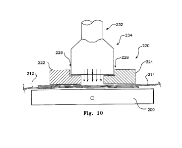
[00077] As shown in Figure 10, a guide rail assembly 220
substantially coextensive with the supporting element, is
then laid over and centrally along the first portion 216 of
the overlap, with the guide rail assembly resting on the
supporting element 200 so that the overlapping portions of
the two lengths of material 212 and 214 are secured between
the guide rail assembly 220 and the supporting element 200.
[00078] The guide rail assembly 220 comprises two, spaced
apart, rigid rail elements 222 and 224, preferably lm in
length but may be provided in various lengths, for example
300, 600 or 1200mm. The rail elements 222 and 224 are
interconnected at their outer ends by connection cross
members 226 and 228. Preferably, the end profiles of the
rail elements 222 and 224 are as shown in Figure 10 with
recessed inward facing edges 225 and 227 and are preferably
spaced 20mm apart. The recesses are so arranged to guide a
CA 03025246 2018-11-22
WO 2017/125780 PCT/IB2016/001692
28
heat source at a predetermined distance above the overlap.
The rail elements 222 and 224 are formed of metal, steel or
preferably aluminium. Finally, the rail assembly 220 is
provided with at least one, preferably two grab handles 230
for manipulating the assembly in use.
[00079] A heat gun 232 (partly shown in Figure 10) is
provided with a heat directing shroud 234 sized in width to
fit between the recessed edges 226 and 228 of the guide
rail assembly 220 and a length sized to deliver a quantum
of heat to an area of overlapping sheets of material
between the rail assembly, sufficient to fuse that area
together within a predetermined time duration.
[00080] The heat gun 232 with its attached shroud 234 in
drawn along the guide rail assembly 220 at an even rate,
thus fusing that length of overlap 216 covered by the rail
assembly. In one preferred arrangement, the heat gun may be
mounted on a trolley (not shown) which traverses the guide
rail. The heat gun may be moved along the guide rail
manually, or the trolley could be powered to give a
controlled rate of movement.
[00081] The arrangement of the guide rail which controls
the separation of the heat gun from the material, combined
with a predefined rate of travel, assures the consistency
and quality of the weld.
[00082] The supporting element 200 is then drawn with the
rope or cable 210 into a next position along the sheet
CA 03025246 2018-11-22
WO 2017/125780 PCT/182016/001692
29
overlap and the guide rail assembly 220 repositioned
accordingly. Heat is then applied to this next length of
the overlap, and the process repeated until the required
length of sheet assembly is reached.
[00083J In an alternative arrangement, the sheets of
material may be laid out over a suitable ground surface
such as for example a nearby car park or a suitably flat
area of lawn. In this instance, the overlap portion is
again secured prior to the welding process by the placement
of the guide rail assembly over the overlap portion and the
heat source applied as described above. After welding this
first overlap portion, the guide rail assembly is
positioned over a next overlap potion until a required
length of sheet assembly is reached.
t00084] The air vents 100 referred to above and shown in
Figure 5, may be welded into the required locations in
similar fashion. The cover piece of material forming the
vent cover preferably overlaps three of the sides of the
pre-cut aperture in the sheet of material sufficient for
welding the overlap as described for the joining of the two
lengths of material. These three sides of the piece of
material forming the vent cover are welded to the length of
material around the pre-cut aperture, with the fourth side
of the material arranged to overlap the aperture by a
minimum of 300mm.
CA 03025246 2018-11-22
WO 2017/125780 PCT/IB2016/001692
OOHS] The arrangement of this preferred embodiment
allows for very secure, watertight and relatively accurate
joining of adjoining lengths of the heat shrinkable
material, The portion of overlap to be joined is held
5 securely by the weight of the guide rail assembly while the
guide rail profiles both a guide and control of the
application of fusing heat.
[00086] The assembly of sheets is prepared for fastening
to the roof by adding securing battens at least along two
10 opposing edges after pulling the assembly up onto the roof
surface to cover the damaged areas. The battens are then
mechanically secured either to the eaves of the roof, the
facia boards or, if the damage is restricted to a
relatively small area of the roof, to battens of the roof
15 structure.
[00087] In this latter case and for a tiled roof as shown
in Figure 11, a masonry drill bit is used to drill holes
through tiles coincident with the underlying roof batten
and fasteners driven through the securing batten, the tiles
20 and into the roof batten. Once in position, the heat source
is applied to the assembly of sheets to tighten the heat
shrinkable material into conformity with the roof surface.
[00088] The heat shrinkable material, guide rail
assembly, heat gun, tape and associated tools may be
25 provided in kit form. In a preferred arrangement shown in
Figure 12, a box 40 is provided in which at least one,
CA 03025246 2018-11-22
WO 2017/125780 PCT/IB2016/001692
31
preferably two rolls 42, of the heat shrinkable material 44
are rotationally supported so as to allow the material to
be drawn from the box. The box 40 is provided with a stop
46 which allows the lid 48 to be propped open leaving a
narrow slit for the material 44 to be drawn through while
at the same time providing a cutting guide for cutting the
material when drawn out to a required length. The box is
further provided with a compartment 50 for storage of the
heat source and ancillary equipment (not shown).
100089] Preferably, the heat shrinkable material is wound
onto the rolls 40 folded as shown in Figure 12 so that when
drawn from the box and opened out the sheet of material is
approximately four times the width of the roll from which
is was drawn.
[00090] It will be understood that the procedure of the
assembly of lengths of the heat shrinkable material as
described for this embodiment may equally be applied for
the assembly of sheets of heat shrinkable material intended
to form a sarking layer for the roof or walls of a building
where the sarking layer is secured to the roof and wall
framing before applying the roof and wall cladding.
In Use
[00091] In use, one or more kits are transported to a
site where damage to a roof has occurred. The damaged area
25= is measured and the number of lengths to cover the width
and the length of the lengths of material determined. These
CA 03025246 2018-11-22
WO 2017/125780 PCT/IB2016/001692
32
lengths are drawn from the kit box and an initial two
lengths placed side by side on the supporting surface,
which may be directly on the ground or on a supporting
element, with the required overlap, and the overlap welded
as described above.
[00092] The welding
process described in this embodiment
of the invention has been proven to provide extremely
strong welds, well able to withstand any conceivable wind
load when applied to a roof or to the structure of a
building under construction, as attested by the extract
from a laboratory test report shown in Figure 13. As well,
wind tunnel testing has shown the welding process of the
invention will withstand wind speeds of up to at least
160Km/Hr.
Preferred Material Specification
[00093] A
blend of LDPE resin & LLDPE resin (suitable
resin examples Dowlex 2645 liner low density polyethylene
(LLDPE) with a relative density of 0.918 & melt index of
0.85 mixed with Dow 303E low density polyethylene (LDPE)
with a relative density 0.922 & melt index of 0.30. Best
performance is a mixture of 65% LDPE & 35% LLDPE.
UV screen additive minimum 1 year
Non halogen Fire retardant additive (high quality that can
be used on food grade manufacturing machines) Fire additive
to meet the French 41 standard
CA 03025246 2018-11-22
WO 2017/125780 PCT/IB2016/001692
33
200 micron in thickness (6 mil)
Roll length 131 ft (40m)
Roll "lay-flat" width 16.4 feet (5m) - Note roll to be
concertina folded to an overall width of 1300mm.
Film rolled onto heavy duty 3'inch (76mm) cardboard cores.
Each roll to weigh 83.67 pound (37.5 kg)
Stormseal logo to be printed on the film logo size - 3 ft
wide (1000mm) x 10 inches high (250mm) printed in a repeat
manner.
Film to have a minimum 40% shrink capability
High edge tear resistance
Minimum ultimate tensile strength 1000 pound per yard
(450kg per meter)
Application as Wall Saucing
= Select the correct width roll as it is important to
have the least amount of welds in the sealing process.
= Site measure the area which to be sealed.
= Ensure any sharp object are padded.
= Attach one side of the shrink wrap to the inside edge
of perimeter stud work. Securely fix by a continuous
batten.
= Take the leading edge of the said film across to the
Opposite the structure.
= Securely fix off the opposite side by continuous
batten.
CA 03025246 2018-11-22
WO 2017/125780 PCT/IB2016/001692
34
= Apply heat to the film wrapped stud in a continuous
even pattern with a similar motion of a spray paint
gun.
= Allow time for the film to shrink on to itself.
= Repeat this process to all vertical wall surfaces.
= Now using the heat gun extension tool apply an even
continuous heat to the entirety of the vertical wall
surface allowing enough passes for the shrink wrap to
contract.
= Continue this process with overlapped joints of 300mm
until the structure is covered entirely.
= For wall penetrations such as windows and doors cut
the plastic as required.
= Allow to cut around alt wail penetrations allowing a
minimum of 300mm rise around all penetrations. Apply
heat to ensure the film shrinks back onto the sub
structure allowing a watertight seal.
= Ensure all edges are sealed.
= Continuously check for burn holes and patch as
required.
= For vertical impact damaged areas a sub structure
frame will be required for the shrink wrap to be
applied over, This is a simple batten type frame with
diagonal bracing securely fixed to the structure.
CA 03025246 2018-11-22
WO 2017/125780 PCT/IB2016/001692
Uses Include
= Wall insulation and draught elimination.
= Asbestos removal and disposal.
= All weather protection during construction to
5 eliminate lost time.
= Cost effective weather seal for storm Impact damaged
buildings and or structures on vertical surfaces.
= Replacement/substitution for Vertical tarpaulins
installations.
10 = Vertical timber framework protection
during
construction.
Benefits
15 =
Cost effective replacement for wall sarking/
insulation. Reflective surface provides excellent
thermal qualities.
= provides excellent thermal insulation on walls.
= Ensures kiln dried structural framework is not
20 exposed to weather conditions eliminating
structural movement.
= Provides a dust free environment when removing
asbestos.
= Reduces residual cost and time during re
25 construction of storm Impact damaged buildings and
or structures.
CA 03025246 2018-11-22
WO 2017/125780 PCT/IB2016/001692
36
= Eliminates inclement weather days after main
structure is in place therefore assisting
productivity.
= No ongoing hire cost as is for tarpaulins.
= Eliminates the need to re attend sites to secure
tarpaulins during the reconstruction process.