Note: Descriptions are shown in the official language in which they were submitted.
CA 03025568 2018-11-26
CELL HANDOVER METHOD, BASE STATION, AND CONTROL
NODE
TECHNICAL FIELD
The present invention relates to the communications field, and more
specifically, to a cell
handover method, a base station, and a control node.
BACKGROUND
As specified in a Long Term Evolution (Long Term Evolution, LTE) protocol,
user
equipment (User Equipment, UE) needs to report a physical cell identifier
(Physical Cell
Identifier, PCI) of a target cell to a serving base station (or a source base
station) during a
handover process. The serving base station determines the target cell based on
the PCI of the
target cell reported by the UE, and sends a handover instruction to implement
cell handover.
However, in an existing LTE system, there are limited PCI resources. The LTE
system
provides only 504 PCIs. Consequently, in actual application, different
neighboring cells of a
cell may share a PCI, that is, PCI confusion occurs. In this case, when the
serving base station
receives a PCI of a target cell reported by the UE, if the reported PCI is
corresponding to a
plurality of neighboring cells, the serving base station cannot select a
correct target cell for the
UE based on the PCI. In other words, the serving base station cannot correctly
select, from the
plurality of neighboring cells with the same PCI, the target cell to which the
UE needs to be
handed over.
In the prior art, to resolve a PCI confusion problem of the UE in a handover
process, the
base station configures a parameter for the UE to read a cell global identity
(Cell Global
Identifier, CGI) of the target cell. Because a CGI can uniquely identify a
cell, the base station
can correctly select, from cells with a same PCI by obtaining the CGI of the
target cell, the
target cell to which the UE needs to be handed over.
1
CA 03025568 2018-11-26
However, CGI reading needs to be enabled for the UE by the base station after
the UE
reports a measurement report. Because additional signaling exchange is
required, a cell
handover delay is increased.
SUMMARY
This application provides a cell handover method, a base station, and a
control node, so
that when PCI confusion occurs, a target cell can be determined and a cell
handover can be
implemented, without increasing a delay.
According to a first aspect, this application provides a cell handover method,
which is
applied to a communications system including a first base station, at least
two second base
stations, and user equipment UE, where the first base station is corresponding
to a first cell,
the first cell is a serving cell of the UE, the at least two second base
stations are corresponding
to at least two second cells, the at least two second cells are neighboring
cells of the first cell,
the at least two second cells are in one-to-one correspondence with at least
two cell global
identities CGIs, each CGI is used to uniquely identify a corresponding second
cell in the
communications system, each second base station stores configuration
information, the
configuration information is used to indicate a time-frequency resource used
when the UE
sends a sounding reference signal SRS to the first base station, and the
method includes:
receiving, by the first base station, a handover request sent by the UE, where
the handover
request is used to indicate that the UE requests to be handed over to a target
second cell of the
at least two second cells, and the handover request carries a physical cell
identifier PCI of the
target second cell; determining, by the first base station, that the PCI is
corresponding to a
plurality of second cells; receiving, by the first base station, location
information of the UE
sent by a target second base station of the at least two second base stations
that is
corresponding to the target second cell, where the location information is
obtained by the
target second base station based on the configuration information; and
determining, by the
first base station, the target second cell from the plurality of second cells
based on the location
information.
In the prior art, after UE reports a PCI of a target cell to a source base
station (or a
2
CA 03025568 2018-11-26
current serving base station), if PCI confusion occurs, the source base
station configures a
parameter for the UE to read a CGI of the target cell. Because the CGI can
uniquely identify a
cell globally, after obtaining the CGI of the target cell, the source base
station can uniquely
determine the target cell without causing confusion. However, in a process in
which the
serving base station enables CGI reading, additional signaling exchange is
required, and
consequently a handover delay is increased.
In this embodiment of the present invention, a serving base station sends, to
the target
base station (that is, the base station to which the UE needs to be handed
over), the
configuration information of the time-frequency resource used when the UE
sends an uplink
sounding reference signal SRS to the serving base station, so that the target
base station can
perform, on the time-frequency resource indicated by the configuration
information, detection
on the SRS signal sent by the UE to the serving base station. If the UE can
detect the signal,
the UE obtains the location information "the UE is approaching" of the UE, and
reports the
information of the UE to the serving base station, so that the base station
participates in
determining a location of the user equipment UE. Therefore, the serving base
station can learn
of the target cell that the UE is approaching. In this way, the serving base
station can
determine the target cell to which the UE needs to be handed over, without
needing to
configure a parameter for the UE to read the CGI of the target cell. Compared
with the prior
art, no additional signaling exchange is required, and a delay is reduced.
Optionally, in a first implementation of the first aspect, the location
information carries a
CGI of the target second cell, and the determining, by the first base station,
the target second
cell from the plurality of second cells based on the location information
includes: determining,
by the first base station, the target second cell from the plurality of second
cells based on the
CGI.
Optionally, in a second implementation of the first aspect, before the
receiving, by the
first base station, location information of the UE sent by a target second
base station of the at
least two second base stations that is corresponding to the target second
cell, the method
further includes: sending, by the first base station, configuration
information to the target
second base station, so that the target second base station obtains the
location information of
the UE based on the configuration information, and sends the location
information to the first
3
CA 03025568 2018-11-26
base station.
According to a second aspect, this application provides a cell handover
method, applied
to a communications system including a first base station, at least two second
base stations,
and user equipment UE, where the first base station is corresponding to a
first cell, the first
cell is a serving cell of the UE, the at least two second base stations are
corresponding to at
least two second cells, the at least two second cells are neighboring cells of
the first cell, the at
least two second cells are in one-to-one correspondence with at least two cell
global identities
CGIs, each CGI is used to uniquely identify a corresponding second cell in the
communications system, each second base station stores configuration
information, the
configuration information is used to indicate a time-frequency resource used
when the UE
sends a sounding reference signal SRS to the first base station, and the
method includes:
obtaining, by a target second base station of the at least two second base
stations, location
information of the UE based on the configuration information; and sending, by
the target
second base station, the location information to the first base station, so
that after receiving a
handover request sent by the UE, the first base station determines, based on
the location
information from a plurality of second cells corresponding to a physical cell
identifier PCI of
a target second cell carried in the handover request, the target second cell
to which the UE
needs to be handed over, where the target second cell is a base station of the
at least two
second base stations that is corresponding to the target second cell.
Optionally, in a first implementation of the second aspect, the location
information
carries a CGI of the target second cell, so that the first base station
determines, based on the
CGI, the target second cell from the plurality of second cells corresponding
to the PCI.
Optionally, in a second implementation of the second aspect, before the
obtaining, by a
target second base station of the at least two second base stations, location
information of the
UE, the method further includes: receiving, by the target second base station,
configuration
information sent by the first base station; and the obtaining, by a target
second base station,
location information of the UE based on the configuration information
includes: performing,
by the target second base station, SRS signal detection on a time-frequency
resource indicated
by the configuration information; and when the target second base station
detects an SRS
signal on the time-frequency resource, obtaining, by the target second base
station, the
4
CA 03025568 2018-11-26
location information of the UE.
According to a third aspect, a cell handover method is provided, applied to a
communications system including a control node, a first base station, at least
two second base
stations, and user equipment UE, where the first base station is corresponding
to a first cell,
the first cell is a serving cell of the UE, the at least two second base
stations are corresponding
to at least two second cells, the at least two second cells are neighboring
cells of the first cell,
the at least two second cells are in one-to-one correspondence with at least
two cell global
identities CGIs, each CGI is used to uniquely identify a corresponding second
cell in the
communications system, each second base station stores configuration
information, the
configuration information is used to indicate a time-frequency resource used
when the UE
sends a sounding reference signal SRS to the first base station, and the
method includes:
obtaining, by the control node, a handover request, where the handover request
is used to
indicate that the UE requests to be handed over to a target second cell of the
at least two
second cells, and the handover request carries a physical cell identifier PCI
of the target
second cell; determining, by the control node, that the PCI is corresponding
to a plurality of
second cells; obtaining, by the control node, location information of the UE;
and determining,
by the control node, the target second cell from the plurality of second cells
based on the
location information.
Optionally, in a first implementation of the third aspect, the location
information carries a
CGI of the target second cell, and the determining, by the control node, the
target second cell
from the plurality of second cells based on the location information includes:
determining, by
the control node, the target second cell from the plurality of second cells
based on the CGI.
Optionally, in a second implementation of the third aspect, the control node
is an access
gateway (Access Gateway, AG).
According to a fourth aspect, this application provides a base station,
configured to
perform the method in any one of the first aspect or the possible
implementations of the first
aspect. Specifically, the base station includes a unit configured to perform
the method in any
one of the first aspect or the possible implementations of the first aspect.
According to a fifth aspect, this application provides a base station,
configured to
perform the method in any one of the second aspect or the possible
implementations of the
5
CA 03025568 2018-11-26
second aspect. Specifically, the base station includes a unit configured to
perform the method
in any one of the second aspect or the possible implementations of the second
aspect.
According to a sixth aspect, this application provides a control node,
configured to
perform the method in any one of the third aspect or the possible
implementations of the third
aspect. Specifically, the control node includes a unit configured to perform
the method in any
one of the third aspect or the possible implementations of the third aspect.
According to a seventh aspect, this application provides a base station, where
the base
station includes a receiver, a transmitter, a processor, a memory, and a bus
system. The
receiver, the transmitter, the processor, and the memory are connected by
using the bus system.
The memory is configured to store an instruction, and the processor is
configured to execute
the instruction stored in the memory, to control the receiver to receive a
signal and control the
transmitter to send a signal. When the processor executes the instruction
stored in the memory,
the execution causes the processor to execute the method in any one of the
first aspect or the
possible implementations of the first aspect.
According to an eighth aspect, this application provides a base station, where
the base
station includes a receiver, a transmitter, a processor, a memory, and a bus
system. The
receiver, the transmitter, the processor, and the memory are connected by
using the bus system.
The memory is configured to store an instruction, and the processor is
configured to execute
the instruction stored in the memory, to control the receiver to receive a
signal and control the
transmitter to send a signal. When the processor executes the instruction
stored in the memory,
the execution causes the processor to execute the method in any one of the
second aspect or
the possible implementations of the second aspect.
According to a ninth aspect, this application provides a control node, where
the control
node includes a receiver, a transmitter, a processor, a memory, and a bus
system. The receiver,
the transmitter, the processor, and the memory are connected by using the bus
system. The
memory is configured to store an instruction, and the processor is configured
to execute the
instruction stored in the memory, to control the receiver to receive a signal
and control the
transmitter to send a signal. When the processor executes the instruction
stored in the memory,
the execution causes the processor to execute the method in any one of the
third aspect or the
possible implementations of the third aspect.
6
CA 03025568 2018-11-26
According to a tenth aspect, this application provides a computer readable
medium,
configured to store a computer program, where the computer program includes an
instruction
used to execute the method in any one of the first aspect or the possible
implementations of
the first aspect.
According to an eleventh aspect, this application provides a computer readable
medium,
configured to store a computer program, where the computer program includes an
instruction
used to execute the method in any one of the second aspect or the possible
implementations of
the second aspect.
According to a twelfth aspect, this application provides a computer readable
medium,
configured to store a computer program, where the computer program includes an
instruction
used to execute the method in any one of the third aspect or the possible
implementations of
the third aspect.
In the technical solution provided in this application, the base station
participates in
determining the location of the user equipment, so that when target cell PCI
confusion occurs,
the base station can determine, based on the location information of the user
equipment, the
target cell from the plurality of cells with the same PCI and implement a
handover, without
increasing a delay.
BRIEF DESCRIPTION OF DRAWINGS
To describe the technical solutions in the embodiments of the present
invention more
clearly, the following briefly describes the accompanying drawings required
for describing the
embodiments of the present invention. Apparently, the accompanying drawings in
the
following description show merely some embodiments of the present invention,
and a person
of ordinary skill in the art may still derive other drawings from these
accompanying drawings
without creative efforts.
FIG. 1 is a schematic diagram of an application scenario to which a cell
handover method
in an embodiment of the present invention may be applied;
FIG. 2 is a schematic diagram of PCI confusion;
FIG. 3 is a schematic interaction diagram of a cell handover method according
to an
7
CA 03025568 2018-11-26
embodiment of the present invention;
FIG. 4 is a schematic interaction diagram of a cell handover method according
to another
embodiment of the present invention;
FIG. 5 is a schematic block diagram of a base station according to an
embodiment of the
present invention;
FIG. 6 is a schematic block diagram of a base station according to another
embodiment
of the present invention;
FIG. 7 is a schematic block diagram of a control node according to still
another
embodiment of the present invention;
FIG. 8 is a schematic structural diagram of a base station according to an
embodiment of
the present invention;
FIG. 9 is a schematic structural diagram of a base station according to
another
embodiment of the present invention; and
FIG. 10 is a schematic structural diagram of a control node according to still
another
embodiment of the present invention.
DESCRIPTION OF EMBODIMENTS
The following clearly and completely describes the technical solutions in the
embodiments of the present invention with reference to the accompanying
drawings in the
embodiments of the present invention. Apparently, the described embodiments
are a part
rather than all of the embodiments of the present invention. All other
embodiments obtained
by a person of ordinary skill in the art based on the embodiments of the
present invention
without creative efforts shall fall within the protection scope of the present
invention.
It should be understood that, the technical solutions of the present invention
may be
applied to various communications systems, such as a Global System for Mobile
Communications (Global System for Mobile Communications, GSM) system, a Code
Division Multiple Access (Code Division Multiple Access, CDMA) system, a
Wideband Code
Division Multiple Access (Wideband Code Division Multiple Access, WCDMA)
system, a
general packet radio service (General Packet Radio Service, GPRS) system, a
Long Term
8
CA 03025568 2018-11-26
Evolution (Long Term Evolution, LTE) system, an LTE frequency division duplex
(Frequency
Division Duplex, FDD) system, an LTE time division duplex (Time Division
Duplex, TDD)
system, and a Universal Mobile Telecommunications System (Universal Mobile
Telecommunications System, UMTS).
It should also be understood that in the embodiments of the present invention,
user
equipment (User Equipment, UE) may be referred to as a terminal (Terminal), a
mobile
station (Mobile Station, MS), a mobile terminal (Mobile Terminal), and the
like. The user
equipment may communicate with one or more core networks through a radio
access network
(Radio Access Network, RAN). For example, the user equipment may be a mobile
phone
(also referred to as a "cellular" phone) or a computer with a mobile terminal.
For example, the
user equipment may also be a portable, pocket-sized, handheld, computer built-
in, or
in-vehicle mobile apparatus, which exchanges voice and/or data with the radio
access
network.
In the embodiments of the present invention, a base station may be a base
transceiver
station (Base Transceiver Station, BTS) in GSM or CDMA, may be a NodeB (NodeB,
NB) in
WCDMA, or may be an evolved NodeB (Evolved Node B, eNB or e-NodeB) in LTE.
This is
not limited in the present invention.
It should also be understood that a handover method in the embodiments of the
present
invention is applicable to handover of UE between macro base stations,
handover of UE
between micro base stations, and handover of UE between a macro base station
and a micro
base station. For ease of understanding and description, in the embodiments of
the present
invention, only that UE is handed over from a macro base station to a micro
base station is
used as an example, to describe the cell handover method in the embodiments of
the present
invention.
In the embodiments of the present invention, a first base station may be a
macro base
station, and correspondingly, a first cell may be a macro cell (macro cell). A
second base
station may be a micro base station, a pico base station, a femto base
station, or the like.
Correspondingly, a second cell may be a micro cell (micro cell), a pico cell
(pico cell), or a
femto cell (femto cell). This is not limited in the embodiments of the present
invention.
It should be noted that, in the embodiments of the present invention, the
numbers "first"
9
CA 03025568 2018-11-26
and "second" are merely used to distinguish between different objects, for
example, to
distinguish between different base stations or cells, and should not
constitute any limitation on
the protection scope of the embodiments of the present invention.
FIG. 1 shows an application scenario to which a cell handover method in an
embodiment
of the present invention may be applied. As shown in FIG. 1, there is a macro
base station A,
and a plurality of (six in FIG. 1) micro base stations in the scenario. The
macro base station is
corresponding to one cell (for ease of distinguishing and description,
hereinafter referred to as
a macro cell). Each micro base station is corresponding to one cell and is
within a coverage
area of the macro cell. Physical cell identifiers (Physical Cell Identifier,
PCI) PCIs of a micro
base station B and a micro base station C are both 100.
It should be noted that a PCI includes a primary synchronization signal
(Primary
Synchronization Signal, PSS) and a secondary synchronization signal (Secondary
Synchronization Signal, SSS). In LTE, a terminal distinguishes between
wireless signals
based on different PCIs. In the existing LTE, a total of 504 PCIs are
provided, with values
ranging from 0 to 503.
Usually, PCIs need to be planned in an area based on an actual situation, and
then
configured for base stations. When the PCIs are properly planned, it may be
ensured that each
cell in the area uses a different PCI. However, if the PCIs are not properly
planned, PCI
confusion may occur.
It should be understood that the PCI confusion means that two or more intra-
frequency
cells in neighboring cells of a cell use a same PCI, and consequently a
serving cell cannot
distinguish between these neighboring cells (that is, cells that are adjacent
to a serving cell).
FIG. 2 is a schematic diagram of PCI confusion. As shown in FIG. 2, assuming
that a
current serving cell of user equipment UE is a cell A, and the cell A has
three neighboring
cells: a cell B, a cell C, and a cell D. A PCI value of the cell A is 101, PCI
values of the cell B
and the cell C are both 102, and a PCI value of the cell D is 103. In an LTE
protocol, in a
handover process, the UE may first perform measurement on a plurality of
neighboring cells
of the serving cell, so as to select a target cell from the plurality of
neighboring cells, and
report a PCI of the target cell to a base station. The serving base station
determines, based on
the PCI of the target cell sent by the UE, the target cell from the plurality
of neighboring cells,
CA 03025568 2018-11-26
so that the UE is handed over from the serving cell to the target cell. In
FIG. 2, assuming that
the target cell selected by the UE is the cell B, the PCI of the target cell
reported by the UE to
the serving base station is 102. However, merely based on the PCI, the serving
base station
cannot determine whether the target cell to which the UE needs to be handed
over is the cell B
or the cell C. This case is referred to as PCI confusion.
In the prior art, when PCI confusion occurs, two manners are used to allow the
serving
base station to correctly determine the target cell to which the UE needs to
be handed over.
One manner is as follows: In a neighboring cell management process of an eNB,
if the eNB
finds itself having two neighboring cells with a same PCI, the eNB triggers an
alarm. The
eNB instructs, by using the alarm, management personnel to manually modify the
PCI or
reallocate a PCI. Obviously, this manner requires high labor costs. In
addition, PCI
modification may affect existing network planning. The other manner is as
follows: In a
handover process, if PCI confusion occurs, the serving base station configures
a parameter for
the UE to read a CGI. The CGI is a cell global identity of a cell and can
uniquely identify the
cell. Therefore, by reading the CGI, a cell identifier ID of the target cell
and an identifier ID
of the eNB can be obtained, so that the target cell is found. However, to read
a CGI, the
serving base station needs to configure a parameter for the UE after receiving
a measurement
report sent by the UE. This increases a delay, brings a call drop risk, and
affects user
experience. In addition, to read the CGI, the UE needs to be configured to a
discontinuous
reception (Discontinuous Reception, DRX) mode. However, DRX may be
interrupted, that is,
this may risk a reading failure and cause a handover failure. It may be
learned that in the
existing technical solutions for PCI confusion, additional signaling exchange
processes are
required, and a handover delay is increased.
In this embodiment of the present invention, the cell handover method may be
applied to
a plurality of scenarios. For example, in an intra-frequency macro and micro
coverage
scenario without a control node (that is, a scenario 1), there is one macro
base station and a
plurality of micro base stations, and a relatively large quantity of
neighboring cells. For
another example, in an intra-frequency macro and micro coverage scenario with
a control
node (that is, a scenario 2), there is one macro base station and a plurality
of micro base
stations, and a relatively large quantity of neighboring cells.
11
CA 03025568 2018-11-26
With reference to FIG. 3 and FIG. 4, the following details application of the
cell handover
method in this embodiment of the present invention in the scenario 1 and the
scenario 2.
Scenario 1:
FIG. 3 is a schematic interaction diagram of a cell handover method according
to an
embodiment of the present invention. As shown in FIG. 3, the method includes
the following
steps.
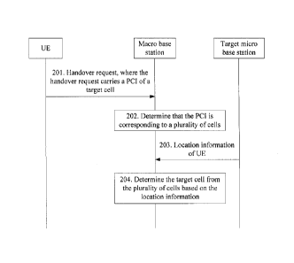
201. A macro base station receives a handover request sent by UE, where the
handover
request carries a PCI of a target second cell.
After performing cell measurement, the UE determines a PCI of a target cell to
which the
UE is to be handed over. Then, the UE sends a handover request to a serving
base station, and
reports a measurement result to the serving base station. A process in which
the UE performs
cell measurement and reports the measurement result may be the same as that in
the prior art.
For brevity, details are not described herein.
The macro base station (that is, an example of a first base station) receives
the handover
request sent by the UE, where the handover request is used to indicate that
the UE requests to
be handed over from a serving cell to the target cell, and the handover
request carries the PCI
of the target cell.
202. The macro base station determines that the PCI is corresponding to a
plurality of
second cells.
Referring to the application scenario shown in FIG. 1, if the PCI of the
target cell carried
in the handover request is 100, there are two cells whose PCIs are 100, that
is, cells
corresponding to the micro base station B and the micro base station C. In
this case, the macro
base station cannot determine, based on PCI-100, whether the target cell to
which the UE
needs to be handed over is a cell corresponding to the micro base station or a
cell
corresponding to the micro base station C.
203. The macro base station receives location information of the UE sent by a
target
micro base station.
It should be understood that the target micro base station herein is a micro
base station
corresponding to the target cell in a plurality of neighboring cells within a
coverage range of
the macro base station.
12
CA 03025568 2018-11-26
The location information of the UE is obtained by the target micro base
station (that is,
an example of a target second base station) based on configuration
information. The
configuration information is used to indicate a time-frequency resource used
when the UE
sends a sounding reference signal (Sounding Reference Signal, SRS) to the
macro base
station.
Optionally, in this embodiment of the present invention, each micro base
station stores
the configuration information. Based on the time-frequency resource (for ease
of
distinguishing and understanding, hereinafter referred to as a time-frequency
resource #A)
indicated by the configuration information, all micro base stations perform
SRS signal
detection on the time-frequency #A.
If the micro base station C cannot detect an SRS signal on the time-frequency
resource
#A, it indicates that "the UE has left" or "the UE is still far away".
Therefore, the cell to which
the UE needs to be handed over is not the cell corresponding to the micro base
station C.
If the micro base station B receives an SRS signal on the time-frequency
resource #A, it
indicates that "the UE is approaching" or "the UE has been in a cell
corresponding to the
micro base station B". In this case, the micro base station B obtains the
location information
of the UE.
Optionally, before receiving the location information sent by the micro base
station, the
macro base station may also send the configuration information to all micro
base stations.
In this embodiment of the present invention, the configuration information may
be
pre-stored by the micro base station, or may be sent by the macro base station
to each micro
base station after the macro base station receives the handover request of the
UE. In this way,
each micro base station may perform signal detection based on the time-
frequency resource
indicated by the configuration information, so as to determine whether the UE
is approaching
the micro base station.
It should be noted that, for brevity, only the target micro base station is
shown in the
schematic interaction diagram in FIG. 3. Actually, in this embodiment of the
present invention,
the macro base station sends the configuration information to all micro base
stations in a
coverage area of a macro cell. For example, in FIG. 2, a base station
corresponding to the cell
A sends configuration information to base stations corresponding to all
neighboring cells (that
13
CA 03025568 2018-11-26
is, the cell B, the cell C, and the cell D). In other words, the base stations
respectively
corresponding to the cell B, the cell C, and the cell D receive the
configuration information,
and perform SRS signal detection on a time-frequency resource indicated by the
configuration
information.
It should also be noted that in this embodiment of the present invention,
description is
provided by using only an example in which the macro base station sends
configuration
information of one UE. It may be understood that when there is a plurality of
UEs in the
coverage area of the macro cell corresponding to the macro base station, the
configuration
information generated by the macro base station includes time-frequency
resources used when
the plurality of UEs send SRS information to the macro base station.
In this embodiment of the present invention, the configuration information is
generated
(or configured) by the macro base station. In addition, a process in which the
macro base
station generates the configuration information is the same as that in the
prior art. Details are
not described herein.
It should be noted that, in this embodiment of the present invention, the
location
information of the UE is information that "the UE is approaching".
It should be understood that after a micro base station receives, on the time-
frequency
resource, an SRS signal sent by the UE to the macro base station, the micro
base station may
learn of, by decoding the SRS signal, the UE sending the SRS signal. In other
words, in this
embodiment of the present invention, the macro base station may configure
different
time-frequency resources for different UEs, so that each UE uses a time-
frequency resource
different from that used by any other UE. The macro base station sends
configuration
information to each micro base station. The micro base station performs SRS
signal detection
based on a time-frequency resource indicated by the configuration information.
When a micro
base station receives an SRS signal on a time-frequency resource, the micro
base station may
learn of, based on a correspondence between UE and a time-frequency resource,
UE sending
the SRS signal on the time-frequency resource, and then send location
information of the UE
to the macro base station. Alternatively, the macro base station may configure
a same
time-frequency resource for different UEs, and distinguish between different
UEs in a code
division manner. In this way, the micro base station may determine, by
decoding the received
14
CA 03025568 2018-11-26
SRS signal, the UE sending the SRS signal, and send the location information
of the UE to
the macro base station.
204. The macro base station determines, based on the location information, a
target cell
from a plurality of cells corresponding to a PCI reported by the UE.
After receiving the location information of the UE sent by the micro base
station B, the
macro base station may learn that a micro base station that the UE is
approaching is the micro
base station B. Therefore, the target cell to which the UE needs to be handed
over is a cell
corresponding to the micro base station B. In this way, the macro base station
can determine,
from the micro base station B and the micro base station C, that the target
micro base station
is the micro base station B, not the micro base station C. In other words,
once the micro base
station B is determined, it is determined that a cell corresponding to the
micro base station B
is the target cell.
It should be understood that, in this embodiment of the present invention, if
a plurality of
micro base stations simultaneously detect the SRS signal sent by the UE to the
macro base
station, and send the location information of the UE to the macro base
station, the macro base
station may select, from the plurality of cells based on strength, quality, or
the like of the SRS
signal received by each micro base station, the target cell to which the UE
needs to be handed
over.
For example, still referring to FIG. 1, it is assumed that both the micro base
station B and
the micro base station C detect the SRS signal sent by the UE to the macro
base station, and
send location information that "the UE is approaching" to the macro base
station. In this case,
the location information sent to the macro base station by the micro base
station B and the
micro base station C carries strength, quality, or the like of the received
SRS signal. It may be
understood that, because the UE is continuously approaching the micro base
station B, in
comparison, strength of the SRS signal received by the micro base station B
should be greater
than strength of the SRS signal received by the micro base station C. In this
case, the macro
base station may also determine, from the micro base station B and the micro
base station C
with reference to the strength, quality, and the like of the SRS signals
received by the micro
base stations, the micro base station B that receives the SRS signal with
greater strength, as
the target micro base station. In this way, the target cell is determined.
CA 03025568 2018-11-26
Optionally, in an embodiment, the location information carries a CGI of the
target cell.
In this embodiment of the present invention, when the target base station
sends the
location information of the UE to the macro base station, the CGI of the
target cell may be
carried in the location information. In this way, after receiving the CGI of
the target cell sent
by the target base station, the macro base station may determine the target
cell from the
plurality of cells with the same PCI based on the CGI of the target cell.
It should be noted that a CGI is a cell global identity, and can uniquely
identify a cell.
After receiving the CGI of the target cell, the macro base station may
determine a unique
target cell from the plurality of cells.
According to the cell handover method in this embodiment of the present
invention, the
base station participates in determining a location of the user equipment, so
that in the case of
target cell PCI confusion, the base station can determine, based on the
location information of
the user equipment, the target cell from the plurality of cells with the same
PCI, to complete
handover. Compared with the prior art, cell handover can be completed without
increasing a
delay.
In addition, in the prior art, when PCI confusion occurs, the base station
configures a
parameter for the UE to read a CGI. This may result in a reading failure risk
and cause a
handover failure. However, in this embodiment of the present invention, a
neighboring base
station (in this case, the neighboring base station is the target base
station) reports the location
information of the UE to the serving base station after detecting the location
information of
the UE, thereby avoiding a handover failure caused by a possible CGI reading
failure.
Therefore, a handover success rate can be improved.
Scenario 2:
FIG. 4 is a schematic interaction diagram of a cell handover method according
to another
embodiment of the present invention. As shown in FIG. 4, the method includes
the following
steps.
301. A macro base station sends configuration information to a control node.
It should be understood that, in this embodiment of the present invention, the
control
node may be an access gateway (Access Gateway, AC) or a virtual eNB. This is
not limited in
this embodiment of the present invention.
16
CA 03025568 2018-11-26
Similar to the descriptions in the scenario 1, the configuration information
may be
pre-stored in the control node; or the configuration information may be sent
by the macro
base station to the control node after the macro base station receives a
handover request sent
by UE; or the configuration information is pre-stored by the control node, but
when the
.. configuration information configured by the macro base station is changed,
the macro base
station sends reconfigured configuration information to the control node. This
is not limited in
this embodiment of the present invention.
302. The control node sends the configuration information to each micro base
station.
The configuration information is used to indicate a time-frequency resource
used when
the UE sends an SRS signal to the macro base station. For the configuration
information,
reference may be made to the foregoing descriptions. Details are not described
herein again.
It should be understood that "each micro base station" herein includes all
micro base
stations within a coverage area of a macro cell corresponding to the macro
base station. In
other words, "each micro base station" includes base stations corresponding to
all neighboring
cells of the macro cell.
303. The micro base station performs SRS signal detection on a time-frequency
resource
indicated by the configuration information.
Specifically, the micro base station (including a target micro base station)
performs SRS
signal detection in an SRS timeslot of the macro base station. If the SRS
signal is received, it
indicates that "the UE is approaching". If no SRS signal is received, it
indicates that "the UE
has left" or "the UE is still far away".
304. The control node receives location information of UE sent by a target
micro base
station.
Optionally, the target micro base station may send the location information of
the UE to
the macro base station, and the macro base station forwards the location
information of the
UE to the control node. In FIG. 4, description is provided by using only an
example in which
the target micro base station directly sends the location information of the
UE to the control
node. This embodiment of the present invention sets no limitation thereto.
305. The macro base station receives a measurement report sent by the UE,
where the
measurement report carries a PCI of a target cell.
17
CA 03025568 2018-11-26
It should be understood that, before the macro base station receives a
measurement
report sent by the UE in step 305, the macro base station needs to send a
handover
measurement instruction to the UE, to instruct the UE to perform neighboring
cell
measurement. After performing the neighboring cell measurement, the UE sends a
measurement report to the macro base station, where the measurement report
carries the PCI
of the target cell.
It should be noted that, the UE may send a measurement report to the macro
base station
periodically or based on an event. A report process is similar to that in the
prior art, and details
are not described herein.
306. The macro base station sends the PCI of the target cell to the control
node.
Similar to step 304, in FIG. 4, description is provided by using only an
example in which
the macro base station sends the PCI to the control node after receiving the
PCI of the target
cell reported by the UE. Obviously, the UE may alternatively directly send the
PCI of the
target cell to the control node.
307. The control node determines the target cell based on the location
information of the
UE sent by the target miCro base station and the PCI of the target cell.
The control node first determines a plurality of cells (including the target
cell)
corresponding to the PCI, and then determines, from the plurality of cells
with reference to
the location information of the UE, a cell that the UE is approaching as the
target cell.
After determining the target cell, the control node sends a handover
instruction to the
target cell, to complete cell handover.
It should be understood that the macro base station in FIG. 3 and FIG. 4 is an
example of
the first base station according to the embodiments of the present invention.
The target micro
base station is an example of a target second base station in the embodiments
of the present
invention. Correspondingly, the macro cell is an example of a first cell, and
the plurality of
cells corresponding to the plurality of micro base stations are an example of
the plurality of
second cells according to the embodiments of the present invention.
It should be noted that the foregoing uses only the scenario 1 and the
scenario 2 as
examples to describe the cell handover method in this embodiment of the
present invention.
This should not be construed as any limitation on the protection scope of the
embodiments of
18
CA 03025568 2018-11-26
the present invention. Application of the cell handover method in this
embodiment of the
present invention in another application scenario should also fall within the
protection scope
of the embodiments of the present invention.
According to the cell handover method in this embodiment of the present
invention, the
base station can correctly determine the target cell from the plurality of
cells with the same
PCI by determining the location of the user equipment, without additional
signaling exchange.
Therefore, when PCI confusion occurs, cell handover can be completed without
increasing a
delay.
The foregoing details the cell handover method in the embodiments of the
present
invention with reference to FIG. 1 to FIG. 4. The following describes a base
station and a
control node used for cell handover in the embodiments of the present
invention with
reference to FIG. 5 to FIG. 7.
FIG. 5 is a schematic diagram of a base station 400 according to an embodiment
of the
present invention. As shown in FIG. 5, the base station 400 includes:
a receiving unit 410, configured to receive a handover request sent by UE,
where the handover request is used to indicate that the UE requests to be
handed
over to a target second cell of at least two second cells, and the handover
request
carries a physical cell identifier PCI of the target second cell; and
a processing unit 420, configured to determine that the PCI is corresponding
to a plurality of second cells; where
the receiving unit 410 is further configured to receive location information
of
the UE sent by a target second base station of at least two second base
stations that
is corresponding to the target second cell, where the location information is
obtained by the target second base station based on the configuration
information;
and
the processing unit 420 is further configured to determine the target second
cell from the plurality of second cells based on the location information.
The foregoing and other operations or functions of units in the base station
400 in this
embodiment of the present invention are used to implement a corresponding
procedure
performed by the first base station in the cell handover method in the
embodiments of the
19
CA 03025568 2018-11-26
present invention. For brevity, details are not described herein again.
Therefore, according to the cell handover method in this embodiment of the
present
invention, when PCI confusion occurs, the target second base station
determines a location of
the user equipment, and sends the location information of the user equipment
to the first base
station, so that the first base station can correctly determine the target
cell. Because no
additional signaling exchange is required, a cell handover can be implemented
without
increasing a delay.
FIG. 6 is a schematic diagram of a base station 500 according to an embodiment
of the
present invention. As shown in FIG. 6, the base station 500 includes:
an obtaining unit 510, configured to obtain location information of UE based
on configuration information; and
a sending unit 520, configured to send the location information to a first
base
station, so that after receiving a handover request sent by the UE, the first
base
station determines, based on the location information from a plurality of
second
cells corresponding to a physical cell identifier PCI of a target second cell
carried
in the handover request, the target second cell to which the UE needs to be
handed
over, where the base station is a base station of at least two base stations
that is
corresponding to the target second cell.
The foregoing and other operations or functions of units in the base station
500 in this
embodiment of the present invention are used to implement a corresponding
procedure
performed by the target second base station in the embodiments of the present
invention. For
brevity, details are not described herein again.
Therefore, according to the cell handover method in this embodiment of the
present
invention, when PCI confusion occurs, the target second base station
determines a location of
the user equipment, and sends the location information of the user equipment
to the first base
station, so that the first base station can correctly determine the target
cell. Because no
additional signaling exchange is required, a cell handover can be implemented
without
increasing a delay.
FIG. 7 is a schematic diagram of a control node 600 according to an embodiment
of the
present invention. As shown in FIG. 7, the control node 600 includes:
CA 03025568 2018-11-26
an obtaining unit 610, configured to obtain a handover request, where the
handover request is used to indicate that UE requests to be handed over to a
target
second cell of at least two second cells, and the handover request carries a
physical
cell identifier PCI of the target second cell; and
a processing unit 620, configured to determine that the PCI is corresponding
to a plurality of second cells; where
the obtaining unit 610 is further configured to obtain location information of
the UE; and
the processing unit 620 is further configured to determine the target second
cell from the plurality of second cells based on the location information.
The foregoing and other operations or functions of units in the control node
600 in this
embodiment of the present invention are used to implement a corresponding
procedure
performed by the control node in the embodiments of the present invention. For
brevity,
details are not described herein again.
Therefore, according to the cell handover method in this embodiment of the
present
invention, when PCI confusion occurs, a target second base station determines
a location of
the user equipment, and sends the location information of the user equipment
to the control
node, so that the control node can correctly determine the target cell.
Because no additional
signaling exchange is required, a cell handover can be implemented without
increasing a
delay.
The foregoing details the cell handover method in the embodiments of the
present
invention with reference to FIG. 5 to FIG. 7. The following describes a base
station and a
control node in the embodiments of the present invention with reference to
FIG. 8 to FIG. 10.
FIG. 8 is a schematic structural diagram of a base station 700 according to an
embodiment of the present invention. The base station 700 is configured in a
communications
system including at least two second base stations and user equipment UE,
where the base
station is corresponding to a first cell, the first cell is a serving cell of
the UE, the at least two
second base stations are corresponding to at least two second cells, the at
least two second
cells are neighboring cells of the first cell, the at least two second cells
are in one-to-one
correspondence with at least two cell global identities CGIs, each CGI is used
to uniquely
21
CA 03025568 2018-11-26
identify a corresponding second cell in the communications system, each second
base station
stores configuration information, and the configuration information is used to
indicate a
time-frequency resource used when the UE sends a sounding reference signal SRS
to the base
station. As shown in FIG. 8, the base station 700 includes a receiver 710, a
transmitter 720, a
processor 730, a memory 740, and a bus system 750. The receiver 710, the
transmitter 720,
the processor 730, and the memory 740 are connected by using the bus system
750. The
memory 740 is configured to store an instruction, and the processor 730 is
configured to
execute the instruction stored in the memory 740, to control the receiver 710
to receive a
signal and control the transmitter 720 to send a signal.
The receiver 710 is configured to receive a handover request sent by the UE,
where the
handover request is used to indicate that the UE requests to be handed over to
a target second
cell of the at least two second cells, and the handover request carries a
physical cell identifier
PCI of the target second cell.
The processor 730 is configured to determine that the PCI is corresponding to
a plurality
of second cells.
The receiver 710 is further configured to receive location information of the
UE sent by
a target second base station of the at least two second base stations that is
corresponding to the
target second cell, where the location information is obtained by the target
second base station
based on the configuration information.
The processor 730 is further configured to determine the target second cell
from the
plurality of second cells based on the location information.
It should be understood that in this embodiment of the present invention, the
processor
730 may be a central processing unit (central processing unit, "CPU" for
short), or the
processor 730 may be another general purpose processor, a digital signal
processor (DSP), an
application-specific integrated circuit (ASIC), a field programmable gate
array (FPGA) or
another programmable logic device, a discrete gate or transistor logic device,
a discrete
hardware component, or the like. The general purpose processor may be a
microprocessor, or
the processor may be any conventional processor, or the like.
The memory 740 may include a read-only memory and a random access memory, and
provide an instruction and data to the processor 830. A part of the memory 740
may further
22
CA 03025568 2018-11-26
include a non-volatile random access memory. For example, the memory 740 may
further
store device type information.
In addition to a data bus, the bus system 750 may include a power bus, a
control bus, a
status signal bus, and the like. However, for clear description, various buses
are marked as the
bus system 750 in the figure.
During implementation, the steps of the foregoing method may be implemented by
using
an integrated logic circuit of hardware in the processor 730 or by using an
instruction in a
form of software. The steps of the cell handover method disclosed with
reference to the
embodiments of the present invention may be directly performed by using a
hardware
processor, or may be performed by using a combination of hardware in the
processor and a
software module. The software module may be located in a storage medium mature
in the art
such as a random access memory, a flash memory, a read-only memory, a
programmable
read-only memory or electrically erasable programmable memory, or a register.
The storage
medium is located in the memory 740. The processor 730 reads information in
the memory
740 and performs the steps of the foregoing method in combination with the
hardware of the
processor. To avoid repetition, details are not described herein again.
The foregoing and other operations or functions of units in the base station
700 in this
embodiment of the present invention are used to implement a corresponding
procedure
performed by the first base station in the embodiments of the present
invention. For brevity,
details are not described herein again.
Therefore, when PCI confusion occurs, the base station in this embodiment of
the
present invention receives the location information of the user equipment sent
by the target
second base station, and can correctly determine the target cell. Because no
additional
signaling exchange is required, a cell handover can be implemented without
increasing a
delay.
FIG. 9 is a schematic structural diagram of a base station 800 according to an
embodiment of the present invention. The base station 800 is configured in a
communications
system including a first base station, at least two base stations, and user
equipment UE, where
the first base station is corresponding to a first cell, the first cell is a
serving cell of the UE,
the at least two base stations are corresponding to at least two second cells,
the at least two
23
CA 03025568 2018-11-26
second cells are neighboring cells of the first cell, the at least two second
cells are in
one-to-one correspondence with at least two cell global identities CGIs, each
CGI is used to
uniquely identify a corresponding second cell in the communications system,
each base
station stores configuration information, and the configuration information is
used to indicate
a time-frequency resource used when the UE sends a sounding reference signal
SRS to the
first base station. As shown in FIG. 9, the base station 800 includes a
receiver 810, a
transmitter 820, a processor 830, a memory 840, and a bus system 850. The
receiver 810, the
transmitter 820, the processor 830, and the memory 840 are connected by using
the bus
system 850. The memory 840 is configured to store an instruction, and the
processor 830 is
configured to execute the instruction stored in the memory 840, to control the
receiver 810 to
receive a signal and control the transmitter 820 to send a signal.
The processor 830 is configured to obtain location information of the UE based
on the
configuration information.
The transmitter 820 is configured to send the location information to the
first base station,
so that after receiving a handover request sent by the UE, the first base
station determines,
based on the location information from a plurality of second cells
corresponding to a physical
cell identifier PCI of a target second cell carried in the handover request,
the target second cell
to which the UE needs to be handed over, where the target second cell is a
base station of the
at least two second base stations that is corresponding to the target second
cell.
It should be understood that in this embodiment of the present invention, the
processor
830 may be a central processing unit (central processing unit, "CPU" for
short), or the
processor 830 may be another general purpose processor, a digital signal
processor (DSP), an
application-specific integrated circuit (ASIC), a field programmable gate
array (FPGA) or
another programmable logic device, a discrete gate or transistor logic device,
a discrete
hardware component, or the like. The general purpose processor may be a
microprocessor, or
the processor may be any conventional processor, or the like.
The memory 840 may include a read-only memory and a random access memory, and
provide an instruction and data to the processor 830. A part of the memory 840
may further
include a non-volatile random access memory. For example, the memory 840 may
further
store device type information.
24
CA 03025568 2018-11-26
In addition to a data bus, the bus system 850 may include a power bus, a
control bus, a
status signal bus, and the like. However, for clear description, various buses
are marked as the
bus system 850 in the figure.
During implementation, the steps of the foregoing method may be implemented by
using
an integrated logic circuit of hardware in the processor 830 or by using an
instruction in a
form of software. The steps of the cell handover method disclosed with
reference to the
embodiments of the present invention may be directly performed by using a
hardware
processor, or may be performed by using a combination of hardware in the
processor and a
software module. The software module may be located in a storage medium mature
in the art
such as a random access memory, a flash memory, a read-only memory, a
programmable
read-only memory or electrically erasable programmable memory, or a register.
The storage
medium is located in the memory 840. The processor 830 reads information in
the memory
840 and performs the steps of the foregoing method in combination with the
hardware of the
processor. To avoid repetition, details are not described herein again.
The foregoing and other operations or functions of units in the base station
800 in this
embodiment of the present invention are used to implement a corresponding
procedure
performed by the target second base station in the embodiments of the present
invention. For
brevity, details are not described herein again.
Therefore, when PCI confusion occurs, the base station in this embodiment of
the
present invention determines a location of the user equipment, and sends the
location
information of the user equipment to the first base station, so that the first
base station can
correctly determine the target cell. Because no additional signaling exchange
is required, a
cell handover can be implemented without increasing a delay.
FIG. 10 is a schematic structural diagram of a control node 900 according to
an
embodiment of the present invention. The control node 900 is configured in a
communications system including a first base station, at least two second base
stations, and
user equipment UE, where the first base station is corresponding to a first
cell, the first cell is
a serving cell of the UE, the at least two second base stations are
corresponding to at least two
second cells, the at least two second cells are neighboring cells of the first
cell, the at least two
second cells are in one-to-one correspondence with at least two cell global
identities CGIs,
CA 03025568 2018-11-26
each CGI is used to uniquely identify a corresponding second cell in the
communications
system, each second base station stores configuration information, and the
configuration
information is used to indicate a time-frequency resource used when the UE
sends a sounding
reference signal SRS to the first base station. As shown in FIG. 10, the
control node 900
includes a receiver 910, a transmitter 920, a processor 930, a memory 940, and
a bus system
950. The receiver 910, the transmitter 920, the processor 930, and the memory
940 are
connected by using the bus system 950. The memory 940 is configured to store
an instruction,
and the processor 930 is configured to execute the instruction stored in the
memory 940, to
control the receiver 910 to receive a signal and control the transmitter 920
to send a signal.
The receiver 910 is configured to receive a handover request, where the
handover request is
used to indicate that the UE requests to be handed over to a target second
cell of the at least
two second cells, and the handover request carries a physical cell identifier
PCI of the target
second cell.
The processor 930 is configured to determine that the PCI is corresponding to
a plurality
of second cells.
The receiver 910 is further configured to receive location information of the
UE.
The processor 930 is further configured to determine the target second cell
from the
plurality of second cells based on the location information.
It should be understood that in this embodiment of the present invention, the
processor
930 may be a central processing unit (central processing unit, "CPU" for
short), or the
processor 930 may be another general purpose processor, a digital signal
processor (DSP), an
application-specific integrated circuit (ASIC), a field programmable gate
array (FPGA) or
another programmable logic device, a discrete gate or transistor logic device,
a discrete
hardware component, or the like. The general purpose processor may be a
microprocessor, or
the processor may be any conventional processor, or the like.
The memory 940 may include a read-only memory and a random access memory, and
provide an instruction and data to the processor 930. A part of the memory 940
may further
include a non-volatile random access memory. For example, the memory 940 may
further
store device type information.
In addition to a data bus, the bus system 950 may include a power bus, a
control bus, a
26
CA 03025568 2018-11-26
status signal bus, and the like. However, for clear description, various buses
are marked as the
bus system 950 in the figure.
During implementation, the steps of the foregoing method may be implemented by
using
an integrated logic circuit of hardware in the processor 930 or by using an
instruction in a
form of software. The steps of the cell handover method disclosed with
reference to the
embodiments of the present invention may be directly performed by using a
hardware
processor, or may be performed by using a combination of hardware in the
processor and a
software module. The software module may be located in a storage medium mature
in the art
such as a random access memory, a flash memory, a read-only memory, a
programmable
read-only memory or electrically erasable programmable memory, or a register.
The storage
medium is located in the memory 940. The processor 930 reads information in
the memory
940 and performs the steps of the foregoing method in combination with the
hardware of the
processor. To avoid repetition, details are not described herein again.
The foregoing and other operations or functions of units in the control node
900 in this
embodiment of the present invention are used to implement a corresponding
procedure
performed by the control node in the cell handover method in the embodiments
of the present
invention. For brevity, details are not described herein again.
Therefore, when PCI confusion occurs, the control node in this embodiment of
the
present invention can correctly determine the target cell by obtaining the
location information
of the UE. Because no additional signaling exchange is required, a cell
handover can be
implemented without increasing a delay.
It should be understood that sequence numbers of the foregoing processes do
not mean
execution sequences in various embodiments of the present invention. The
execution
sequences of the processes should be determined according to functions and
internal logic of
the processes, and should not be construed as any limitation on the
implementation processes
of the embodiments of the present invention.
A person of ordinary skill in the art may be aware that, in combination with
the examples
described in the embodiments disclosed in this specification, units and
algorithm steps may be
implemented by electronic hardware, computer software, or a combination
thereof. To clearly
describe the interchangeability between the hardware and the software, the
foregoing has
27
CA 03025568 2018-11-26
generally described compositions and steps of each example according to
functions. Whether
the functions are performed by hardware or software depends on particular
applications and
design constraint conditions of the technical solutions. A person skilled in
the art may use
different methods to implement the described functions for each particular
application, but it
should not be considered that the implementation goes beyond the scope of the
present
invention.
It may be clearly understood by a person skilled in the art that, for the
purpose of
convenient and brief description, for a detailed working process of the
foregoing system,
apparatus, and unit, reference may be made to a corresponding process in the
foregoing
.. method embodiments, and details are not described herein again.
In the several embodiments provided in this application, it should be
understood that the
disclosed system, apparatus, and method may be implemented in other manners.
For example,
the described apparatus embodiment is merely an example. For example, the unit
division is
merely logical function division and may be other division in actual
implementation. For
example, a plurality of units or components may be combined or integrated into
another
system, or some features may be ignored or not performed. In addition, the
displayed or
discussed mutual couplings or direct couplings or communication connections
may be
implemented through some interfaces, indirect couplings or communication
connections
between the apparatuses or units, or electrical connections, mechanical
connections, or
.. connections in other forms.
The units described as separate parts may or may not be physically separate,
and parts
displayed as units may or may not be physical units, may be located in one
position, or may
be distributed on a plurality of network units. A part or all of the units may
be selected
according to actual needs to achieve the objectives of the solutions of the
embodiments of the
present invention.
In addition, functional units in the embodiments of the present invention may
be
integrated into one processing unit, or each of the units may exist alone
physically, or two or
more units may be integrated into one unit. The integrated unit may be
implemented in a form
of hardware, or may be implemented in a form of a software functional unit.
When the integrated unit is implemented in the form of a software functional
unit and
28
CA 03025568 2018-11-26
sold or used as an independent product, the integrated unit may be stored in a
computer-readable storage medium. Based on such an understanding, the
technical solutions
of the present invention essentially, or the part contributing to the prior
art, or all or a part of
the technical solutions may be implemented in the form of a software product.
The software
product is stored in a storage medium and includes several instructions for
instructing a
computer device (which may be a personal computer, a server, a network device,
or the like)
to perform all or a part of the steps of the methods described in the
embodiments of the
present invention. The foregoing storage medium includes: any medium that can
store
program code, such as a USB flash drive, a removable hard disk, a read-only
memory (ROM,
.. Read-Only Memory), a random access memory (RAM, Random Access Memory), a
magnetic
disk, or an optical disc.
The foregoing descriptions are merely specific embodiments of the present
invention, but
are not intended to limit the protection scope of the present invention. Any
modification or
replacement readily figured out by a person skilled in the art within the
technical scope
disclosed in the present invention shall fall within the protection scope of
the present
invention. Therefore, the protection scope of the present invention shall be
subject to the
protection scope of the claims.
29