Note: Descriptions are shown in the official language in which they were submitted.
CA 03026489 2018-12-04
WO 2017/215801 Al
INJECTION MOULDING TOOL WITH ADJUSTABLE CORE-CENTRING
DEVICE
Technical field
The invention relates to an injection moulding tool having
at least one cavity for producing thin-walled, container-
like injection-moulded articles, particularly cups, tubes,
tube heads, small tubes, bottle blanks or syringes,
comprising a die holding plate, which has at least one
cavity-forming die; a core-holding plate, which has at
least one core unit with cavity-forming core; at least one
stripping ring for stripping the injection-moulded article
from at least one core, wherein the at least one stripping
ring is arranged between core-holding plate and die holding
plate; and at least one adjustable core-centring device for
the fine alignment of the at least one core with respect to
the at least one die.
Technical background
During the production of thin-walled, container-like
injection-moulded articles, particularly cups, tubes, tube
heads, small tubes, bottle blanks or syringes, a uniform
wall thickness is very important, as even small deviations
in the wall thickness occurring during the cooling and
unmoulding of the container may lead to pronounced
deformations of the container due to volumetric shrinkage
which occurs.
The cavities for such injection-moulded articles are always
constructed by means of a die and a core arranged therein.
In order to obtain a uniform wall thickness, the position
of the core in a separation plane perpendicular to the
closing direction of the moulding tool must therefore be
aligned such that it is centred with the cavity-forming
die. In multi-cavity moulding tools, each core is centred
CA 03026489 20112-134
- 2 -
separately in this case. A separate centring of the cores
in the respective die is important, in order to be able to
obtain injection-moulded articles with uniform wall
thicknesses with all cavities.
Known injection moulding tools for such thin-walled,
container-like injection-moulded articles, such as for
example the injection moulding tool illustrated in Fig. 1,
comprise a die holding plate, in which at least one cavity-
forming die unit or die is secured, a core-holding plate,
on which at least one cavity-forming core unit or a core is
held, and a stripping ring, which is arranged in a
positive-fitting manner in a recess of the core unit and
can be moved counter to the closing direction, in order to
strip the finished injection-moulded article from the core
after the opening of the moulding tool. The core or the
core unit is mounted for setting the centring in a floating
manner on the core-holding plate and is fixed in its
position on the core-holding plate once correct centring
has taken place by means of fastening means.
For fine centring of the core with respect to the die, a
core-centring device is arranged between die unit and core
unit. The core-centring device comprises a plurality of -
at most four - centring strips, which have a centring
surface which is inclined compared to the closing direction
of the injection moulding tool and are supported on a
correspondingly inclined contact surface of the core unit.
By adding or removing adjustment films at the centring
strips, the core can be centred exactly in the associated
die. Each centring strip therefore forms a centring surface
on the core unit, which corresponds to a centring surface
on the die unit. As soon as the core and die are centred
with respect to one another, the core unit is fixed on the
core-holding plate and the moulding tool is ready for the
production of the injection-moulded articles. If there are
a plurality of core units, air gaps are present between
CA 03026489 20112-134
- 3 -
adjacent core units for the individual centring of the
individual units.
It is disadvantageous for the known structure, that the
stripping ring and in particular the region of the core
unit surrounding the stripping ring with the core-centring
device must be sufficiently large and strongly dimensioned,
in order to withstand large closing forces of 1000 kN or
more. This leads to the diameter of the core units being
substantially larger than the diameter of the cavity, which
has a direct effect on the maximum number of cavities per
moulding tool.
A further disadvantage consists in the fact that, during
initial adjustment or during readjustment, the core-
centring devices are poorly accessible and the injection
moulding tool must be disassembled to a certain extent.
Description of the Invention
It is an object of the invention to specify an injection
moulding tool for producing thin-walled, container-like
injection-moulded articles, particularly cups, tubes, tube
heads, small tubes, bottle blanks or syringes, in which the
centring is easier to adjust and which allows a greater
number of cavities per unit area.
This object is achieved by an injection moulding tool with
the features of Claim 1. The injection moulding tool having
at least one cavity for producing thin-walled, container-
like injection-moulded articles, particularly cups, tubes,
tube heads, small tubes, bottle blanks or syringes,
comprises a die holding plate, which has at least one
cavity-forming die or die unit; a core-holding plate, which
has at least one core unit with cavity-forming core; at
least one stripping ring for stripping the injection-
moulded article from at least one core, wherein the at
CA 03026489 20112-134
- 4 -
least one stripping ring is arranged between core-holding
plate and die holding plate; and at least one adjustable
core-centring device for the exact alignment of the at
least one core in the at least one die. The stripping ring
is held in a floating manner in a stripping plate, which is
arranged between die holding plate and core-holding plate.
The at least one adjustable core-centring device is
arranged between core unit and core-holding plate.
The adjustable core-centring device is as a result arranged
behind the stripping ring between core-holding plate and
core unit in the closing direction and can thus be
positioned closer to the core with respect to a central
axis (core axis) running through the core parallel to the
closing direction. This in turn allows a reduction of the
total diameter of the core units and the individual
cavities of a multi-cavity injection moulding tool can be
arranged closer to one another. As the stripping ring is
held in a floating manner in the stripping plate, it adapts
to a displacement of the core unit for fine centring the
core in the die. In other words, the core unit or the core
is centred from behind by means of the core-holding plate,
in contrast to the prior art where the core unit is centred
at the front by means of the die holding plate.
In the context of this invention, adjustable core centring
device means a core-centring device, by means of which the
position of the core can be displaced in a separation plane
and centred relatively to the die, in order to obtain a
cavity with uniform wall thicknesses. By contrast, the term
fixed plate centring unit means a device using which the
position of the various plates of the injection moulding
tool in the closed state with respect to one another in the
separation plane is determined in a displacement-free
manner. An adjustment of the plate centring unit is not
provided or not possible. The fixed plate centring unit is
used for the fixed alignment and positioning of the
CA 03026489 20112-134
- 5 -
individual plates with respect to one another. The
adjustable core-centring device is used for the fine
adjustment of the core inside the die. Closing direction
means the direction in which the core is pushed relatively
to the die when closing the moulding tool. Front is
consequently defined by the front narrower region of the
core.
To open the injection moulding tool, first the die holding
plate with the at least one die is separated, along a first
separation line between die holding plate and stripping
plate, from the stripping plate together with the core-
holding plate with the at least one core unit.
Subsequently, the injection-moulded article is stripped
from the core in that the stripping plate is separated and
advanced along a second separation line between stripping
plate and core-holding plate using the stripping ring.
In the closed state, the core unit or the core extends .
through the stripping ring or the stripping plate into the
die and forms the cavity together with the die. The cavity
is additionally formed by the stripping ring in a small
region surrounding the core. The injection nozzle or the
injection region may be arranged at the front, at the rear
or at the side.
In some embodiments, at least one first fixed plate
centring unit can be arranged between die holding plate and
stripping plate and at least one second fixed plate
centring unit can be arranged between stripping plate and
core-holding plate, wherein the first and second plate
centring units define a fixed, predetermined positioning of
the die holding plate, stripping plate and core-holding
plate with respect to one another in the closed state of
the injection moulding tool. Die holding plate, stripping
plate and core-holding plate are thus rigidly fixed with
respect to one another in the separation plane and the
CA 03026489 20112-134
- 6 -
position of the core in the die is then finely adjusted by
means of the adjustable core-centring device.
In a few embodiments, an air gap is present along a
peripheral outer surface of the stripping ring. In this
manner, the stripping ring is mounted in a movable manner
in a separation plane, in order to allow a displacement of
the core unit for centring the core.
In some embodiments, the at least one adjustable core-
centring device can be arranged on the stripping plate side
in the core-holding plate. In a stripping plate side
arrangement, the core-centring device is accessible for a
renewed or correcting fine centring of the core when the
injection moulding tool is completely open, i.e. when the
stripping plate is advanced completely in the direction of
the die holding plate during maintenance, without the
injection moulding tool having to be partially
disassembled.
In some embodiments, the stripping ring can be held in the
stripping plate in a floating manner using at least one
fastening element. The fastening element can form the first
fixed plate centring unit between die holding plate and
stripping plate at the same time. The fastening element can
alternatively comprise two securing pins arranged parallel
to one another and parallel to the separation plane, which
secure the stripping ring at two opposite sides directly in
the stripping plate or indirectly in the stripping plate,
e.g. by means of the first fixed plate centring unit. The
securing pins have sufficient play, so that the stripping
ring is mounted in the stripping plate in a floating
manner.
In some embodiments, the stripping ring can have a conical
inner surface complementary to a conical sealing region,
i.e. a conical outer surface of the core unit. Stripping
CA 03026489 2018-12-04
- 7 -
ring and core unit are in this case constructed in such a
manner, that during the closing of the injection moulding
tool, the stripping ring is pushed rearwards through the
die unit in the closing direction, and thus pressed in a
sealing manner against the core unit. In order to achieve
this, the stripping ring can with its conical inner surface
have a prestress compared to the conical outer surface of
the core unit, so that it is pressed by way of the conical
inner surface in a sealing manner against the conical outer
surface of the core unit during the closing of the
injection moulding tool. In other words, the stripping ring
can have a slight overdimension at the front, so that, in
the closed state of the injection moulding tool, it is
pushed rearwards through the die unit and in the process is
pushed against the conical sealing surface of the core unit
in a sealing manner. The cavity, which is delimited to some
extent in the rear region by the stripping ring, is then
closed in a sealing manner. Generally - even in the closed
state of the injection moulding tool - an air gap is
present between the stripping ring and stripping plate and
between the rear end of the stripping ring in the closing
direction and the core-holding plate, the core unit or the
adjustable core-centring device. If, when the moulding tool
is closed, the stripping ring is pushed all the way against
the core-holding plate or core unit (i.e. there is no
longer an air gap present), then the stripping ring 6 may
, also additionally stabilize the position of the core.
In some embodiments, the at least one core-centring device
can have four centring strips with inclined centring
surface arranged evenly around the core unit.
In some embodiments, the stripping ring can have a
surrounding stop on the outer side, so that it is entrained
by the stripping plate, which can be displaced forwards, to
strip the injection-moulded article from the core. The
CA 03026489 20112-134
- 8 -
fastening element for the stripping ring can likewise act
on this surrounding stop.
Short description of the figures
The invention shall be explained in more detail in the
following on the basis of exemplary embodiments in
connection with the drawing(s). In the figures:
Fig. 1 shows a sectional illustration of an injection
moulding tool according to the prior art with a
core-centring device between core unit and die
unit;
Fig. 2 shows a sectional illustration of an injection
moulding tool with a core-side core-centring
device and a floating stripping ring;
Fig. 3 shows a plan view onto a core-centring device; and
Fig. 4 shows a sectional illustration of an injection
moulding tool with a core-side core-centring
device and a floating stripping ring.
Ways of realizing the invention
Fig. 1 shows a sectional illustration of an injection
moulding tool according to the prior art. The injection
moulding tool comprises a die holding plate 2 (only
indicated) having at least one die unit 3, which forms the
cavity-forming die 3', a core-holding plate 4 (only
indicated), having at least one core unit 5, which forms
the cavity-forming core 5', and a stripping ring 6. The
stripping ring 6 is arranged in a positive-fitting manner
in a recess between a core-forming region and a peripheral
region of the core unit, so that to eject the injection-
moulded article, it is possible to be advanced forwards
along the core 5' by means of an actuating device 8. The
core unit 5 is mounted in a floating manner on the core-
holding plate 4 and can be fixed after centring has taken
place. For fine centring of the core 5' inside the die 3',
CA 03026489 23113-1134
- 9 -
an adjustable core-centring device 7 is arranged between
the peripheral region of the core unit 5 and a peripheral
region of the die unit 3.
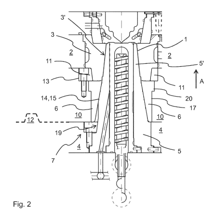
Fig. 2 shows a sectional illustration of an injection
moulding tool with a core-side core-centring device 7 and a
floating stripping ring 11. The injection moulding tool
comprises a die holding plate 2, a core-holding plate 4 and
a stripping plate 10. The die holding plate 2 holds at
least one die unit 3 having a cavity-forming die 3'. The
core-holding plate 4 holds at least one core unit 5 having
a cavity-forming core 5'. A stripping plate 6 is mounted in
the stripping ring 10 in a floating manner. In the closed
state of the moulding tool, one core 5' and one die 3' form
a cavity 1 in each case, which cavity is additionally
delimited by the stripping ring 6 in the rear region. In
this case, parts of the core unit 5 or the core 5' reach
through the stripping ring 6 into the die 3'.
In the injection moulding tool shown, the adjustable core-
centring device 7 has a plurality of, preferably four,
centring strips 18 arranged evenly around the core unit 5
(Fig. 3). The centring strips 18 have an inclined centring
surface 19, which is complementary to an inclined centring
surface on the core unit 5 in each case. The centring
strips 18 can be screwed securely to the core-holding plate
4. For fine centring, adjustment films are then inserted or
removed behind opposite centring strips 18, 18' in each
case until the desired centring of the core 5' is achieved.
At least one first fixed plate centring unit 11 is arranged
between the die holding plate 2 and the stripping plate 10,
which determines a predetermined alignment of the two
plates in the closed state of the moulding tool. A second
fixed plate centring unit 12 is arranged between the
stripping plate 10 and the core-holding plate 4, which
determines a predetermined alignment of the two plates in
CA 03026489 20112-134
- 10 -
the closed state of the moulding tool (indicated dashed in
Figs 2 and 4). In the closed state of the moulding tool,
the relative position of the die holding plate 2, the
stripping plate 10 and the core-holding plate 4 with
respect to one another is therefore fixed. The actual fine
centring of the core 5' inside the die 3' takes place by
means of the adjustable core-centring device 7. The fixed
plate-centring devices 11, 12 have likewise inclined
centring surfaces, which are complementary between the
individual plates 2, 4, 10 in each case.
In the injection moulding tool shown in Fig. 2, the
stripping ring 6 has a peripheral surrounding stop 20 or
flange in the front region. On one side, the stop 20
engages into a shoulder in the stripping plate 10, so that
the stripping ring 7 is entrained forwards for stripping an
injection-moulded article by advancing the stripping plate
along the core 5', and on the other side is held in a
floating manner in the stripping plate 10 by means of a
fastening element 13. The fastening element 13 forms the
first plate centring unit 11 at the same time.
The core unit 5 has a conical outer surface 14 adjacent to
the core 5', which is complementary to a conical inner
surface of the stripping ring 6. The conical inner surface
of the stripping ring 6 has a prestress compared to the
conical outer surface 15 of the core unit (i.e. it is
configured with a slight overdimension at the front), so
that the conical inner surface 15 thereof is pressed
against the conical outer surface 14 of the core unit 5
during the closure of the moulding tool by means of the die
unit 3'. A small air gap 17 is present along a peripheral
outer surface of the stripping ring, i.e. between the
stripping ring 6 and stripping plate 10. In the open state
of the moulding tool, an air gap is present between the
rear region of the stripping ring 6 and the core-holding
plate 4 or the core-centring device 7 or the core unit 5,
CA 03026489 23113-1134
- 11 -
which air gap may still be present in the closed state,
although smaller. If, when the moulding tool is closed, the
stripping ring 6 is pressed all the way against the core-
holding plate 4 or core unit 5 (i.e. there is no longer an
air gap present), then the stripping ring 6 may also
additionally stabilize the position of the core 5'.
Fig. 4 likewise shows a sectional illustration of an
injection moulding tool with a core-side core-centring
device 7 and a floating stripping ring 11. In contrast to
the injection moulding tool from Fig. 2, the stripping ring
11 is held in the stripping plate 10 by means of two
securing pins 21, 21' arranged parallel to one another and
to the separation plane of the moulding tool. The securing
pins 21, 21' have sufficient play in order to ensure the
floating mounting of the stripping ring, but prevent the
stripping ring, which is mounted in a floating manner, from
falling out after the stripping of an injection-moulded
article from the core. In the embodiment shown, the
securing pins 21, 21' are held in the first fixed plate
centring unit 11, which is in turn fastened on the
stripping plate 10. Direct mounting in the stripping plate
is also possible. The securing pins 21, 21' also secure
the stripping ring 6 against twisting.
A surrounding air gap 22 is present along the peripheral
outer surface of the core unit, i.e. between the core unit
5 and the fixed plate centring unit 11, in order to permit
a movement of the core unit 5 for centring the core 5'.
CA 03026489 23113-1134
WO 2017/215801 Al
List of reference numbers
1 Cavity
2 Die holding plate
3, 3' Die unit/die
4 Core-holding plate
5, 5' Core unit/core
6 Stripping ring
7 Adjustable core-centring device
8 Actuating device
Stripping plate
11 First fixed plate centring unit
12 Second fixed plate centring unit
13 Fastening element
14 Conical outer surface
Conical inner surface
16 Rear end of the stripping ring
17 Air gap
18 Centring strip
19 Inclined centring surface
Stop
21, 21' Securing pin
22 Air gap
A Closing direction