Note: Descriptions are shown in the official language in which they were submitted.
CA 03026654 2018-12-05
WO 2017/218349
PCMJS2017/036831
External Charger for an Implantable Medical Device Having at Least One Sense
Coil
Concentric with a Charging Coil For Determining Position
FIELD OF THE INVENTION
[0001] The present invention relates to wireless external chargers for use in
implantable
medical device systems.
BACKGROUND
[0002] Implantable stimulation devices are devices that generate and deliver
electrical stimuli
to body nerves and tissues for the therapy of various biological disorders,
such as pacemakers
to treat cardiac arrhythmia, defibrillators to treat cardiac fibrillation,
cochlear stimulators to
treat deafness, retinal stimulators to treat blindness, muscle stimulators to
produce
coordinated limb movement, spinal cord stimulators to treat chronic pain,
cortical and deep
brain stimulators to treat motor and psychological disorders, and other neural
stimulators to
treat urinary incontinence, sleep apnea, shoulder subluxation, etc. The
description that
follows will generally focus on the use of the invention within a Spinal Cord
Stimulation
(SCS) system. such as that disclosed in U.S. Patent 6,516,227. However, the
present
invention may find applicability in any implantable medical device system,
including a Deep
Brain Stimulation (DBS) system.
[0003] As shown in Figures 1A-1C, a SCS system typically includes an
Implantable Pulse
Generator (IPG) 10 (Implantable Medical Device (IMD) 10 more generally), which
includes
a biocompatible device case 12 formed of a conductive material such as
titanium for
example. The case 12 typically holds the circuitry and battery 14 (Fig. 1C)
necessary for the
IMD 10 to function, although IMDs can also be powered via external RF energy
and without
a battery. The IMD 10 is coupled to electrodes 16 via one or more electrode
leads 18, such
that the electrodes 16 form an electrode array 20. The electrodes 16 are
carried on a flexible
body 22, which also houses the individual signal wires 24 coupled to each
electrode. In the
illustrated embodiment, there are eight electrodes (Ex) on each lead 18,
although the number
of leads and electrodes is application specific and therefore can vary. The
leads 18 couple to
the IMD 10 using lead connectors 26, which are fixed in a non-conductive
header material
28, which can comprise an epoxy for example.
[0004] As shown in the cross-section of Figure 1C, the IMD 10 typically
includes a printed
circuit board (PCB) 30, along with various electronic components 32 mounted to
the PCB 30,
1
CA 03026654 2018-12-05
WO 2017/218349
PCT/US2017/036831
some of which are discussed subsequently. Two coils (more generally, antennas)
are show in
the IMD 10: a telemetry coil 34 used to transmit/receive data to/from an
external controller
(not shown); and a charging coil 36 for charging or recharging the IMD's
battery 14 using an
external charger, which is discussed in detail later.
[0005] Figure 2 shows the IMD 10 in communication with an external charger 50
used to
wirelessly convey power to the IMD 10, which power can be used to recharge the
IMD's
battery 14. The transfer of power from the external charger 50 is enabled by a
primary
charging coil 52. The external charger 50, like the IMD 10, also contains a
PCB 54 on which
electronic components 56 are placed. Again, some of these electronic
components 56 are
discussed subsequently. A user interface 58, including touchable buttons and
perhaps a
display and a speaker, allows a patient or clinician to operate the external
charger 50. A
battery 60 provides power for the external charger 50, which battery 60 may
itself be
rechargeable. The external charger 50 can also receive AC power from a wall
plug. A hand-
holdable housing 62 sized to fit a user's hand contains all of the components.
[0006] Power transmission from the external charger 50 to the IMD 10 occurs
vvirelessly and
transcutaneously through a patient's tissue 25, via inductive coupling. Figure
3 shows details
of the circuitry used to implement such functionality. Primary charging coil
52 in the
external charger 50 is energized via charging circuit 64 with an AC current,
Icharge, to create
an AC magnetic charging field 66 This magnetic field 66 induces a current in
the secondary
charging coil 36 within the IMD 10, providing a voltage across coil 36 that is
rectified (38) to
DC levels and used to recharge the battery 14, perhaps via a battery charging
and protection
circuitry 40 as shown. The frequency of the magnetic field 66 can be perhaps
80 kHz or so.
When charging the battery 14 in this manner, is it typical that the housing 62
of the external
charger 50 touches the patient's tissue 25, perhaps with a charger holding
device or the
patient's clothing intervening, although this is not strictly necessary.
[0007] The IMD 10 can also communicate data back to the external charger 50
during
charging using reflected impedance modulation, which is sometimes known in the
art as Load
Shift Keying (LSK). This involves modulating the impedance of the charging
coil 36 with
data bits (-LSK data") provided by the IMD 10's control circuitry 42 to be
serially
transmitted from the IMD 10 to the external charger 50. For example, and
depending on the
logic state of a bit to be transmitted, the ends of the coil 36 can be
selectively shorted to
ground via transistors 44, or a transistor 46 in series with the coil 36 can
be selectively open
circuited, to modulate the coil 36's impedance. At the external charger 50, an
LSK
demodulator 68 determines whether a logic '0' or '1' has been transmitted by
assessing the
2
CA 03026654 2018-12-05
WO 2017/218349
PCT/US2017/036831
magnitude of AC voltage Vcoil that develops across the external charger's coil
52 in response
to the charging current Icharge and the transmitted data, which data is then
reported to the
external charger's control circuitry 72 for analysis. Such back telemetry from
the IMD 10
can provide useful data concerning charging to the external charger 50, such
as the capacity
of the IMD's battery 14, or whether charging of the battery 14 is complete and
operation of
the external charger 50 and the production of magnetic field 66 can cease. LSK
communications are described further for example in U.S. Patent Application
Publication
2013/0096652.
[0008] External charger 50 can also include one or more thermistors 71, which
can be used to
report the temperature (expressed as voltage Vtherm) of external charger 50 to
its control
circuitry 72, which can in turn control production of the magnetic field 66
such that the
temperature remains within safe limits. See, e.g., USP 8,321,029, describing
temperature
control in an external charging device.
[0009] Vcoil across the external charger's charging coil 52 can also be
assessed by
alignment circuitry 70 to determine how well the external charger 50 is
aligned relative to the
IMD 10. This is important, because it the external charger 50 is not well
aligned to the IM[)
10, the magnetic field 66 produced by the charging coil 52 will not
efficiently be received by
the charging coil 36 in the IMD 10. Efficiency in power transmission can be
quantified as the
"coupling" between the transmitting coil 52 and the receiving coil 36 (1c,
which ranges
between 0 and 1), which generally speaking comprises the extent to which power
expended at
the transmitting coil 52 in the external charger 50 is received at the
receiving coil 36 in the
IMD 10. It is generally desired that the coupling between coils 52 and 36 be
as high as
possible: higher coupling results in faster charging of the IMD battery 14
with the least
expenditure of power in the external charger 50. Poor coupling is disfavored,
as this will
require high power drain (e.g., a high Icharge) in the external charger 50 to
adequately charge
the IMD battery 14. The use of high power depletes the battery 60 in the
external charger 50,
and more importantly can cause the external charger 50 to heat up, and
possibly burn or
injure the patient.
WWI Generally speaking, if the external charger 50 is well aligned with the
IMD 10, then
Vcoil will drop as the charging circuitry 64 provides the charging current
Icharge to the
charging coil 52. Accordingly, alignment circuitry 70 can compare Vcoil,
preferably after it
is rectified 76 to a DC voltage, to an alignment threshold, Vt. If Vcoil < Vt,
then external
charger 50 considers itself to be in good alignment with the underlying IMD
10. If Vcoil >
Vt, then the external charger 50 will consider itself to be out of alignment,
and can indicate
3
CA 03026654 2018-12-05
WO 2017/218349
PCT/US2017/036831
that fact to the patient so that the patient can attempt to move the charger
50 into better
alignment. For example, the user interface 58 of the charger 50 can include an
alignment
indicator 74. The alignment indicator 74 may comprise a speaker (not shown),
which can
"beep" at the patient when misalignment is detected. Alignment indicator 74
can also or
alternatively include one or more Light Emitting Diodes (LED(s); not shown),
which may
similarly indicate misalignment.
[0011] Charger-to-IMD coupling depends on many variables, such as the
permeability of the
materials used in the external charger 50 and the IMD 10, as well materials
inherent in the
environment. Coupling is also affected by the relative positions of the
external charger 50
and IMD 10, as shown in Figures 4A-4C. For best coupling (higher values of k),
it is
preferred that axes around which coils 52 and 36 are wound (52' and 36') are
parallel and
collinear, with the coils 52 and 36 as close as possible (d1) to each other,
as shown in Figure
4A. Distance dl indicates the depth between the external charger 50 and the
IMD 10, and is
generally constant given that the external charger is generally placed on the
patient's tissue
25, and that the IMD 10 has been implanted at a particular depth. Deviations
from these ideal
conditions will generally reduce coupling, as shown in Figures 4B-4C. In
Figure 4B tor
instance, the coil axes 52. and 36' are not collinear, but instead are
laterally offset (x). In
Figure 4C, the coil axes 52' and 36' are parallel and collinear, but the IMD
10 is relatively
deep (d2) In any of these non-ideal cases, coupling will he reduced, meaning
that the IMD's
battery 14 will not charge as quickly, or that the external charger 50 must
output more power
(e.g., Icharge must be higher) to affect the same charging rate of the 1PG' s
battery 14.
[0012] It should be noted with reference to Figure 4C that the depth d2 of the
IMD 10 cannot
generally be changed, as this parameter results from how the IMD 10 was
implanted in the
patient. As a result, the external charger 50 may be in alignment with the IMD
10, even if the
coupling between the external charger 50 and the IMD 10 is relatively poor
(and thus Vcoil is
relatively high). It can be useful to adjust the alignment threshold Vt (i.e.,
upwards) used by
the alignment circuitry 70 in such cases so that the external charger 50 will
not unreasonably
indicate misalignment to the patient when there is nothing the patient can do
to improve
alignment. USP 9,227,075 describes one technique for adjusting Vt to address
alignment as a
function of implant depth, although this technique is not described here.
SUMMARY
[0013] An external charger for wirelessly providing energy to an implantable
medical device
(IMD) is disclosed, comprising: a charging coil configured to produce a
magnetic field to
4
CA 03026654 2018-12-05
WO 2017/218349
PCT/US2017/036831
wirelessly provide energy to the IMD; at least one sense coil concentric with
the charging
coil, in which each at least one sense coil is configured to be induced by the
magnetic field
with an induced signal affected by a position of the charging coil with
respect to the IMD;
and control circuitry configured to determine from a magnitude of the at least
one induced
signal the position of the charging coil with respect to the IMD.
[0014] The external charger may further comprise an electronics module and a
charging coil
assembly coupled to the electronics module by a cable, in which the charging
coil and the at
least one sense coil are within the charging coil assembly, and in which the
control circuitry
is within the electronics module.
[0015] The external charger may further comprise a circuit board, wherein the
at least one
sense coil is formed in one or more traces in the circuit board.
[0016] The external charger's charging coil may comprise a wire winding placed
on a side of
the circuit board, or the circuit board may be placed within the wire winding
of the charging
coil.
[0017] The at least one sense coil may comprise only one sense coil. In this
case, the control
circuitry may be configured to determine from the magnitude whether the
charging coil is
aligned with or is centered with respect to the IMD, in which centered
comprises a condition
in which the coupling between the charging coil and the IMD is higher than a
first coupling
value, and in which aligned comprises a condition in which the coupling
between the
charging coil and the IMD is higher than a second coupling value lower than
the first
coupling value. The control circuitry may further include a threshold, and the
control
circuitry may be configured to determine whether the charging coil is aligned
with or is
centered with respect to the IMD by comparing the magnitude to the threshold.
Either or
both of the magnitude and the threshold may be normalized to account for a
power of the
magnetic field.
[0018] The control circuitry may also be configured to determine from the
magnitude from
the one sense coil whether the charging coil is aligned with respect to the
IMD, and whether
the charging coil is centered with respect to the IMD. In this case, the
control circuitry may
further include a first threshold and a second threshold, in which the control
circuitry is
configured to determine whether the charging coil is centered by comparing the
magnitude to
the first threshold, and whether the charging coil is aligned by comparing the
magnitude to
the second threshold.
[0019] The at least one sense coil may also comprise a first sense coil of a
first radius and a
second sense coil of a second radius larger than the first radius, in which
the first sense coil is
84863895
induced with a first induced signal with a first magnitude, and in which the
second sense coil is
induced with a second induced signal with a second magnitude. The control
circuitry may be
configured to determine from the first magnitude whether the charging coil is
centered with
respect to the MID, and from the second magnitude whether the charging coil is
aligned with
respect to the IMD. The control circuitry may further include a first
threshold and a second
threshold, in which the control circuitry is configured to determine whether
the charging coil is
centered by comparing the first magnitude to the first threshold, and whether
the charging coil
is aligned by comparing the second magnitude to the second threshold. Any one
or more of the
first magnitude, the second magnitude, the first threshold, and the second
threshold may be
normalized to account for a power of the magnetic field.
[0020] The induced signal may comprise a voltage. The external charger
may further
comprise a user interface configured to indicate to a user the determined
position of the charging
coil with respect to the IMD. The charging coil may comprise a first radius,
and each at least
one sense coil may comprise a second radius smaller than the first radius. The
at least one sense
coil comprises a circle. The at least one sense coil may also comprise two
circles of different
radii, and the two circles may be connected such that such that a current
flowing through the
two circles will flow in different directions in the two circles.
[0020a] According to one aspect of the present invention, there is
provided an external
charger for wirelessly providing energy to an implantable medical device
(IMD), comprising:
a charging coil configured when energized by a drive signal to produce a
magnetic field to
wirelessly provide energy to the IMD; a first sense coil comprising one or
more turns at a first
radius and a second sense coil comprising one or more turns at a second radius
larger than the
first radius, wherein the first sense coil is configured to be induced by the
magnetic field with
a first induced signal, and wherein the second sense coil is induced with a
second induced signal,
wherein the first and second sense coils are concentric; and controller
circuitry configured to
determine using at least the first and second induced signals the position of
the charging coil
with respect to the IMD.
10020b1 According to one aspect of the present invention, there is
provided an external
charger for wirelessly providing energy to an implantable medical device
(IMD), comprising:
6
Date Recue/Date Received 2022-03-01
84863895
a charging coil configured when energized by a drive signal to produce a
magnetic field to
wirelessly provide energy to the IMD; at least one sense coil, wherein each at
least one sense
coil is concentric with the charging coil, wherein each at least one sense
coil is configured to be
induced by the magnetic field with an induced signal affected by a position of
the charging coil
with respect to the IMD, wherein each at least one sense coil comprises one or
more turns at a
radius, wherein the radius of each at least one sense coil is different; and
controller circuitry
configured to determine using at least the one or more induced signals
information indicative
of a distance of a radial offset of the charging coil with respect to the IMD.
BRIEF DESCRIPTION OF THE DRAWINGS
[0021] Figures 1A-1C show different views of an implantable pulse
generator, a type
of implantable medical device (IMD), in accordance with the prior art.
[0022] Figure 2 shows an external charger being used to charge a battery
in an IMD,
while Figure 3 shows circuitry in both, in accordance with the prior art.
[0023] Figures 4A-4C show various position between an external charger
and an IMD
that can affect their coupling, in accordance with the prior art.
[0024] Figures 5A-5E show an improved charging system having a charging
coil
assembly and an electronics module, with Figures 5B-5E showing use of one or
more sense
coils with a charging coil in the charging coil assembly, in accordance with
examples of the
invention.
[0025] Figures 6A-6C show use of a first alignment sense coil of a
constant radius in
the charging coil assembly, as well as circuitry for detecting and indicating
misalignment
between the charging coil and the IMD, in accordance with an example of the
invention.
[0026] Figures 7A-7C show use of a second alignment sense coil having
edge detection
capability in the charging coil assembly, as well as circuitry for detecting
and indicating
misalignment between the charging coil and the IMD, in accordance with an
example of the
6a
Date Recue/Date Received 2022-03-01
CA 03026654 2018-12-05
WO 2017/218349
PCT/US2017/036831
invention.
100271 Figures 8A and 8B show use of a third alignment sense coil arrangement
comprising
two or more separate alignment sense coils in the charging coil assembly, as
well as circuitry
for detecting and indicating misalignment between the charging coil and the
IMD, in
accordance with an example of the invention.
100281 Figures 9A-9C show use of a centering sense coil in the charging coil
assembly, as
well as circuitry for detecting and indicating a non-centered condition
between the charging
coil and the IMD, in accordance with an example of the invention.
[0029] Figures 10A and 10B show use of both an alignment sense coil and a
centering sense
coil in the charging coil assembly, as well as circuitry for detecting and
indicating
misalignment and/or non-centered conditions between the charging coil and the
IMD, in
accordance with an example of the invention.
[0030] Figures 11A and 11B show use of a single alignment/centering sense coil
in the
charging coil assembly, as well as circuitry for detecting and indicating
misalignment and/or
non-centered conditions between the charging coil and the IMD, in accordance
with an
example of the invention.
[0031] Figure 12A shows an algorithm operable in the charging system for
determining
alignment and centering, and for controlling the magnetic field produced by
the charging coil,
while Figure 12B shows the magnetic field produced via the algorithm, in
accordance with an
example of the invention.
100321 Figure 13A shows modified position circuitry for the charger system
able to
determine IMD-to-charger positioning using one of more of the sense coil
parameters of
magnitude, phase angle, and resonant frequency, while Figures 13B-13D show
circuitry and
manners in which these parameters can be determined or measured, in accordance
with an
example of the invention.
[0033] Figures 14A and 14B show contours of experimentally-determined data
relating the
sense coil parameters of magnitude, phase angle, and resonant frequency to
charger-to-IMD
radius and depth, as useful in the modified position circuitry of Figure 13A,
in accordance
with an example of the invention.
100341 Figure 15A shows power circuitry for the charger system able to adjust
magnetic field
power using one of more of the sense coil parameters of magnitude, phase
angle, and
resonant frequency, while Figure 15B shows experimentally how charger-to-IMD
position
affects power received at the IMD, in accordance with an example of the
invention.
[0035] Figure 16 shows an integrated external charger in which the
electronics, charging coil,
7
CA 03026654 2018-12-05
WO 2017/218349
PCT/US2017/036831
and sense coil(s) are housed in a single housing, in accordance with an
example of the
invention.
[0036] Figures 17A-17E show the use of additional sense coils arranged in
manners to
provide information regarding one or more direction by which the charging coil
126 is
misaligned or non-centered with respect to an IMD, in accordance with examples
of the
invention.
[0037] Figure 18 shows how one or more sense coils in the charging system can
be actively
driven to determine charger-to-IMD positioning and/or how magnetic field power
can be
adjusted, in accordance with an example of the invention.
[0038] Figure 19 shows how charger-to-IMD positioning and/or magnetic field
power
adjustment can be assisted by the provision of hardware enabling the IMD to
telemeter a
coupling parameter to the charging system. in accordance with an example of
the invention.
DETAILED DESCRIPTION
[0039] An improved charging system 100 for an IMD 10 is shown in Figure 5A.
Charging
system 100 includes two main parts: an electronics module 104 and a charging
coil assembly
102 which includes a charging coil 126. The electronics module 104 and the
charging coil
assembly 102 are connected by a cable 106. The cable 106 may be separable from
both the
electronics module 104 and the charging coil assembly 102 via a port/connector
arrangement,
but as illustrated cable 106 is permanently affixed to the charging coil
assembly 102. The
other end of the cable 106 includes a connector 108 that can attach to and
detach from a port
122 of the electronics module 104.
[0040] Electronics module 104 preferably includes within its housing 105 a
battery 110 and
active circuitry 112 needed for charging system operation, some of which are
described
subsequently. Electronics module 104 may further include a port 114 (e.g., a
USB port) to
allow its battery 110 to be recharged in conventional fashion, and/or to allow
data to be read
from or programmed into the electronics module, such as new operating
software. Housing
105 may also carry a user interface, which as shown in the side view of Figure
5B can
include an on/off switch to begin/terminate generation of the magnetic field
66, and one or
more LEDs 118a and 118b. In one example, LED 118a is used to indicate the
power status of
the electronics module 104. For example, LED 118a may be lit when its battery
110 is
charged, and may blink to indicate that the battery 110 needs charging. LED
118b may
operate as explained further below. More complicated user interfaces, such as
those
incorporating a speaker and a display, could also be used. User interface
elements can be
8
CA 03026654 2018-12-05
WO 2017/218349
PCT/US2017/036831
included on other faces of the electronic module's housing 105, and may be
placed such that
they are easily viewed for the therapeutic application at hand (e.g., SCS,
DBS). Electronics
are integrated within the housing 105 of the electronics module 104 by a
circuit board 120.
100411 Charging coil assembly 102 preferably contains only passive electronic
components
that are stimulated or read by active circuitry 112 within the electronics
module 104. Such
components include the primary charging coil 126 already mentioned, which as
illustrated
comprises a winding of copper wire and is energized by charging circuitry 64
(Fig. 6A) in the
electronics module 104 to create the magnetic charging field 66 that provides
power to the
IMD 10, such as may be used to recharge the IMD10's battery 14. Further
included within
the charging coil assembly 102 are one or more sense coils. As explained in
detail later, the
one or more sense coils are measured in various ways to perform different
functions in the
charging system 100. For example, sense coil measurements can be used to
determine the
position of the charging coil 126 (charging coil assembly 102) with respect to
the IMD 10
being charged, and more specifically whether the charging coil 126 is aligned
and/or centered
with respect to an IMD 10 being charged. Sense coil measurements can also be
used to
adjust the power of the magnetic field 66 provided by the charging coil 126.
[0042] As shown in the cross section of Figure 5B, the one or more sense coils
are preferably
fottned using one or more traces in a circuit board 124, which circuit board
124 is also used
to integrate the electronic components within the charging coil assembly 102
Circuit hoard
124 is shown in isolation in Figure SC. While it is preferred that charging
coil 126 comprise
a wire winding, and that the one or more sense coils comprise traces within
the circuit board
124, this is not strictly necessary: the charging coil 126 can also be formed
from traces in
circuit board 124, and the one or more sense coils can comprise wire windings.
Note that the
charging coil 126 and the one or more sense coils, as well as being
concentric, are also
formed in planes that are parallel, and can also be formed in the same plane
as discussed
further below with respect to Figure 5D.
[0043] Further passive components preferably included within the charging coil
assembly
102 include one or more tuning capacitors 131. As shown in later circuit
diagrams (e.g., Fig.
6A), a capacitor 131 is coupled to the charging coil 126 to tune the resonant
frequency of this
L-C circuit (e.g., to 80 kHz). One skilled in the art will understand that the
value of the
capacitor 131 (C) connected to the charging coil 126 will be chosen depending
on the
inductance (L) of that coil, in accordance with the equation f(res) = 1
sqrt(2TELC). Each of
the one or more sense coils may also be coupled to a tuning capacitor 131,
although this is
not necessary and is not shown in further circuit diagrams. A tuning capacitor
131 can be
9
CA 03026654 2018-12-05
WO 2017/218349
PCT/US2017/036831
placed in series or in parallel with its associated coil, although a series
configuration is shown
in subsequent figures.
[0044] The charging coil assembly 102 can further include one or more
temperature sensors,
such as thermistors 136, which can be used to report the temperature of the
charging coil
assembly 102 to the electronics module 104 (Fig. 6A, Vtherm). Such temperature
data can in
turn control production of the magnetic field 66 such that the temperature
remains within safe
limits. See, e.g., USP 8,321,029, describing temperature control in an
external charging
device.
[0045] Electronic components within the charging coil assembly 102 can be
integrated
differently. In Figures 5B and 5C, a single circuit board 124 is used, with
the charging coil
126 mounted to the patient-facing side of the circuit board 124, and with
wires 134 in the
cable 106 preferably coupled to the circuit board 124. In Figure 5D however,
two circuit
boards 124a and 124b are used. Circuit board 124b is outside of the area of
the charging coil
126, and includes capacitors 131. Circuit board 124a is within the area of the
charging coil
126, and includes the one or more sense coils and the thermistors 136. In the
two-circuit-
board 124a and 124b arrangement of Figure Sll, notice in the cross section
that the charging
coil 126 and circuit boards 124a and 124b can be generally located in the same
plane, which
allows for a thinner construction of the charging coil assembly 102. In Figure
5D, the wires
134 within the cable 106 can connect to both circuit boards 124a and 124h to
allow
communication between the components and the electronics module 104. The two
circuit
boards 124a and 124b can also have connections between them (not shown).
[0046] Components in the charging coil assembly 102 are integrated within a
housing 125,
which may be formed in different ways. In one example, the housing 125 may
include top
and bottom portions formed of hard plastic that can be screwed, snap fit,
ultrasonic welded,
or solvent bonded together. Alternatively, housing 125 may include one or more
plastic
materials that are molded over the electronics components. One side of the
housing 125 may
include an indentation 132 to accommodate the thickness of a material (not
shown) that can
be useful to affixing the charging coil assembly 102 to the patient, to the
patient's clothes, or
within a holding device such as a charging belt or harness. See, e.g., U.S.
Patent Application
Publication 2016/0301239, disclosing a belt for holding a charging coil
assembly and control
module that can be used with charging system 100. Such material may include
Velcro or
double-sided tape for example.
[0047] Figure SE shows another example of charging coil assembly 102. This
example
shows the one or more thermistors 136 on the top of the PCB 124 along with the
charging
CA 03026654 2018-12-05
WO 2017/218349
PCT/US2017/036831
coil 126 and other components, such as the one or more tuning capacitors 131.
To assist with
temperature detection, a thermal diffuser 123 is included, as disclosed in
U.S. Provisional
Patent Application Serial No. 62/514,304, filed June 2, 2017. The thermal
diffuser 123 is
shown within and in contact with the charging coil 126, but could cover the
charging coil 126
or appear outside of the charging coil 126 as well. As its name implies,
thermal diffuser 123
helps to conduct heat generated by excitation of the charging coil 126 and
generation of the
magnetic charging field 66, and thus provides a more-uniform temperature to
each of the
thermistor(s) 136. In one example, the thermal diffuser 123 comprises a
deformable layer
with a sticky side that can be pressed onto to the PCB 124 and over the
thermistor(s) 136,
such as Thermally Conductive Acrylic Interface Pad Part No. 5590H,
manufactured by 3M
Company. In a preferred example, there are four thermistors 136, each equally
placed on the
PCB 124 at 90-degrees inside the charging coil 126. In the example of Figure
5E, the
underside of the PCB 124 is generally flat, and has no components or other
structures applied
to it. As a result, this underside may directly contact the inner surface of
bottom portion of
housing 125. Note that the relative lack of components in charging coil
assembly 102 means
that either the top or bottom of the chargmg coil assembly 102 may lace the
patient during
charging of his IMD 10.
[0048] Before discussing operation of the one or more sense coils, other
aspects of charging
system 100 shown in Figure 6A can he appreciated Like the external charger 50
described
earlier (Fig. 3), the electronics module 104 may include (as part of circuitry
112; Fig. 5A)
control circuitry 72 that controls charging circuitry 64 to generate a
charging current, Icharge.
This current is passed via connector/port 108/122 through a wire 134 in cable
106 to energize
the charging coil 126 to produce the magnetic field 66. The resulting voltage
across the
charging coil 126, Vcoil, perhaps as dropped in voltage using a voltage
divider, can be
monitored for LSK communication from the IMD 10 with the assistance of LSK
demodulator
68. And again, one or more indications of temperature (Vtherm) can be reported
from the
one or more thermistors 136 in the charging coil assembly 102 to allow the
control circuitry
72 to control production of the magnetic field 66 as mentioned previously.
Such
conventional aspects can be used in all examples of the charging system 100,
and are not
discussed or illustrated in subsequent examples.
[0049] While it is preferable to place control circuitry 72 and other
circuitry 112 aspects in
the electronics module 104, this is not strictly necessary, and instead such
components can
reside in the charging coil assembly 102, for example, on its circuit board
124. Thus,
electronics module 104 may retain only battery 110 and user interface aspects.
Control
11
CA 03026654 2018-12-05
WO 2017/218349
PCT/US2017/036831
circuitry 72 can comprise a microcontroller programmed with firmware, such as
any of the
STM32F4 ARM series of microcontrollers provided by STMicroel etronics, Inc.,
as described
at http:// www.st.corn/ content/ st_com/ en/ products/ microcontrollers/ stm32-
32-bit-arm-
cortex-mcus/ stm32f4-series.html ? querycriteria = productId = SS1577. Control
circuitry 72
may also comprise an FPGA, DSP, or other similar digital logic devices, or can
comprise
analog circuitry at least in part as explained further below. Control
circuitry 72 can further
comprise a memory programmed with firmware and accessible to a microcontroller
or other
digital logic device should that logic device not contain suitable on-chip
memory.
[0050] In a first example shown in Figures 6A-6C, the charging system 100
includes circuitry
140 to determine a position of the charging coil 126 in the charging coil
assembly 102 with
respect to an underlying IMD 10 that is being charged. Position circuitry 140
in this example
comprises part of control circuitry 72, and thus may operate digitally as
programmed
firmware, although position circuitry 140 can also comprise analog components
as explained
further below.
[0051] Charger-to-IMD positioning, as explained further below, can determine
for example
whether the charging coil 126 and the IMD 10 are "aligned" or -centered." 'The
border
between alignment and misalignment refers to whether or not the positioning
between the
charging coil 126 (the charging coil assembly 102 more generally) and the IMD
10, and
hence their coupling, is significantly poor such that the charging coil 126
will no longer
adequately charge the IMD' s battery 14. For example, the charging coil 126
can be said to be
aligned with the IMD 10 if the coupling value k between them is greater than
0.35, and
misaligned if k is less than or equal to 0.35, although this value would be
application specific
and could differ. Charger-to-IMD alignment is discussed prior to discussing
charger-to-IMD
centering.
[0052] Alignment is determined using measurements taken from sense coil 128,
of which
there is only one in the example of Figures 6A-6C. Sense coil 128 is referred
to here as an
"alignment" sense coil, in keeping with its function of determining alignment.
However, as
discussed further below, other sense coils may be used in the charging coil
assembly 102 for
different purposes.
100531 As shown in Figure 6B, the single alignment sense coil 128 is
preferably a circle, and
comprises a radius ra as measured from the center 150 of the charging coil
126. The charging
coil 126 is likewise preferably circular, and in the example shown has a
radius rp from center
150, such that the charging coil and the alignment sense coil are concentric.
Radius rp can
comprise the inside, outside, or average radius of the charging coil 126,
which coil is depicted
12
CA 03026654 2018-12-05
WO 2017/218349
PCT/US2017/036831
for simplicity in Figure 6B and subsequent figures as just a single circle. It
is preferred that
radius ra be smaller than rp (e.g., that To be between 50% to 100% of rp), as
this is useful in
determining a misalignment condition, as explained subsequently. However, this
is not
strictly necessary. Radius ra may also equal rp, or even be greater than rp.
Further, charging
and sense coils can take shapes other than circular (e.g., square,
rectangular, or other shapes),
although circular coils are described for simplicity. Note that even non-
circular coils can
share the same centers and hence be concentric.
[0054] Radii ra and rp are also preferably set in accordance with the size of
the IMD 10
whose battery 14 is being charged. In this regard, the IMD 10 can be said to
have a radius ri.
Radius ri can be an estimate or average distance from a center 160 of the IMD
10. Center
160 can comprise a center or centroid of the charging coil 36 (Figs. 1B and
1C) in the IMD
10, and may comprise the point that when perfectly aligned with the center 150
of the
charging coil 126 (the charging coil assembly 102) provides a maximum coupling
between
the charging coils 126 and 36 in the charging coil assembly 102 and IMD 10
respectively,
and hence the fastest charging of the 1MD's battery 14. Radius ri can also
comprise an
average distance between center 160 and a significant boundary of the IMD 10,
such as its
charging coil 36 or its case 12 or a centroid of such boundary. Radii ra and
rp are preferably
larger than radius ri of the IMD 10, as this will allow the charging coil 126
to vary in position
laterally from the TMD 10 while still keeping the IMD 10 fully hounded within
the area (Tithe
charging coil 126. For example, it is preferred that radii ra and/or rp be at
least twice the
radius of ri.
[0055] As the charging coil 126 produces the magnetic field 66, some amount of
the
magnetic field 66 will couple to the alignment sense coil 128, with the degree
of coupling
being affected by position of the underlying IMD 10. This coupling causes a
voltage Va to
be formed across the alignment sense coil 128, which voltage will be smaller
when the IMD
is generally bounded by the area of alignment sense coil 128. This is shown in
the graph
in Figure 6B, which shows voltage Va as a function of radius r, where r
comprises a radial
offset between the charging coil 126 and the IMD 10, i.e., the distance
between their centers
150 and 160. Voltage Va, like the magnetic field 66 and Vcoil, is AC in
nature, and will
have a frequency equal to that of the magnetic field 66 coupled to it.
[0056] Va can be discussed and is graphed in Figure 6B in terms of its maximum
magnitude
Va+, such as its rms, zero-to-peak, or peak-to-peak value. As radius r
increases from a
perfectly centered condition (r = 0), magnitude Va+ will increase slowly as
the IMD 10 is
still generally bounded by the alignment sense coil 128. When radius r
increases such that
13
CA 03026654 2018-12-05
WO 2017/218349
PCT/US2017/036831
the IMD 10 breaches the alignment sense coil 128, magnitude Va+ starts to
increase more
significantly. This increase is shown linearly in Figure 6B for simplicity,
but may be
otherwise. As radius r increases further, the IMD 10 will eventually be fully
outside of the
alignment sense coil 128, at which point magnitude Va+ will be maximized and
again
constant, as the IMD 10 will have little effect on coupling to the alignment
sense coil 128.
Note that a more accurate graph of magnitude Va+ taken from experimental
result is shown
later in Figure 14A.
[0057] Magnitude Va+ can be tailored by appropriate design of the alignment
sense coil 128.
In this regard, note that Vcoil can range between +/- 50V or so. Va by
contrast preferably
varies in a range that is able to be handled by the sensing electronics in the
electronics
module 104, which is explained further below. For example, Va may preferably
be set to
vary between +/- IV. Setting magnitude Va+ can be achieved by varying the
proximity of
the alignment sense coil 128 to the charging coil 126, for example, by varying
ra relative to
rp. Magnitude Va+ can also be set by engineering the conductive traces in the
circuit board
124 from which alignment sense coil 128 is built. For example, the thickness
and/or width of
the traces of alignment sense coil 128 can be varied, as can the number of
turns that form the
alignment sense coil 128. Magnitude Va+ will generally scale with the number
of turns.
Note that while circular sense coil 128 appears to comprise only a single
trace comprising
only a single turn in the figures for simplicity, the reality might he
otherwise, and instead a
multi-turn circle-shaped sense coil 128 can be formed in either single-level
or multi-level
trace circuit boards.
[0058] A magnitude alignment threshold, Va+(th), can be chosen from the
relationship
between Va+ and radius r. (A different threshold Vp+(th) shown in Figure 6B is
discussed
later). In the example shown, Va+(th) can be determined as the point at which
r = ra, i.e.,
when the center 160 of the IMD 10 is located at the sense coil 128. At this
point, illustrated
in Figure 6C, the IMD 10 is roughly half inside and half outside of the sense
coil 128 (and the
charging coil 126). This is just an example however and experimentation and
simulation can
dictate choosing Va+(th) in different manners. For example, the alignment
between the
charging coil 126 and the IMD 10 in Figure 6C may result in the IMD's charging
coil 36
receiving too little of the magnetic field 66 as a practical matter. If so, a
lower value for
Va+(th) could be chosen which would indicate misalignment at a radius r
smaller than ra.
[0059] Once a suitable magnitude alignment threshold Va+(th) is determined, it
may be used
by position circuitry 140 to determine and indicate alignment and/or
misalignment to the
patient. As shown in Figure 6A, AC signal Va as formed across alignment sense
coil 128 is
14
CA 03026654 2018-12-05
WO 2017/218349
PCT/US2017/036831
sent via cable 106 to the electronics module 104. Va in this example is
digitized via an
Analog-to-Digital converter 142, and presented to position circuitry 140. In
position circuitry
140, magnitude Va+ may be determined, and how this can occur is explained
later with
respect to Figures 13A-13D. In any event, position circuitry 140 can digitally
compare
magnitude Va+ to magnitude alignment threshold Va+(th) stored in or accessible
to the
position circuitry 140. Analog circuitry can be used as well, although this
isn't shown. For
example, an analog magnitude Va+, for example as produced by rectifier
circuitry (not
shown) could be compared to an analog magnitude alignment threshold Va--(th)
at a
comparator.
100601 Regardless of how Va+ is sensed and compared to Va+(th), the position
circuitry 140
can issue an alignment indicator 74. For example, if Va+ > Va+(th), the
position circuitry
140 can issue a misalignment indicator 74, which can comprise issuing a sound
from a
speaker (a "beep.), issuing a notification on a display if the electronics
module 104 has one,
or illuminating one of the LEDs (e.g., 118b). Va+ may be compared to Va+(th)
periodically
as discussed in detail later, and measures of Va+ may be averaged to smooth
out noise in the
data. lithe patient is able to move the charging coil housing 102 to achieve
better alignment
between the charging coil 126 and the IMD 10, the alignment indicator 74 can
cease. Note
that alignment indicator 74 can alert the patient to either an alignment
condition, a
misalignment condition, or both
100611 The magnitude alignment threshold Va+(th) may be chosen assuming an IMD
10 of
medium depth d in a patient's tissue, and thus a medium distance between the
charging coil
126 and the IMD 10. However, in actual use, a patient's IMD 10 may be more
shallow or
deeper than what is assumed, in which case Va+ would be decreased or increased
respectively, as shown in dotted lines in Figure 6B. A single unvarying
magnitude alignment
threshold Va+(th) used in position circuitry 140 may be sufficient to
determine alignment for
these different depths. On the other hand, a single Va+(th) may also be
counter-indicated
because it would not intersect curves where Va is increasing at all depths, or
may not
intersect the curves sufficiently near a desired radius (e.g., r = ra) to
accurately establish a
boundary between alignment and misalignment. Therefore, Va+(th) can be
adjustable to
raise Va+(th) for patients having deep implants and to lower Va+(th) for
patients having
shallow implants so that misalignment is appropriately indicated for both
conditions. For
example, the magnitude alignment threshold Va+(th) could be adjusted using the
tuning
process described in USP 9,227,075 discussed in the Background.
100621 The voltage induced across the alignment sense coil 128, Va, will vary
not only as a
CA 03026654 2018-12-05
WO 2017/218349
PCT/US2017/036831
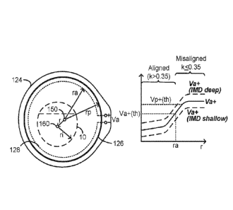
function of IMD 10 depth, but also in accordance with the power of the
magnetic field 66 that
is produced by the charging coil 126. This is important to recognize because
the charging
coil 126 and hence the power of the magnetic field 66 may be controlled and
varied in the
charging system 102 for any variety of reasons, some of which are discussed
later. Such
control will also affect Va, which may make comparison of magnitude Va+ to a
set
magnitude alignment threshold Va+(th) difficult. As such, it may be necessary
for the
position circuitry 140 to normalize the Va+ measurement with respect to the
power of the
magnetic field 66 before it is compared to the magnitude alignment threshold,
Va+(th). Such
normalization of the Va+ measurement can comprise for example dividing Va+ by
any
number of parameters that would indicate magnetic field strength. This could
include the
magnitude of the voltage across the charging coil 126 (Vcoil+), the magnitude
of the current
through the charging coil 126 (Icharge+), or inputs to the charging circuitry
64, such as a duty
cycle at which the charging circuitry 64 drives the charging coil 126, as
explained later.
Instead of normalizing the sense coil measurement Va+, the threshold, Va+(th),
could also be
normalized (e.g., by multiplying it by a parameter indicative of indicate
magnetic field
strength).
[0063] Normalization of sense coil measurements though are not strictly
necessary. For
example, the charging coil 126 may be controlled to produce a test or default
magnetic field
66 of a known constant power at times when sense coil measurements are taken
to determine
alignment, as discussed further below. Magnitude Va+ thus would not vary due
to changes in
magnetic field power at those times, allowing a magnitude alignment threshold
Va+(th) to be
chosen and applied with more confidence.
[0064] Figures 7A-7C show another example in which a single sense coil can be
used to
determine alignment. In this example, the alignment sense coil 128' comprises
an edge
detector coil, so named because the coil 128' is shaped to detect the presence
of the IMD 10
when it generally breaches an area (A) bounded by two circular concentric
pieces relative to
center 150: an inner piece of smaller diameter ral, and an outer piece of
larger diameter ra2.
Alignment sense coil 128' is circular and again is concentric with the
charging coil 126. The
inner and outer pieces are connected such that a current flowing through the
alignment sense
coil 128' will flow in different directions in the two pieces. For example,
and as shown by
the arrows in Figure 7A, a current flowing clockwise in the smaller diameter
piece (ral) will
flow counter-clockwise in the larger diameter piece (ra2). Ignoring the IMD 10
for a
moment, notice that a magnetic field 66 passing though the pieces of the
alignment sense coil
128' will induce currents in the two pieces that oppose one another because of
the manner in
16
CA 03026654 2018-12-05
WO 2017/218349
PCT/US2017/036831
which they are connected. In effect then, the total current flowing in the
alignment sense coil
128', and the resulting voltage Va that forms across it, will be proportional
to the difference
in area between the outer and inner pieces, i.e., the area A bounded between
them.
100651 Like the first single alignment sense coil 128 of Figures 6A-6C, the
radii of the inner
(ral) and outer (ra2) pieces are generally close to, but preferably smaller
than, the radius rp of
the charging coil 126. Further, radii ral and ra2 are preferably close in
value (e.g., ral
between 50% to 95% of ra2) to define a narrow area A. The average radius of
the two pieces,
and hence the alignment sense coil 128' generally, may be referred to as a
single radius ra for
simplicity. As with the alignment sense coil 128 described earlier, each of
the inner and outer
pieces of alignment sense coil 128' can be tailored in terms of their
thicknesses, lengths, and
numbers of turns, although this isn't illustrated. Again, modifying such
variables is useful to
tuning the range of Va. Alignment sense coil 128' is again preferably formed
in the traces of
circuit board 124, although that isn't strictly necessary.
[0066] When the charging coil 126 is perfectly aligned with the IMD 10 (i.e.,
when r = 0, and
centers 150 and 160 coincide), the IMD 10 doesn't eclipse the area A of the
alignment sense
coil 128'. The IMD 10 would thus have limited effect on the coupling of the
magnetic held
66 to the alignment sense coil 128', and magnitude Va+ would be near a maximum
value, as
shown in Figure 7A. As radius r increases, the IMD 10 will start to encroach
upon area A of
the alignment sense coil 128', and Va+ starts to decrease, eventually reaching
a minimum
when the IMD 10 is generally eclipsing the alignment sense coil 128- to a
maximum extent¨
i.e., when r = ra. As r increases further, the IMD 10 would eventually start
to move outside
of area A, and Va+ would increase, eventually reaching a maximum value when
the IMD 10
no longer affects coupling to the alignment sense coil 128'. Notice that
magnitude Va+ at its
maximum (high values of r) would be higher (A) than Va+ at low values (e.g., r
= 0), simply
because at low values the IMD 10 will have some small coupling to the
alignment sense coil
128'.
[0067] The minimum value of magnitude Va+ assists in choosing a magnitude
alignment
threshold Va+(th) that can be used by the position circuitry 140 when
alignment sense coil
128' is used. While the magnitude alignment threshold Va+(th) may be set to
the minimum
value of Va+, Va+(th) may also be set at a value slightly higher than this
minimum to ensure
that it is not "missed- by the position circuitry 140. Thus, and as before,
magnitude Va+ of
alignment sense coil 128' can be sensed and used to indicate misalignment by
comparison to
alignment threshold Va+(th).
[0068] Position circuitry 140 may be modified to account for the difference in
shape of the
17
CA 03026654 2018-12-05
WO 2017/218349
PCT/US2017/036831
Va+ versus radius curve of Figure 7A when determining misalignment. For
example,
position circuitry 140 may determine whether Va+ has fallen (e.g., to Va(th)),
and
subsequently starts to increase, and issue a misalignment indicator 74 at that
time. Note in
this regard that position circuitry 140 may store previous Va+ measurements as
a function of
time.
[0069] Use of the edge-detection alignment sense coil 128', and the shape of
its Va+ curve
versus radius, may allow for choosing of a magnitude alignment threshold
Va+(th) that can
accurately establish a boundary between alignment and misalignment regardless
of IMD 10
depth. Figure 7A shows two Va+ curves for deep and shallow implants. A single
Va+(th)
can be chosen that is above the minimum of Va+ for both of these extreme
cases, hence
allowing Va+ to be used to determine alignment regardless of implant depth,
and potentially
without the need to adjust Va(th) for different IMD depth conditions. That
being said,
Va+(th) can as before be adjusted for different IMD depths per USP 9,227,075
discussed
earlier. Further, either Va+ or Va+(th) can be normalized to account for the
power of the
magnetic field 66, as discussed earlier.
[0070] Figures 8A and 8B present another alignment sense coil arrangement 128"
that is
similar in function to the edge detection alignment sense coil 128' of Figures
7A-7C, but that
uses concentric circular inner and outer alignment sense coils 128_1 and 128_2
that are not
connected As in alignment sense coil 128', inner and outer alignment sense
coils 128_1 and
128_2 have radii ral and ra2 that are preferably close in value. However,
because the
alignment sense coils 128_1 and 128_2 are not connected, they will each be
induced with
individual voltages Val and Va2 that are passed to the electronics module 104
via cable 106.
As before, each of alignment sense coils 128_1 and 128_2 can be tailored in
terms of their
geometry and number of turns to achieve values for Val and Va2 that
appropriate for the
electronics module 104.
[0071] At the electronics module 104, voltages Val and Va2 can be subtracted
(or added if
the voltages are of opposite polarity), which generally equals the singular
voltage Va for the
edge detection alignment sense coil 128' of Figures 7A-7C. Thus, the magnitude
Va+ curve
again experiences a minimum as shown in Figure 8A, with an alignment threshold
Va+(th)
being established as already discussed. Processing of the sense voltages Val
and Va2 can
occur in position circuitry as before, with AID 142_1 and 142_2 used to
digitize these
voltages, and with subtraction of them occurring in the position circuitry
140. Alternatively,
both of voltages Va2 and Val can be presented to a differential amplifier 144
which can
perform the subtraction prior to digitization and presentation to the position
circuitry 140, as
18
CA 03026654 2018-12-05
WO 2017/218349
PCT/US2017/036831
shown in dotted lines. Otherwise, the position circuitry 140 for alignment
sense coil
arrangement 128 (hereinafter alignment sense coil 128 for short, even though
comprising
two sense coils 128_1 and 128_2) can function as before to determine and
indicate
misalignment. A magnitude alignment threshold Va+(th) useable by position
circuitry 140
can again be adjustable based on implant depth, and/or the position circuitry
140 can apply
normalization to account for the power of the magnetic field 66, as explained
previously.
[0072] While alignment sense coil 128" as shown comprises two alignment sense
coils
128_1 and 128_2, note that even further numbers of alignment sense coils 128_x
could be
used, such as such as three or more. The inclusion of even further numbers of
alignment
sense coils 128_x would provide further information, and allow position
circuitry 140 to
determine alignment with further precision.
[0073] To this point, alignment sense coils 128, 128', and 128" have been
described that
determine misalignment between the charging coil 126 (charging coil assembly
102 more
generally) and the IMD 10, i.e., when alignment is significantly poor such
that the charging
coil 126 and the IMD's charging coil 36 are not well coupled, and thus the
charging coil 126
in its present position is unable to adequately charge the 1MD's battery 14.
However, in
subsequent examples, charging system 100 uses one or more sense coils to
determine whether
the charging coil 126 is "centered- with respect to the IMD 10. As explained
below, a
charging coil 126 is "centered" with respect to the IMT) 10 when it is well
aligned with IMD
10, i.e., when the charging coil 126 and the 1MD's charging coil 36 are very
well coupled,
and thus the charging coil 126 is able to quickly charge the IMD's battery 14.
For example,
the charging coil 126 can be said to be centered with the IMD 10 if the
coupling value k
between them is greater than 0.65, and not centered if k is less than or equal
to 0.65, although
again this value would be application specific. A charging coil 126 can thus
be aligned (not
misaligned) with the IMD 10 even if it is not centered, e.g., if 0.35 <k
<0.65).
[0074] To detect when the charging coil assembly 102 is centered with the IMD
10, circuit
board 124 can include one or more centering sense coils 129, shown first in
Figures 9A-9C.
In the example shown, centering sense coil 129 is circular, similar to the
alignment sense coil
128 of Figures 6A-6C, but sense coil 129 could also comprise an edge detector
centering
sense coil (129') that would be similar in geometry to the edge detector
alignment sense coil
128' illustrated earlier in Figures 7A-7C. Sense coil 129 could also comprise
one or more
separate centering sense coils (129_I and 129_2; collectively 129") that would
be similar in
geometry to the alignment sense coil 128- illustrated earlier in Figures 8A
and 8B.
Centering sense coil is for simplicity subsequently referred to by element
129, even though
19
CA 03026654 2018-12-05
WO 2017/218349
PCT/US2017/036831
alternative non-illustrated geometries 129' or 129" could also be used.
100751 Like the alignment sense coils, centering sense coil 1129 is induced
with a voltage, Vc
(or Vel and Vc2 if two or more separate centering sense coils are used per
129¨). Like Va,
the maximum magnitude of Vc, Vc+ is a function of the coupling to the primary
charging
coil 126 and coupling related to the proximity of the IMD 10. Thus, magnitude
Vc+ will
drop when the IMD 10 is proximate to the area encompassed by the centering
sense coil 129.
Centering sense coil 129 may again be formed in the conductive traces of the
circuit board
124 but could also comprise wire windings, and the geometry of the sense coil
129 can be
tailored to achieve values for Vc (or Vc1 and Vc2) that can be handled by the
electronics
module 104.
[0076] Like the alignment sense coil 128, centering sense coil 129 is
preferably centered
around center 150, and comprises a radius re (or radii rd l and rc2 with an
average radius of rc
if 129' or 129¨ are used). In one example, radius rc can be approximately
equal to radius ri
of the IMD 10. As shown in the graph of magnitude Vc+ versus radius r, which
shows Vc+
for a single sense coil like that of Figure 6B earlier, Vc+ will be at a
minimum when the
charging coil 126 (charging coil assembly 102) is perfectly aligned with the
underlying IM[)
(i.e., when centers 150 and 160 coincide, and r = 0). As radius r increases,
the IMD 10
will start to breach the extent of the centering sense coil 129 almost
immediately, and thus
Vc+ will start to increase and will eventually come to a maximum value when
the IMD 10 is
no longer coupled to the centering sense coil 129. From this graph, a
magnitude centering
threshold, Vc+(th) can be chosen. Like the magnitude alignment threshold
Va+(th) discussed
earlier, Vc+(th) can be chosen in different manners. In the example shown,
Vc+(th) is
chosen to establish that the charging coil 126 is centered with respect to the
IMD 10 if the
radius r between the two is less than 1/2re. Thus, the charging coil assembly
102 will be
deemed centered to the IMD 10 so long as the center 160 of the IMD 10 is
within a small area
A' relative to the center 150 of the charging coil 126, as shown in Figure 9B.
[0077] Positioning circuitry 140 can then compare magnitude Vc+ as measured to
Vc+(th)
and issue a centering indication 75. For example, if the charging coil 126 is
not centered¨
i.e., if Vc > Vc(th)¨then a centering indicator 75 may issue, which like the
alignment
indicator 74 may comprise use of a speaker. LEDs, etc. Centering indicator 75
can alert the
patient to either a centered condition, a non-centered condition, or both.
Notice also that the
sensing circuitry for Vc (e.g., A/D converter 142) can also be the same or
similar to the
circuitry used to sense Va.
[0078] Similar to the magnitude alignment threshold Va+(th), the centering
threshold
CA 03026654 2018-12-05
WO 2017/218349
PCT/US2017/036831
Vc+(th) could also be adjusted for individual patients based upon the
particular depth of their
IMDs 10, and/or the position circuitry 140 can apply normalization to account
for the power
of the magnetic field 66, as described above.
100791 To this point, alignment (Figs. 6A-8B) and centering (Figs. 9A-9C) of
the charging
coil 126 to the IMD 10 have been discussed separately. However, there are
additional
advantages to IMD 10 charging when both techniques are used together, as shown
in Figures
10A-11B. In particular, using both techniques together allows the charging
system 100 to
determine and/or indicate three possible positions of the charging coil 126
relative to the IMD
10: centered (e.g., r < %re or k> 0.65), misaligned (e.g., r> ra or k <0.35),
and a middle
position of intermediate coupling in which the charging coil 126 is not
centered but is not
misaligned with the IMD ('rc <r < ra or 0.35 <k <0.65).
[0080] Starting with Figures 10A and 10B, the charging coil assembly 102, in
addition to
charging coil 126, includes both an alignment sense coil 128 and a centering
sense coil 129,
which can be constructed in any of the various forms described earlier. Single
coils 128 and
129 of radii ra and rc (see Figs. 6B and 9A) are illustrated for simplicity.
[0081] 'the position circuitry 140 is programmed an alignment and centenng
algorithm 180,
which is discussed further with reference to Figures 12A and 12B. The
algorithm 180
receives Va and Vc as digitized, and compares magnitudes Va+ and Vc+ to
thresholds
Va+(th) and Vc+(th) as before to determine whether the charging coil 126 is
centered,
misaligned, or not centered but not misaligned. Either or both of an alignment
indicator 74
and/or centering indicator 75 can issue accordingly. One skilled will realize
that algorithm
180 can be stored on any non-transitory computer readable media, including
solid state
memory within the control circuitry 72.
[0082] One advantage of using separate alignment 128 and centering 129 sense
coils¨or two
different concentric coils more generally _______________________ concerns
normalization of the sense coil
measurements. Va and Vc will vary with the power of the magnetic field 66
produced by the
charging coil 126, and as discussed above such measurements can be normalized
to remove
magnetic field power as a variable, and to make comparison to thresholds
Va+(th) and
Vc+(th) more reliable. However, when two or more sense coils are used, one
sense coil
measurement can be normalized using the other measurement, because that other
measurement will be generally indicative of magnetic field strength (even if
affected by IMD
coupling). For example, magnitude Va+ can be divided by magnitude Vc+ before
it is
compared to magnitude alignment threshold Va+(th), and Vc+ can be divided by
Va+ before
it is compared to centering threshold Vc+(th).
21
CA 03026654 2018-12-05
WO 2017/218349
PCT/US2017/036831
[0083] In fact, an additional sense coil can be included in the charging coil
assembly 102 and
measured merely for normalization purposes. For example, in Figure 10B, sense
coil 128 and
its measured voltage Va may not necessarily be used in an alignment
determination. Instead,
centering and/or alignment might be determined by sense coil 129 and its
voltage Vc (as
explained further with respect to Figs. 11A and 11B), with Va+ merely used to
normalize
Vc+ (e.g., Vc+Na+) before it is compared to a relevant threshold (Va+(th)
and/or Vc+(th)).
[0084] Alignment and centering can also be detected using a single sense coil.
For example,
in Figures 11A and 11B, a single alignment/centering sense coil 130 is used.
In the example
shown, alignment/centering sense coil 130 is circular, although it could
comprise an edge
detector sense coil (130') or separate centering sense coils (130_1 and 130_2;
collectively
130"), similar to those shown in Figures 7A-8B. Alignment/centering sense coil
is for
simplicity subsequently referred to by element 130, even though alternative
non-illustrated
geometries 130' or 130¨ could also be used.
[0085] The radius rx of the alignment/centering sense coil 130 is preferably
between the radii
ra and rc of individual alignment and centering coils 128 and 129 described
earlier. A
magnitude ot voltage Vx induced across the coil 130, Vx+, can be compared to
separate
magnitude thresholds Va+(th) and Vc+(th) in the alignment and centering
algorithm 180 of
the position circuitry 140. Such thresholds can be chosen to establish
boundaries for a
centered condition (within area A') and a misaligned condition (outside area
A") for the
charging coil 126 relative to the IMD 10. Such boundaries may coincide with or
be
established in light of the radii of the individual alignment and centering
coils 128 and 129
presented earlier. For example, alignment magnitude threshold Va+(th) may
establish a
radius of ra outside of which the IMD 10 is deemed misaligned (i.e., when Vx+
> Va+(th)),
while centering magnitude threshold Vc+(th) may establish a radius 'i2Vc
inside of which the
IMD is deemed centered (when Vx+ < Vc+(th)). Alignment and centering
indicators 74 and
75 can again be used to indicate centered, misaligned, and/or aligned but not
centered
conditions.
[0086] An example of alignment and centering algorithm 180 is summarized
briefly before
being explained in detail with respect to Figures 12A and 12B. The algorithm
180 requires a
patient at the beginning of an IMD charging session to first center the
charging coil 126
(charging coil assembly 102) with the underlying IMD 10 (e.g., r < 'Airy).
Thereafter and
during charging, the charging coil 126 may move, and may even move from a non-
centered
position (e.g., r> 1/2rc) so long as the charging coil 126 is still aligned
with the IMD 10 (e.g.,
r < ra). However, should the charging coil 126 move to such an extent that it
is no longer
22
CA 03026654 2018-12-05
WO 2017/218349
PCT/US2017/036831
aligned with the IMD 10 (e.g., r> ra), then the patient will be required to
once again re-center
the charging coil assembly 102 (e.g., r < 'Arc) before charging will again
commence in
earnest.
100871 Such operation of the alignment and centering algorithm 180 is
beneficial, because it
ensures, initially and later after misalignment, that the charging coil 126 is
centered with the
IMD 10, and thus that the two are very well coupled. Requiring such centered
positioning
means that the charging coil 126 is not likely to soon move out of alignment
with the IMD
10, because it would have to move an appreciable distance (from 1/2rc to ra)
to do so.
[0088] This is an improvement over previous alignment techniques in which
charger-to-IMD
positioning was merely assessed by a simple aligned/misaligned determination.
Consider for
example Figure 3, in which alignment was determined (70) by merely comparing
Vcoil of the
primary coil 52 to an alignment threshold Vt. Assume at the beginning of a
charging session
that the external charger 50 is relatively poorly aligned with the IMD 10,
perhaps because it
is significantly offset (x) as shown in Figure 4B. Assume further that the
external charger 50
is nonetheless still technically aligned, because Vcoil < Vt, although Vcoil
is also very close
to Vt. The external charger 50 could easily soon go out of alignment (Vcoil >
Vt) as the
patient moves. This provides a frustrating use model for the patient, who
believes his
external charger 50 is aligned, only to find out a short time later (perhaps
seconds later) that
alignment requires his attention Even thereafter should the patient move the
external charger
50 back into alignment with the IMD 10 (Vcoil < Vt), the charger could again
go quickly out
of alignment with the IMD if again it is on the verge of being misaligned.
[0089] The alignment and centering algorithm 180 addresses this problem,
because charging
can't commence if the charging coil assembly 102 is only barely aligned with
the IMD 10.
Instead, the charging coil assembly 102 must then be centered with the IMD 10,
in effect
requiring the very good alignment with the IMD 10 that centering provides.
[0090] Figure 12A shows alignment and centering algorithm 180 in flow chart
form, while
Figure 12B shows the magnetic field that is produced at the charging coil 126
as a result of
the algorithm. First, the patient turns on the charger system 100 (190), for
example by
pressing the on/off button 116 (Fig. 5B) on the housing 105 of the electronics
module 104. A
test or default magnetic field can then be produced from the charging coil 126
(192). As
alluded to earlier, this test magnetic field 66 may be of a known constant
power, and may be
lower in power that a true magnetic field 66 used later in the process to
operatively charge the
IMD's battery 14. Use of a low-power magnetic field is preferred to ensure
that the IMD 10
is not over-powered before the charging system 100 is able to determine
whether the charging
23
CA 03026654 2018-12-05
WO 2017/218349
PCT/US2017/036831
coil 126 is centered. A constant power test magnetic field by using a set duty
cycle with the
charging circuitry 64, as described in detail later.
[0091] The algorithm 180 may deduce as a first step whether the IMD 10 is
present (193)¨
whether the charging system 100 detects the presence of the IMD 10 such that
assessment of
position and charging can begin. Detecting the presence of the IMD 10 can
occur in any
number of ways. For example, the magnitude of the voltage formed across the
charging coil
126, Vcoil+, can be assessed during production of the test magnetic field, and
compared to a
IMD presence magnitude threshold, Vp+(th).
[0092] Alternatively, the charging system 100 may determine IMD presence using
measurements taken from any of the sense coils illustrated earlier, and used
later during the
algorithm 180 to determine charger-to-IMD alignment and/or centering. For
example, the
bottom of Figure 12A shows a graph of magnitude Va+ as measured at an
alignment sense
coil 128 (see Fig. 6B). In addition to assessment of the alignment magnitude
threshold
Va+(th) discussed earlier, Va+ may be compared to an IMD presence threshold
Vp+(th),
which may be set just below Va+'s maximum value. If Va+ > Vp+(th), then the
charging
system 100 (e.g., position circuitry 140) may determine that the 1MD 10 is not
yet within a
detectable range of the charging coil 126 (charging coil assembly 102).
Although not
illustrated, the detected presence or not of the IMD 10 may be indicated to
the user through
an alert issued by the charging system's user interface (e g, one or more of
LEDs 118a or
118b). Notice therefore that the charging system 100, in addition to
determining alignment
and misalignment, and/or centered and non-centered (conditions where the IMD
10 is present
with respect to the charging coil 126), may additionally determine that the
IMD 10 is not
present with respect to the charging coil 126.
[0093] Still other techniques can be used to determine IMD 10 presence with
respect to the
charging coil 126 at step 193. For example, the technique of USP 9,186,520 can
be used,
which technique can also be used to automatically turn on the charging system
when IMD 10
presence is detected.
[0094] Once IMD presence is determined and with the test magnetic field 66
produced, one
or more voltages are sensed to determine whether the charging coil 126 is
centered with the
IMD 10 (194). For example, magnitude Vc+ of centering sense coil 129, or Vx+
of
alignment/centering sense coil 130, perhaps as normalized in the various ways
described
earlier, can be compared to the centering threshold, Vc+(th). Initially, it
might be expected
that the charging coil 126 is not well centered, especially if the patient is
in the process of
placing the charging coil assembly 102 proximate to the IMD 10. In that case,
the patient
24
CA 03026654 2018-12-05
WO 2017/218349
PCT/US2017/036831
would be alerted (centering indication 75) that the charging coil 126 is not
centered (196) so
that he can attempt to move the charging coil assembly 102 into a better
position relative to
the IMD 10. Such alert could be in the various forms previously described. In
a particular
example, such alert could comprise illuminating an LED (e.g., 118b) on the
electronics
module 104 with a color indicative of centering/alignment status. For example,
LED 118b
might initially be lit red before the charging coil 126 is centered.
[0095] The assessment of centering (194) can be repeated at sensible
intervals, such as every
1.0 seconds or so. Once centering is achieved ___________________ for example,
when Vc+ or Vx+ < Vc(th) and
thus the radius r between the charging coil 126 and the IMD 10 is less than
lArc as discussed
in previous examples¨the previously issued non-centered alert can cease (198).
For
example, LED 118b might now be lit green to indicate that the charging coil
126 is centered.
Further, the charging coil 126 can now produce a true magnetic field 66
operable to charge
the IMD 10's battery 14 (200). Such true magnetic field 66 is likely be higher
in power than
the test magnetic field, and may also vary per normal charging coil 126
operation and control,
as shown by the arrows in Figure 12B, and as discussed further subsequently.
The true
magnetic field 66 can continue to be produced for a reasonable time period
(t1) such as 30
second or so.
[0096] Thereafter, the alignment and centering algorithm 180 will measure the
alignment of
the charging coil assembly 102 with respect to the MD 10 (202) This
measurement may
again involve use of the constant low-power test magnetic field. Preferably,
the alignment
measurement takes place quickly, for example, over a period (t2) of 1.0
seconds, and thus
doesn't significantly interrupt charging of the IMD 10 via the true magnetic
field.
Misalignment can be determined by assessing the magnitude Va+ of the sense
coil 128 or
magnitude Vx+ of alignment/centering sense coil 130, perhaps as normalized in
the various
ways described earlier.
[0097] If the charging coil 126 is not misaligned (204)¨for example if Va+ or
Vx+ is <,
Va+(th) and thus the radius r is less than ra as discussed in previous
examples¨then charging
can then continue (200), with the charging coil 126 once again producing a
true magnetic
field for another period ti. Note in this example that the charging coil 126
may no longer be
centered with the IMD 10 at this point. That is, radius r may be greater than
1/2rc but less than
ra. But in this example, that does not matter: so long as there is not a more-
significant
misalignment condition and thus the IMD 10 is still reasonably coupled to the
charging coil
126 and adequately charged by it, charging via the true magnetic field can
continue.
[0098] If the charging coil 126 is misaligned (206)¨for example if Va+ or Vx+
is > Va+(th)
CA 03026654 2018-12-05
WO 2017/218349
PCT/US2017/036831
and thus the radius r is greater than ra¨then the patient is again alerted
(alignment indicator
74), such as by lighting the LED 118b red once again. The algorithm 180 then
essentially
returns to its beginning: a test magnetic field is produced from the charging
coil (192), and
once again the patient must move the charging coil assembly 102 to center it
with the IMD 10
(e.g., r < 1/2rc) (194-198) before a true magnetic field can begin again
(200).
[0099] As just discussed, it may not matter to the alignment and charging
algorithm 180 that
the charging coil 126 eventually becomes non-centered with the IMD 10, so long
as it also
remains aligned (202-206). Normal charging of the IMD 10 can continue.
However,
optional steps in algorithm 180 shown in dotted lines can also be used to
notify the user of the
non-centered but aligned condition, even if it doesn't affect charging. If the
charging coil
126 is not misaligned (204), the algorithm 180 can nonetheless check whether
it is still
centered (208), similar to what occurs initially in step 194. If the still-
aligned charging coil
126 is still centered (210), charging can continue. In this circumstance, LED
118b can
remain green (or can be turned to green if previously lit to amber, as
explained momentarily).
However, if the still-aligned charging coil 126 is not centered (212), the
user may be alerted
of this fact, even though charging will still continue, and even if the
patient is not now
required to move the charging coil 102. For, example, LED 118b might be lit
amber in this
circumstance. In effect, these optional steps in the algorithm 180 measure
three different
conditions for the charging system, and issue three different alerts a
centered condition
(green), a non-centered but not misaligned condition (amber), and a misaligned
condition
(red).
[00100] It should be
noted that steps 202 and 208¨assessing alignment and
centering¨need not occur in the order illustrated and could be assessed
concurrently. For
example, it may be sensible to assess alignment (202) only if the charging
coil 126 has
become not centered (208).
[00101] Although the
alignment and centering algorithm 180 is described using "test"
and "true" magnetic fields 66 which may be different, this is not strictly
necessary. Instead,
the charging coil 126 may produce a single true magnetic field 66 through
operation of the
entire algorithm 180 of the type used to meaningfully provide power to the IMD
10.
Normalizing of the sense coil measurement may become more important in this
circumstance
to account for possible variations in magnetic field 66 power, as discussed
earlier.
[00102] To this
point in the disclosure, charger-to-IMD position (e.g., alignment and/or
centering) has been determined with reference to the maximum magnitude of the
voltage that
is induced on the sense coil. However, the inventors realize that other sense
coil parameters
26
CA 03026654 2018-12-05
WO 2017/218349
PCT/US2017/036831
may be used to determine charger-to-IMD positioning, in particular the phase
angle (0) of
induced voltage relative to the signal used to drive the charging coil 126,
and the resonant
frequency (f(res)) of the charger/1MD system. The inventors realize further
that use of two or
more sense coil parameters¨for example, two or more of magnitude, phase angle
(0), and
resonant frequency f(res)¨can be used to improve the positioning
determination, in
particular by allowing charger-to-IMD depth (d) to be determined as well as
charger-to-IMD
radius (r). Before discussing such concepts in detail, further details of the
circuitry in the
charger system 100 are discussed with reference to Figures 13A-13C.
[00103] Figure 13A shows further details regarding the charging circuitry
64 used to
energize the charging coil 126 with AC current, Icharge. A digital drive
signal D is formed
by a square wave generator 65, which may comprise a part of the control
circuitry 72. Drive
signal D comprises a pulse-width modulated (PWM) signal with a periodically-
repeating
portion that is high (logic '1') for a time portion `a- and low for a time
portion `b.. As such,
the drive signal D has a duty cycle DC equal to a/(a+b). Further, the drive
signal D has a
frequency f equal to 1/(a+b). The frequency f of the drive signal is generally
set to or near
the resonant frequency of the capacitor 131/charging coil 126 LC circuit
(e.g., around 80
kHz), although the frequency of the drive signal can also be adjusted, as
explained
subsequently.
[00104] Charging el i try 64 can comprise a well-known H-bridge configurati
including two N-channel transistors coupled to a power supply voltage Vcc, and
two P-
channel transistors coupled to a reference potential such as ground (GND). The
transistors
are driven on and off by the drive signal D and its logical complement D*. In
so doing, the
power supply voltage Vcc and ground are made to alternate across the LC
circuit t frequency
f, thus producing the magnetic charging field 66 at this frequency. Power
supply voltage Vcc
may comprise the voltage of the battery 110 (Fig. 5A) in the electronics
module 104, or may
be regulated from that voltage. As is well known, the duty cycle DC of the
drive signal D
can be increased from 0 to 50% to increase Icharge, thus setting the power at
which the
charging coil 126 is energized and hence the power of the resulting magnetic
field 66.
[00105] The AC voltage Vy (e.g., any of Va, Vc, or Vx introduced earlier)
induced
across the sense coil 178 (e.g., any of 128, 128', 128", 129, 129', 129", 130,
130' or 130"
introduced earlier) will also have a frequency equal to f, but may be shifted
in phase angle (0)
relative to the drive signal D (and hence relative to the voltage Vcoil across
the charging coil
126 and the magnetic field 66). This is shown in Figure 13B, in which phase
angle 0 is
measured as the difference between the center of the drive signal D (top
portion 'a') and
27
CA 03026654 2018-12-05
WO 2017/218349
PCT/US2017/036831
where Vy = 0. However, this is arbitrary, and phase angle 0 of sense coil
voltage Vy can be
determined with respect to different reference points, or with respect to
Vcoil or the magnetic
field 66.
[00106] Sense coil
voltage Vy is digitized at AID 142 as mentioned earlier, and is
sampled at a frequency, Fs. As shown, the digitized samples are provided to Vy
magnitude
and phase angle determination module 170, which may operate as firmware within
the
position circuitry 140 and within control circuitry 72 more generally. Module
170 is capable
of concurrently determining both the magnitude of Vy (Vy+) and the phase angle
(0) by
assessing N digitized samples of Vy. Figure 13C explains the mathematics
involved.
Essentially, each of the samples (VyN) is multiplied by orthogonal
trigonometric functions
(sin(co x tN) or cos(o) x tN)), added together, and normalized by the number
of samples (1/N),
rendering values I and R. The magnitude of Vy (Vy+) and phase angle (0) are
then
determined as a function of I and R as shown in the equations at the right.
Note that
magnitude Vy+ determined in this manner comprises a zero-to-peak value of Vy,
as shown in
Figure 13B.
[00107] Magnitude
Vy+ and phase angle 0 could also be determined in different
manners as one skilled will understand, and need not be determined
concurrently in the same
module or circuitry. For example, magnitude Vy+ can be determined by
rectifying Vy to a
DC voltage for example using a full wave rectifier Phase angle 0 can also he
determined
using analog components. Figure 13D for example shows that the phase angle
between Vy
and drive signal D can be determined using a phase comparator 182, which as is
known
outputs a voltage (Vcntr) that is indicative of the phase angle 0. If
necessary, sensed voltage
Vy can be limited (clipped) and level shifted into a digital signal that is
more easily compared
to the digital drive signal D at the phase detector 182.
[00108] It should be
noted that the number of samples of Vy (N) and the frequency at
which such samples are taken (Fs) can vary depending on the desired accuracy
Vy+ and 0,
and how long the measurement should take.
[00109] Another
sense coil parameter that may be assessed to determine charger-to-
IMD positioning is the resonant frequency, f(res), of the charger-1MD system.
The resonant
frequency f(res) can be determined in a resonant frequency determination
module 172 (Fig.
13A) within the position circuitry 140, which also can be operable as
firmware. Module 172
may use the phase angle 0 determined in module 170 to assist in determining
the resonant
frequency, f(res). Specifically, module 172 may vary the frequency f of the
drive signal D
until the phase angle 0 received from module 170 equals 0, thus establishing
f(res) at that
28
CA 03026654 2018-12-05
WO 2017/218349
PCT/US2017/036831
frequency f. Such varying of the frequency can be an iterative process, and
may require
several adjustments to the frequency of the drive signal D. How the frequency
is adjusted
may involve consideration of the polarity of the phase angle 0. For example,
module 172
may lower the frequency f if the phase angle is positive and raise it if the
phase angle is
negative.
[00110] Frequency
adjustment to the drive signal D to determine resonant frequency
f(res) may occur by varying either or both of time portions 'a' and 'b' at the
square wave
generator 65. In one example, both of time portions 'a' and 'b' may be equally
scaled, thus
keeping the duty cycle DC of the drive signal D constant, and thus keeping the
power of the
charging coil 126 and magnetic field 66 constant. However, this is not
strictly necessary, as
variations in duty cycle and power resulting from small frequency adjustments
may be
negligible or permissible. Thus, only portions 'a' or 'b' may be varied.
[00111] Measuring
f(res) of the charger-IMD system may also be accomplished using
analog circuitry. Referring again to Figure 13D, the determined phase angle
(expressed as
Vcntr) may be compared to a reference voltage (Vref) at a comparator 186. Vref
may be set
to equal V cntr when the phase angle is zero degrees, and thus the comparator
may output a
digital signal to the square wave generator 65 indicating whether the phase
angle is higher
('1') or lower (0') than zero degrees. The square wave generator 65 in turn
may thus
increase or decrease the frequency of the drive signal D, which is provided
hack to the phase
comparator 182 via feedback loop 190 until Vcntr = Vref and phase angle 0
equal zero, at
which point f(res) is determined as the frequency f to which the drive signal
D has been
adjusted. Still other analog feedback circuits could be used as well, such as
phase- or delay-
locked loops.
[00112] Figure 14A
shows experimental results of how the parameters of magnitude
Vy+ (upper left), phase angle 0 (upper right), and resonant frequency f(res)
(lower left) as
measured from the sense coil 178 vary as a function of radial offset r and
depth d between
centers 150 and 160 of the charging coil 126 and the IMD 10 respectively.
Figure 14B shows
this same data, but graphed for each sense coil parameter at a constant depth
(d = 10 mm),
which represents a typical depth at which the charging coil assembly 102 and
the IMD 10
would be separated when the IMD 10 is implanted in a patient. In this
experiment, the radius
rp of the charging coil 126 was about 30 mm, and the radius of the sense coil
178 (in this
example, a circle; see, e.g. Fig. 11B) was about 15-20 mm.
[00113] Figure 14B
verifies that any of sense coil parameters magnitude Vy+, phase
angle 0, or resonant frequency f(res) can be measured and assessed alone to
determine
29
CA 03026654 2018-12-05
WO 2017/218349
PCT/US2017/036831
charger-to-IMD positioning¨such as alignment or centering as discussed
earlier. For
example, and as discussed earlier with reference to Figure 6B for example, a
magnitude
threshold Vy+(th) can be stored in a database 200 associated with position
circuitry 140 (Fig.
13A) and compared to magnitude Vy+ as measured (module 170) to determine
charging coil
126 positioning. As the data shows, a magnitude threshold Vy+(th) = 0.18 V
establishes a
charger-to-IMD radius r of about 27 mm at the indicated depth (d = 10 mm),
which is close to
the radius to the charging coil 126 (about 30 mm). This threshold thus would
work as a good
determiner of charger-to-IMD alignment, such that if Vy+ < Vy+(th), the
charging coil 126
would be deemed aligned with the IMD 10, and misaligned if Vy+ > Vy+(th). A
different
threshold could also be stored and applied to determine a more-exacting
centered position,
such as Vy+(th') = 0.14 V, which would define the charging coil 126 as
centered when the
charging coil 126 is at or below a tighter 20 mm radius with respect to the
IMD 10.
Depending on the comparison to the one or more magnitude thresholds, the IMD
position
circuitry 140 may indicate (74, 75) the determined position to the user, such
as whether the
charging coil 126 is centered, not centered but not misaligned, or misaligned
to the user, as
explained earlier. As discussed earlier (Figs. 10A and 1013), more than one
sense coil 178
concentric with the charging coil 126 may also be used.
[00114] The measured
resonant frequency f(res) alone can be also used to determine
charger-to-IMD positioning As shown in Figure 14B, a resonant frequency
threshold
f(res)(th) = 81.2 kHz establishes a charger-to-IMD radius r of about 27.5 mm
at the indicated
depth (d = 10 mm), which again would work as a good determiner of charger-to-
IMD
alignment: if f(res) > f(res)(th), the charger coil 126 would be deemed
aligned with the IMD
10, and misaligned if f(res) < f(res)(th). A different threshold could again
be applied to
determine a more-exacting centered position, such as f(res)(th') = 81.4 kHz,
which would
define a tighter 20 mm centering radius, although this additional threshold is
not shown in
Figure 14B. Again, the resonant frequency f(res) as measured from more than
one sense coil
178 may also be used.
[00115] The measured
phase angle 0 alone can also be used to determine charger-to-
IMD positioning. Notice from the data in Figure 14B that the phase angle 0
measured from
the sense coil 178 lags the drive signal D significantly (10 ) when r = 0, and
falls off at higher
radii, eventually approaching zero degrees nearer to the radius of the
charging coil 126 (30
mm). A phase angle threshold 0(th) of about 0.8 degrees again works as a
suitable alignment
threshold for the geometry of the charging coil 126 in question and at the
indicated depth.
Again, and although not shown, an additional phase angle threshold could be
used to
CA 03026654 2018-12-05
WO 2017/218349
PCT/US2017/036831
determine centering, and phase angles can be measured from more than one sense
coil 178.
[00116] Referring
again to Figure 13A, the various thresholds just described (Vy+(th),
0 (th), and f(res)(th)) can be stored in database 200 and compared to measured
values, as may
the three-dimensional data represented in Figure 14A (Vy(r,d)), 0(r,d),
f(res)(r,d)).
Additionally, the depth d between the charging coil 126 and the IMD 10, which
again may
vary from patient to patient, may also be stored. A priori knowledge of depth
d may allow
the sense coil parameter thresholds to be determined with further accuracy.
This can be
important, because, as the contours in Figure 14A show, the measured
parameters can vary as
a function of IMD 10 depth d, meaning that a single threshold value may not be
suitable to
determine position (alignment and centering) for all depths.
[00117] If the three-
dimensional data of Figure 14A is present, and the depth d is
known, an appropriate threshold value for each sense coil parameter can be
determined from
(e.g., looked up in) database 200. For example, if it is known that the
charger-to-IMD depth
is 15 mm, and that misalignment should be indicated when the radius r exceeds
31 mm, then
a suitable resonant frequency threshold f(res)(th) would be about 80.9 kHz, as
shown by the
dotted lines an the resonant frequency data of Figure 14A. Charger-to-IMD
depth d may also
be calculated or learned and then stored in database 200, allowing appropriate
thresholds to
be chosen, using for example the technique of USP 9,227,075, which technique
is not
described here
[00118] Variation of
measured sense coil parameters with depth notwithstanding, use
of phase angle 0 to determine charger-to-IMD positioning is particularly
promising because
of its relative insensitivity to depth d. Referring again to Figure 14A, note
that the contour
for the previously chosen threshold 0(th) = 0.8 is relatively vertical,
particularly at lower
depths (d < 15 mm). This means that this phase angle threshold 0(th) will work
well to
determine alignment over a large depth, i.e., from 0 < d < 15 mm. Within this
depth range,
the error in the established misalignment radius, e, varies only slightly from
about 25-28mm,
which can be tolerable.
[00119]
Consideration by the IMD position circuitry 140 of more than one measured
sense coil parameter can also allow for a determination of both the radius r
and depth d
between the charging coil 126 and the IMD 10, particularly if the database 200
includes the
three-dimensional data of Figure 14A. Assume for example that module 170
determines the
magnitude of Vy, Vy+, to be 0.14 V. As the contour in Figure 14A demonstrates,
it cannot
be known whether the charging coil 126 is for example at position X1 or X2
based on Vy+
alone. However, if module 170 further determines that the phase angle 0 is 4.0
, then
31
CA 03026654 2018-12-05
WO 2017/218349
PCT/US2017/036831
position module 140 can determine (using Vy+(r,d) and 0(r,d)) that the
charging coil 126
must be located at position X1 , that is at about r = 17 mm and d = 10 mm
relative to IMD 10
(as measured relative to their centers 160 and 150).
[00120] In another
example, assume that module 170 determines Vy+ to be 0.30 V.
As the contour in Figure 14A demonstrates, it cannot be known whether the
charging coil 126
is for example at position YI or Y2. However, if module 172 further determines
that the
resonant frequency is 80.9 kHz, then position module 140 can determine (using
Vy+(r,d) and
0(r,d)) that the charging coil 126 must be located at position Yl, that is, at
about r = 28 and d
= 18 mm relative to IMD. Consideration of a third measured sense coil
parameter (phase
angle) can improve position determination accuracy, or verify determined
position results.
[00121] Because
depth d should remain relative constant for a patient, it may not
always be strictly necessary for the charging system to compute the depth,
especially
considering that the depth can be learned using the disclosed technique. For
example,
consideration of more than sense coil parameter can determine radius r and
depth d at
different points in time during a charging session (t2; Fig. 12B), or as the
patient uses the
charging system 100 at different times. "the depths at each of these
measurement points can
be stored in database 200, and should generally not vary. Hence, the
determined depth may
eventually be averaged from these various measurements, and then simply stored
in the
database 200 and used without having to determine it each time sense coil
measurements are
taken.
[00122] Knowing
where the charging coil 126 is relative to the IMD 10 in terms of
both radius r and depth d is useful. As discussed earlier, depth d is usually
fixed by the depth
at which the IMD 10 is implanted in the patient, because the charging coil
assembly 102 is
normally pressed against the patient. The patient thus may be unable to do
anything to adjust
the depth. By contrast, the radius between the charging coil 126 and the IMD
10 is
something the patient can adjust by laterally (radially) adjusting the
position of the charging
coil assembly 102 relative to the IMD 10. Thus, the IMD position circuitry 140
preferably
adjusts the threshold(s) per IMD depth. For example, and referring to the
f(res) contours in
Figure 14A, if alignment radius is defined as r = 32 mm, the alignment
threshold for the
resonant frequency, f(res)(th), would be set to about 81.4 kHz if the depth is
d = 5 mm; 81.1
kHz if the depth is d = 10 mm; 80.9 kHz if the depth is d = 15 mm, etc. The
position
indicator (e.g., 74) would then only indicate position (in this case
misalignment) when f(res)
as measured is lower than the depth-appropriate threshold. Similar adjustment
of the position
thresholds for magnitude Vy+ and phase angle 0 based on depth could be
similarly
32
CA 03026654 2018-12-05
WO 2017/218349
PCT/US2017/036831
determined.
[00123]
Determination and indication of positioning can also occur by assessment of
more than one sense coil parameter, and comparison of more than one threshold.
For
example, and again referring to the contours of Figures 14A, misalignment
might be
indicated if, at depth d = 10 mm, f(res) < 81.1 kHz and if Vy+ > 0.23 V, a
point indicated as
Z at an alignment radius of r = 32 mm. The phase angle could also be measured
and
considered, with misalignment indicated or confirmed if 0 < 0(th) = 0.10
.
[00124] While the
alignment and centering algorithm 180 described earlier with
respect to Figures 12A and 12B focused on use of the magnitude of the voltage
of the sense
coil (Vy+), it should be noted that the algorithm 180 works equally well the
sense coil
parameters of phase angle 0 or resonant frequency f(res) are used as well.
Thus, either of
these other sense coil parameters could be measured and compared to
appropriate thresholds
(steps 194, 202, 208 of algorithm 180) to determine whether the charging coil
126 is
centered, aligned but not centered, or misaligned. Further, these same steps
may also
measure and assess more than one of sense coil parameters Vy+, 0, and f(res),
which as just
explained can improve the accuracy of the charger-to-IMD position
determination.
[00125] The sense
coil parameters of phase angle 0 and resonant frequency f(res) are
less affected by the power of the magnetic field 66 provided by the charging
coil 126 during
the measurement (unlike voltage magnitude Vy+, which would scale with magnetic
field
power). As such, normalization of these measurements may be unnecessary, and
as such it
may be unnecessary to use a constant, lower-power test magnetic field during
those
measurements. In other words, if 0 and f(res) are used as the measured sense
coil parameters
in algorithm 180, the true (possibly varying) magnetic field may be used
during the
measurements (e.g., during t2), and the test magnetic field can be dispensed
with.
[00126] One of more
of sense coil parameters Vy+, 0, and f(res) can also be used to
adjust the power of the magnetic field 66 delivered to the IMD 10. This is
useful because
non-ideal coupling between the charging coil 126 and the IMD 10 caused by
imperfect
charger-to-IMD positioning may be remediable by increasing the power of the
magnetic field
66 provided to the IMD 10. In other words, if the coupling is low because of
charger-to-IMD
positioning, the power of the magnetic field is increased to ensure that the
IMD 10 receives
the same amount of power no matter the coupling.
[00127] Power
control is discussed further with respect to Figure 15A, which shows
further details concerning power circuitry 145 useable in the charging system.
As with
position circuitry 140 described earlier, power circuitry 145 can operate as
firmware
33
CA 03026654 2018-12-05
WO 2017/218349
PCT/US2017/036831
comprising control circuitry 72, although this is not strictly necessary as
analog circuitry can
be used for certain aspects as well. Control circuitry 72 may again contain Vy
magnitude and
phase angle determination module 170, resonant frequency determination module
172, and
database 200, and in Figure 15A those modules have been moved out from
position circuitry
140 and instead are common to (provide data to) both of position circuitry 140
and power
circuitry 145.
[00128] In one
example, data regarding the position of the charging coil 126 with
respect to the IMD 10 ___________________________________________ at least the
radius r, and preferably also depth d is provided to
power circuitry 145. As explained earlier (Fig. 14A), both r and d can be
determined by
assessing two or more of the sense coil parameters of Vy+, 0, and f(res).
However, and also
as earlier explained, depth d can be programmed into the control circuitry 72
and/or learned.
[00129] Power
circuitry 145 can assess radius r and depth d to determine an
appropriate power for the magnetic field 66. As explained earlier, magnetic
field power can
set by setting the duty cycle DC of the drive signal D, because increasing the
duty cycle DC
will increase Icharge flowing through the charging coil 126. However,
increasing drive
signal duty cycle is merely one way of increasing magnetic field power and
other ways can
also be used, depending on the charging circuitry 64 that is used to energize
the charging coil
126.
[00130] A look up
table 146 may he stored in a memory within or accessible to the
power circuitry 145, which is used to set a duty cycle DC for the square wave
generator 65
and the charging circuitry 64 depending on the radius and depth of the
charging coil 126
relative to the IMD 10. For example, if the radius and depth are both
relatively small (rl, d1),
the charging coil 126 and IMD 10 would be relatively well coupled. Thus, more
of the
magnetic field 66 generated at the charging coil 126 would reach the IMD 10,
and as a result
the duty cycle can be relatively small (DC1) for this position. By contrast,
if either or both of
the radius and depth are larger (e.g., r2, d2), coupling would be poorer.
Thus, power circuitry
145 would direct the square wave generator 65 to increase the duty cycle
(e.g., to DC3) to
ensure that the IMD 10 is receiving an adequate amount of power. As noted
above, it is
preferable that the IMD 10 receive a constant amount of power, regardless of
charger-to-IMD
positioning.
[00131] Determining
the amount of power the IMD 10 receives can be experimentally
determined in various manners by measure various parameters in the IMD 10. In
one
example, the received power can be assessed as the amount of charging current,
lbat (Fig.
15A), the IMD 10's battery 14 receives. One skilled will appreciate that as
coupling drops
34
CA 03026654 2018-12-05
WO 2017/218349
PCT/US2017/036831
(i.e., as r or d increases), Ibat would also drop if magnetic field power were
not adjusted.
This is shown in Figure 15B, which shows the power that IMD 10 receives (Ibat)
as a
function of radius and depth when the charging coil 126 produces a magnetic
field 66 of a
constant power (i.e., when Icharge and duty cycle DC are constant).
Specifically, Figure 15B
shows various regions for Ibat as derived from experimentation. As shown,
lower values for
Ibat (e.g., between Ibatl and Ibat2) are associated with poor coupling, and a
position region
having higher values for radius r and/or depth d. To compensate, this position
region is
provided with a high duty cycle (DC5), and thus a higher magnetic field power,
in look up
table 146. By contrast, higher values for Ibat (e.g., > Ibat5) are associated
with high
coupling, and a position region having lower values for radius r and/or depth
d. To
compensate, this position region is provided with a low duty cycle (DC1), and
thus a lower
magnetic field power, in look up table 146. Preferably the duty cycle
associated with each
position region will cause Ibat in the IMD 10 to be relatively constant, and
hence independent
of charger-to-IMD position. Alternatively, the duty cycle chosen (power) may
not render a
constant Ibat for all potential positions of the charging coil 126 relative to
the IMD 10, but
will at least result in a value for 'bat that doesn't drop below a minimum
value, thus ensuring
that the IMD 10 receives an adequate amount of power regardless of charger-to-
IMD
position.
[00132] While it is
preferred that the power circuitry 145 determine an appropriate
adjustments to the power of magnetic field 66 using knowledge of both radius
and depth (as
determined using sense coil parameters Vy+, 0, and/or f(res)), this is not
strictly necessary.
Instead, power circuitry 145 may instead receive the sense coil parameters
Vy+, 0, and/or
f(res) themselves and adjust the power, without determining radius and depth
as an
intermediate step.
[00133] In one
example, adjustment to the power of the magnetic field 66 occurs using
sense coil measurements taken during the issuance of test or default magnetic
field from the
charging coil 126, as was discussed earlier in conjunction with Figure 12B. In
this example,
one or more of sense coil parameters Vy+, 0, and/or f(res) are periodically
measured during
the test magnetic field (e.g., during times t1)¨and with the calculated power
(e.g., duty cycle
DC) used during the subsequent true magnetic field period (t2). In this way,
adjustments to
magnetic field power are made every 30 seconds or so using the examples for ti
and t2
provided earlier, which reasonably accommodates the time scale that the
charging coil
assembly 102 would be expected to move. Of course, this is not strictly
necessary. Further,
although not shown in Figure 12B, additional sense coil parameters
measurements could be
CA 03026654 2018-12-05
WO 2017/218349
PCT/US2017/036831
taken (during time periods 12) specifically for the purpose of magnetic field
power
adjustment. Thus, there can be different time periods at which sense coil
parameters
measurements are taken for the purpose of determining charger-to-1MD
positioning, and for
the purpose of magnetic field power adjustment.
[00134] Similar to
what was discussed earlier in conjunction with Figure 12B, sense
coil parameter measurements for the purpose of magnetic field power adjustment
need not be
taken using the low-powered test magnetic field, but could simply use the true
magnetic field
operative to charge the IMD 10. As was discussed earlier, this may make
normalizing the
measurements to the current power of the magnetic field more important,
particularly the
voltage magnitude Vy+ measurements, but less so for the phase angle 0 and the
resonant
frequency f(res) measurements.
[00135] Adjustment
of the power of the magnetic field using power circuitry 145 can
also occur as a function of the determined charger-to-IMD position. For
example, power
circuitry 145 may only be enabled to adjust the power if the position
circuitry 140 determines
that the charging coil 126 is aligned with the IMD 10. In this regard, and as
shown in Figure
15A, position circuitry 140 may communicate the status ot alignment via signal
147 to the
power circuitry 145.
[00136] The
inventors realize further that it is beneficial during the provision of power
to the IMD 10 to provide a true magnetic field 66 that is optimized nt the
resonant frequency
of the charger/IMD system¨that is, a magnetic field optimized in frequency
given the
mutual inductance provided by the coupled charger/IMD system. Providing power
at the
resonant frequency means that more of the power of the magnetic field 66 will
reach the IMD
and thus used to charge the IMD 10's battery 14. Further, providing power at
the resonant
frequency increases the signal induced on the sense coil (Vy), thus making it
easier to deduce
magnitude Vy+, phase angle 0, and resonant frequency f(res). Note that this
use of resonant
frequency is different from the purpose described earlier: while f(res) can be
measured during
test periods (12) and used to determine charger to IMD positioning and/or how
to adjust
magnetic field power (e.g., by duty cycle adjustment), here we refer to
adjustment of the
frequency of the magnetic field 66 during the provision of a true magnetic
field.
[00137] Fortunately,
providing power during a true magnetic field can use the same
circuitry described earlier to measure f(res) as useful for position
determinations and power
adjustment. For example, during a measurement period (12; see Fig. 12B), it
may be
determined that the resonant frequency of the charger/IMD system is f(res). As
described
earlier, this f(res) measurement can be used to determine and indicate (74,
75) IMD-to-
36
CA 03026654 2018-12-05
WO 2017/218349
PCT/US2017/036831
charger position, and to adjust the power of the subsequent true magnetic
field (ti), for
example, by varying the duty cycle DC of the drive signal D applied to
charging circuitry 64.
[00138] Further, the
frequency of the drive signal may independently be set to (or
allowed to continue to remain at) f(res) for the subsequent true magnetic
field period (ti) to
ensure efficiency delivery of power to the IMD 10. Notice that this adjustment
to the
frequency of the magnetic field 66 can be independent of adjustment to its
power. As
described earlier, the drive signal D has a duty cycle (power) equal to a/a+b,
while its
frequency is 1/a+b. Thus, while f(res) is governed by a+b, 'a' can still be
varied
independently within the period of the drive signal to set the duty cycle DC.
[00139] As with
power adjustment, it may be reasonable to measure f(res) during test
periods (t2), and to set f = f(res) during the subsequent during the
subsequent true magnetic
field period (t2). In this way, adjustments to the frequency to match the
resonance of the
charger/IMD system are made every 30 seconds or so (for example). However, the
frequency
of the drive signal D¨and hence the frequency of the magnetic field¨could also
be adjusted
on a different time scale, or adjusted pseudo continuously by continuously
sampling sense
coil voltage (and determining t(res) during production of the true magnetic
field.
[00140] While the
disclosed IMD position and power adjustment techniques are
described in the context of a charger system 100 having a separate electronics
module 104
and charging coil assembly 102 (see Figs SA and 511), this is not necessary
Instead, the
described techniques can also be implemented in an integrated external charger
in which
electronics, charging coil, and one or more sense coils are housed together.
For example,
Figure 16 shows such an integrated external charger 50' with all components
housed in a
single housing 62, which is generally similar to that described earlier in
Figure 2 Charger
50' includes a circuit board 54 that carries a primary charging coil 52
winding. The traces of
the circuit board 54 can include one or more sense coils 178 formed in any of
the various
marmers described. Control circuitry 72' can be programmed with position
circuitry 140,
power circuitry 145, and other supporting circuitry and programs, all of which
were
explained in detail above. Thus, it is not important to the disclosed
technique that the
charging/sense coils be separate from the electronics, or that they be housed
in separate
housings.
[00141] To this
point, the disclosed sense coils can deduce charger-to-IMD position
(e.g., centered and/or aligned), but lack the ability to deduce a direction by
which the
charging coil assembly 102 may be non-centered or misaligned. Nonetheless, the
sense coils
in charging system 100 can be modified to provide an indication to the patient
a direction of
37
CA 03026654 2018-12-05
WO 2017/218349
PCT/1JS2017/036831
misalignment or a non-centered condition.
1001421 For example,
Figure 17A includes two alignment sense coils 178a and 178b
across which voltages Vya and Vyb can be induced. In the example shown, the
alignment
sense coils 178a and 178b comprise edge detection coils of the type disclosed
earlier with
respect to Figures 7A-7C, but this is not strictly necessary. Further, the two
illustrated coils
178a and 178b could operate as centering sense coils, like coils 129 of
Figures 9A-9C, or as
combined alignment/centering sense coils, like coils 130 of Figures 11A and
11B. Further, a
pair of alignment sense coils and a pair of centering sense coils could be
used, similar to that
shown in Figure 10A and 10B. These alternatives aren't illustrated for
simplicity.
[00143] It is seen
in Figure 17A that sense coils 178a and 178b each cover roughly half
of the circumference of the PCB 124, as shown by areas A and B. If the
charging coil
assembly 102 (charging coil 126) shifts such that the IMD 10 (not shown)
eclipses area A of
sense coils 178a, then the magnitude Vya+ will drop. The control circuitry 72
in the
electronics module 104 would thus understand that the charging coil assembly
102 should be
moved downwards to be in better alignment (or better centered) with the IMD
10. Likewise,
it the 1MD 10 eclipses area B of sense coil 178b, then magnitude Vyb+ will
drop, indicating
that the charging coil assembly 102 should be moved upwards. The direction of
misalignment or non-centered, or more preferably the direction of movement
necessary to fix
alignment or centering, can he indicated by the electronics modules user
interface, and I TSP
8,473,066 discusses various means of indication, including direction-
indicating LEDs that
can be illuminated on the housing 105. The sense coil parameters of phase
angle 0 and
resonant frequency f(res) could also be measured from each of sense coils 178a
and 178b to
assist determining directional charger-to-IMD positioning, and magnetic field
power
adjustment.
[00144] Figure 17B
is similar to Figure 17A, but increases the areas A and B
encompassed by alignment (or sense) coils 178a and 178b, with each coil
essentially covering
a semicircle. In this example, induced Noltages Vya and Vyb can both be used
to determine a
misalignment or non-centered direction. For example, if Vya+ drops relatively
far in value
from its maximum value, while Vyb+ only drops a small amount, that would
indicate that the
IMD 10 is eclipsing are A to a great extent, but eclipsing area B to only a
small extent. Thus,
the charging system 100 could indicate in this example that the charging coil
assembly should
be moved upward to better align or center the assembly with the IMD. Again,
phase angle 0
and resonant frequency f(res) could also be measured from each of sense coils
178a and 178b
in Figure 14B, and used for magnetic field power adjustment. Note that due to
the non-
38
CA 03026654 2018-12-05
WO 2017/218349
PCT/US2017/036831
arcuate nature of areas A and B encompassed by the sense coils 178a and 178b,
and unlike
earlier examples of sense coils, sense coils 178a and 178b are not concentric
with the
charging coil 126.
[00145] Figure 17C
is similar to Figure 17B, but connects the two sense coils together
to form a single differential sense coil 178, sometimes referred to as a
butterfly coil. In this
instance, the direction of misalignment or non-centering would be indicated by
the relative
polarity of induced voltage Vy. If Vy is significantly negative, the IMD 10
would largely be
eclipsing area A, while if Vy is significantly positive, it would largely be
eclipsing area B. If
Vy = 0, this would indicate that the charging coil 126 and IMD 10 are
perfectly aligned.
Phase angle 0 and resonant frequency f(res) can also be measured from sense
coil 178 in
Figure 14C, with phase angle being particularly useful in determining the
polarity of Vy.
Sense coil 178 is also not concentric with the charger coil 126.
[00146] Figure 17D
includes sense coils 178a-d that are similar to those in Figure 17A,
but there are more than two, with each covering roughly a quarter of the
circumference of the
circuit board 124, as shown by areas A-D. This provides directionality
information along
orthogonal axes (along X and Y directions), thus allowing the charging system
to not only
determine whether the charging coil 126 is misaligned or not centered in the
up/down
direction, but in a left/right direction as well.
[00147] Figure 17F,
shows another example in which sense coils can he used in
charging system 100 to deduce a direction of misalignment or a non-centered
condition. In
Figure 17E, the charging coil 126 is generally elongated (more specifically,
rectangular in
shape as shown), and has a long dimension X that is significantly longer than
its other
orthogonal dimension Y. Also included within the charging coil 128 (e.g.,
within PCB 124)
are sense coils 178a and 178b, which likewise have a long X dimension and a
significantly
shorter Y dimension. Two sense coils are shown, but there could be three or
more.
Dimension X is preferably significantly larger than the IMD 10. As a result,
alignment
between the charging coil 126 and the IMD 10 in the X direction is generally
not of concern,
as it would be expected that the IMD 10 would be well within the X dimension.
However,
alignment in the smaller Y direction could still be of concern, and so sense
coils 178a and
178b are used to determine misalignment in the Y direction, which can be
accomplished by
monitoring Vya and Vyb as explained above. Again, any one or more of
magnitude, phase
angle, andtor resonant frequency could be gleaned from Vya and/or Vyb to
assist in
determining alignment in the Y direction. The sense coils 178a and 178b,
although separate
as in Figure 17B, can also be connected together to form a single sense coil
as in Figure 17C
39
CA 03026654 2018-12-05
WO 2017/218349
PCT/US2017/036831
if desired. Note that a charging coil 126 and sense coils 178 of the shape
shown in Figure
17E can be used in a generally linear-shaped charging system, such as that
used with or in a
charging belt, as mentioned earlier. Using such a charging belt, a patient
would generally
not have to worry around alignment of the belt around his waist (X: in an SCS
application),
but would instead only need to worry about adjusting the belt higher or lower
on his waist
(Y).
[00148] To this
point, what has been assessed from the various disclosed sense coils
has been a Voltage (e.g.. Va, Vc, Vx, Vy). However, sense coil current could
be assessed as
well, with current magnitude, phase, or resonance being used in the disclosed
alignment and
power adjustment techniques.
[00149] Still other
variations are possible to charging system 100. Figure 18 for
example shows that the one or more sense coils 178 in the charging coil
assembly 102 need
not merely be passive devices to sense magnetic fields, may also be actively
energized to
produce their own magnetic fields to assist with alignment and/or power
adjustment. As
shown, sense coil drive circuitry 65 has been added to the electronics module
104, which in
this example produces an AC current, Isense, dnven to sense coil 178. Any of
the sense coils
disclosed earlier could be used in this example. The frequency of Isense may
equal the
resonant frequency at which the charging coil 126 is driven, although this
isn't strictly
necessary- The frequency of Isense may he tuned in accordance with a capacitor
131 coupled
to the sense coil. This capacitor 131 is shown in parallel with the sense
coil, but could also
be placed in series.
[00150] The one or
more sense coils 178 may be driven with Isense during periods
when the charging coil 126 is also being driven with Icharge, but preferably
would be driven
during short testing periods (t2) when charging coil 126 is not energized (a)
(see Fig. 12B).
As sense coil is driven, a magnetic field 67 is formed. A voltage Vsense will
build up across
the sense coil 178, which voltage as before will be affected by coupling to
both the charging
coil 126 and the position of the IMD 10 relative to the sense coil. As before,
Vsense will be
smaller if the IMD 10 is bounded by the sense coil 178, and larger if the IMD
is not bounded
by the sense coil. Thus, Vsense may again be compared to one or more threshold
to
determine alignment, centering, and/or presence of the IMD 10, and may
additionally be used
to adjust the power of the magnetic field 66 generated by the charging coil
126, consistent
with the principles explained earlier.
[00151] Figure 19
show another variation of charging system 100 in which telemetered
feedback from the IMD 10 is used to assist with charger-to-IMD positioning
and/or magnetic
CA 03026654 2018-12-05
WO 2017/218349
PCT/US2017/036831
field power adjustment. In this example, a parameter indicative of the
coupling between the
primary charging coil 126 in the charging coil assembly 102 and the secondary
charging coil
36 in the IMD 10 is telemetered to the charging system 100. In one example,
the coupling
parameter comprises the current, Ibat, flowing into the battery during
charging, which
parameter can generally scale with the extent to which the secondary charging
coil 36 is
receiving the primary charging coil 126's magnetic field 66. This coupling
parameter
however is merely one example, and other parameters measured in the IMD 10
could be used
as well, such as the DC voltage produced by rectifier 38.
[00152] The battery
charging current Ibat can be measured by circuitry 41 in the IMD
in conventional fashion. For example, although not shown, Ibat can be flow
through a
small sense resistor (e.g., R = 1 ohm) and the voltage across that resistor
(V) measured by a
differential amplifier, thus allowing the current to be deduced (Ibat = \/R).
Ibat (or the
coupling parameter more generally) is received at the IMD 10's control
circuitry 42, and can
then be telemetered to the charging system 100. Such telemetry can occur in a
number of
ways. For example, the coupling parameter can be modulated as LSK data, where
it affects
Vcoil produced by the charging coil 126. Vcoil can then be demodulated (68) as
explained
earlier, thus informing the charging system 100's control circuitry 72 of the
value of the
telemetered coupling parameter.
[00153]
Alternatively, the coupling parameter can he telemetered via another
communication link established between an antenna 45 in the IMD 10 and an
antenna 127 in
the charging coil assembly 102. Antenna 45 may comprise an antenna otherwise
used in the
IMD 10 to communicate with an external device such as a hand-held external
controller or a
clinician's programmer, which external devices are explained in further detail
in U.S. Patent
Application Publication 2015/0360038. Antennas 45 and 127 may comprise coils
which
communicate via near-field magnetic induction using an appropriate modulation
scheme,
such as Frequency Shift Keying (F SK). Antennas 45 and 127 may also comprise
short-range
RF antennas that communicate via far-field electromagnetic waves in accordance
with a
communication standard such as Bluetooth, WiFi, MICS, Zibgee or other
standards. When a
discrete antenna 127 is used in the charging coil assembly 102 to receive the
coupling
parameter, the received data (represented as voltage Vtelem) can be reported
through the
cable 106 to the control circuitry 72 in the electronics module 104, which
control circuitry
can then demodulate the data. Demodulation circuitry for the antenna 127 could
also be
located in the charging coil assembly 102.
[00154] Receipt of
the coupling parameter at the control circuitry 72 (Vtelem) in
41
CA 03026654 2018-12-05
WO 2017/218349
PCT/US2017/036831
conjunction with data reported from the one or more sense coils (Vsense) can
improve the
disclosed charger-to-IMD position determination, and/or magnetic field power
adjustment.
For example, Vy might indicate that the charging coil 126 is misaligned with
the IMD 10
(because Vy > Vy(th)). However, if the coupling parameter indicates that the
battery 14 in
the IMD 10 is receive an adequate amount of current (Ibat), position circuitry
140 may
ultimately determine that alignment is proper. Further, if Ibat is sufficient,
power circuitry
145 may decide to not increase the power of the magnetic field 66 (e.g., the
duty cycle (DC)
described earlier), or may increase the power to a lesser degree than may
otherwise be
indicated by look up table 146 (Fig. 15A).
[00155] While the
disclosed techniques are described in the context of a charger
system 100 that is used to charge a battery 14 in an IMD 10, this is not
strictly necessary.
Charger system 100 can also be used to provide continuous magnetic field 66
power to an
IMD that lacks a battery. Charger-to-IMD positioning and power adjustment are
important in
this context as well, and perhaps even more so because an IMD lacking a
battery may cease
operating if it does not receive adequate power from a poorly positioned or
non-power-
optimized external charger.
[00156] Referring to
"a" structure in the attached claims should be construed as
covering one or more of the structure, not just a single structure.
42