Note: Descriptions are shown in the official language in which they were submitted.
IMAGING SYSTEM FOR ASSESSING INTEGRITY OF METAL MOTIVE PARTS IN INDUSTRIAL
PLANTS
FIELD
The present technology is an infrared and visible light-based system for
imaging surfaces of metal
mating members that contact and move over one another repeatedly. More
specifically, it is a
robust installation for non-destructive testing of gears for wear and damage
that includes an
infrared camera, a visible light camera, related electronics and at least one
light transparent
barrier to protect the components from damaging debris.
BACKGROUND
Gears used in industrial setting are subject to wear and damage, both of which
results in down
time while a new gear is purchased and installed, or the damage is repaired.
This is especially
true in industries such as the mining industry, where rock is crushed and
moved by gear systems.
Despite the high cost of down time, there are few systems in place to monitor
the integrity of
these moving parts.
Other dynamic conditions where mating surfaces contact and move over one
another repeatedly
include slides and carriage guides, bearing surfaces, thrust surfaces, gears,
end plates, latches
and pivots.
The use of infrared cameras to inspect parts and monitor damage progression is
disclosed in the
prior art. For example, United States Patent Application 20170052150 discloses
a system for
monitoring damage progression in a composite structure includes a load sensor,
acoustic
emission sensors, a camera, and a monitoring device. The load sensor measures
an applied load
to the structure. The sensors measure acoustic emission data indicative of
possible damage to
the structure. The camera captures image data of the structure in a designated
portion of the
electromagnetic spectrum. The monitoring device executes a method by which the
acoustic
emission data is synchronously collected with the image data and the applied
load. The device
automatically maps the acoustic emission data onto the image data to detect an
area of damage
progression in the composite structure. A failure event in the detected area
of damage
progression may be predicted using the mapped data, and a control action may
be executed in
1
CA 3026919 2018-12-05
response to the predicted failure event. The camera may capture infrared
images and this, in
combination with the acoustic emission data are used to detect an area of
damage. The lack of
a visible light camera would prevent this system from allowing a user to
identify the area of
damage or wear, for example on a specific tooth of a gear. This system is for
testing composites
in relation to the load applied in a laboratory setting. It would not be
suitable for assessing gear
integrity in situ, as there is no protection for the equipment.
United States Patent Application 20170011503 discloses a ground based wind
turbine blade
inspection system and method consists of a thermal imaging camera configured
to detect
propagating defects by acquiring thermal imaging data from a wind turbine
blade when it is
substantially at thermal equilibrium with respect to surrounding air and
analyzing the thermal
imaging data with a processor to identify thermal effects associated with
latent defects caused
by internal friction due to cyclic gravitational stresses and wind loads
during normal turbine
operation. The system permits latent defects to be identified using a ground-
based in situ
inspection before they become visually apparent, which allows repairs to be
made economically
while the blade is in place. This system would not be suitable for assessing
gear integrity in situ,
as there is no protection for the equipment. Further, there is no means for
identifying the part
that is affected.
United States Patent Application 20110125420 discloses a system and method for
enhancing
inspections using infrared cameras through in-field displays and operator-
assisted performance
calculations. A handheld infrared imaging system typically includes an
infrared camera having a
programmed computer and an interactive user interface suitable for displaying
images and
prompting response and accepting input from the infrared camera operator in
the field during
an inspection. An operator may designate at least one thing of interest on a
displayed infrared
image; and the programmed computer may use a performance algorithm to estimate
performance associated with the thing of interest. The programmed computer may
extract
information or parameters from previously measured data. The programmed
computer may vary
the way in which it displays new measurements based on the information
extracted from the
stored data. One or more of the parameters extracted from the IR image may be
adapted to
provide an automated alert to the user. This system would not be suitable for
assessing gear
2
CA 3026919 2018-12-05
integrity in situ as it is a hand-held unit. Further, there is no means for
identifying the part that
is affected other than a user identifying a part or region on interest. This,
therefore, can
introduce human error.
United States Patent Application 20080028846 discloses a method and apparatus
to
automatically inspect or pre-screen the equipment of passing commercial motor
vehicles (CMVs)
employs the novel application of acquiring, processing and analyzing the
temperature data from
areas of interest on passing wheels using a computer-based imaging system to
improve the
efficiency of current CMV inspecting and/or pre-screening manual methods that
require an
inspection system operator. The inspection system includes a triggering
device, thermographic
camera(s), computer-based image acquisition hardware, image processing and
analysis software,
user interface and operator workspace (herein referred to as the "Inspection
System"). The
components of the apparatus are not limited to the list above nor are all
components required
to embody the method for inspection or pre-screening of equipment of passing
CMVs. The
method is a means of collecting the thermal information of the Equipment as it
passes through
an Inspection Area and analyzing it to determine or estimate its condition or
fitness. The thermal
properties of passing Equipment is used to analyze for anomalies and
comparison to thermal
properties of Equipment in good working condition, or thermal properties of
other similar
equipment on the same CMV. Test results that lie outside the parameters of
either absolute or
relative test rules-for-fitness are flagged and pulled out of the flow of
traffic for further
investigation. This system only allows comparison between reference equipment
and the
equipment being assessed. It does not allow for taking assessments overtime,
nor does it permit
identification of a region of a part of interest.
United States Patent 6,992,315 discloses a system (10) for imaging a
combustion turbine engine
airfoil includes a camera (12) and a positioner (24). The positioner may be
controlled to dispose
the camera within an inner turbine casing of the engine at a first position
for acquiring a first
image. The camera may then be moved to a second position for acquiring a
second image. A
storage device (30) stores the first and second images, and a processor (32)
accesses the storage
device to generate a composite image from the first and second images. For use
when the airfoil
is rotating, the system may also include a sensor (40) for generating a
position signal (41)
3
CA 3026919 2018-12-05
responsive to a detected angular position of an airfoil. The system may
further include a trigger
device (42), responsive to the position signal, for triggering the camera to
acquire an image when
the airfoil is proximate the camera.
What is needed is a system and method suited to industrial, and more
specifically mine sites, to
accurately and quickly identify and locate defects and wear in gears during
normal operation. It
would be preferable if the system also allowed for monitoring for damage, such
as broken teeth,
contamination in the gear set, misalignment, poor lubricant patterns, uneven
wear patterns and
the like during normal operation. It would be of further advantage if gear
life could be extended
by monitoring repeatedly over time, thus the system would preferably be part
of an installation
on site. As debris can contaminate or damage the system, it would be
preferable if it was
protected from the ambient with a transparent layer. It would be advantageous
if the resulting
data were sent directly to a computer, analyzed, displayed and archived. It
would be of a still
greater advantage if the data could be used to develop predictive models of
wear. It would be of
greater advantage if the system was autonomous, as this would reduce the
chance for human
error.
SUMMARY
The present technology is a system and method suited to industrial, and more
specifically mine
sites, to accurately and quickly identify and locate defects and wear in gears
during normal
operation. The system also allows for monitoring for damage, such as broken
teeth,
contamination in the gear set, misalignment, poor lubricant patterns, uneven
wear patterns and
the like during normal operation under full load and speed. The system is
provided as part of an
installation and includes an air blade to reduce or eliminate debris
contaminating or damaging
the system. It is anticipated that gear life will be extended by monitoring
repeatedly over time.
Advantageous the resulting data are sent directly to a computer, analyzed,
displayed and
archived. The data can be used to develop predictive models of wear. As the
system is
autonomous, there is little or no chance of human error.
In one embodiment, an installation, for use with a computer is provided, for
inspecting surfaces
of metallic members that contact and move over one another repeatedly, the
installation
4
CA 3026919 2018-12-05
comprising: an enclosure, the enclosure including a back, atop, a bottom,
sides and a front, which
includes an opening, to define an interior; a transparent window, the
transparent window
separating at least a part of the interior from an ambient environment; at
least one door
operatively connected to the enclosure and retractably separating the
transparent barrier from
the ambient environment; a programmable logic controller which is housed in
the enclosure
behind the transparent window; a thermal imager which is housed in the
enclosure behind the
transparent window, is directed to the transparent window and is in electronic
communication
with the programmable logic controller; a visible light camera which is housed
in the enclosure
behind the transparent window, is directed to the transparent window and is in
electronic
communication with the programmable logic controller; and an air barrier
blower which is
attached to the enclosure and is positioned to provide an air barrier in front
of the transparent
window.
In the installation the thermal imager may be an infrared camera.
The installation may further comprise a user interface which is in electronic
communication with
the programmable logic controller.
The installation may further comprise the computer, which is in electronic
communication with
the programmable logic controller and the user interface.
In the installation the user interface and computer may be remote to the
enclosure.
In the installation, the air barrier blower may be an air blade blower.
In the installation the transparent window may be releasably retained in the
enclosure.
In another embodiment, a method of autonomously inspecting surfaces of
metallic members
that contact and move over one another repeatedly is provided, the method
comprising:
selecting an installation that includes a housing, a thermal imager housed in
the housing, a
machine vision camera housed in the housing, a computer, a user interface, a
programmable
logic controller in electronic communication with the thermal imager, the
machine vision camera,
the computer and the user interface, and an air barrier blower attached to the
housing; the
programmable logic controller instructing the air blade blower to produce an
air barrier between
CA 3026919 2018-12-05
an ambient environment and both the thermal imager and the machine vision
camera; the
programmable logic controller instructing the thermal imager to take thermal
images of the
metallic members and the machine vision camera to take stop action visual
light images of the
metallic members; the programmable logic controller collecting the images; and
the user
interface displaying the images.
The method may further comprise the computer generating a raw data set from
the images.
The method may further comprise the computer archiving the raw data set.
The method may further comprise the computer analyzing the raw data set to
produce an
analyzed data set.
The method may further comprise the computer archiving the analyzed data set.
In the method, the metallic members may be a gear set.
In the method the metallic members may be a girth gear set.
In the method, at least one tooth of a pinion gear of the girth gear set may
be inspected.
In the method, the girth gear set may be operating under normal operating
conditions.
In the method, the girth gear set may be under full load.
The method may further comprise the computer utilizing computer vision to
detect an edge of
the tooth of the pinion gear.
The method may further comprise the computer comparing the edge of the tooth
to an edge of
a new pinion gear tooth.
The method may further comprise the computer passing or failing the pinion
gear on the basis of
the comparison.
In yet another embodiment, a system for housing in an enclosure in a gear
guard for a gear set is
provided, the system comprising a programmable logic controller; a thermal
imager which is in
electronic communication with the programmable logic controller; a visible
light camera which
is in electronic communication with the programmable logic controller; and an
air blade blower
6
CA 3026919 2018-12-05
which is in electronic communication with the programmable logic controller
and is positioned
to produce an air blade between the gear set and both the thermal imager and
the visible light
camera.
FIGURES
Figure 1 is a schematic of a prior art gear guard and window.
Figure 2 is a schematic of a sectional view of an installation for placement
in a gear guard window.
Figure 3 is a schematic of a perspective view of the enclosure of the
installation of Figure 2.
Figure 4 is a schematic of a sectional view of the enclosure showing the air
blade of the
installation of Figure 2.
Figure 5 is a schematic of a section view of the enclosure showing the
cleaning solution nozzle
of the installation of Figure 2.
Figure 6 is a schematic of the system of the installation of Figure 2.
Figure 7A is a schematic of an alternative embodiment; Figure 7B is a
schematic of yet another
alternative embodiment.
Figure 8 is a block diagram outlining the steps in operating the installation.
Figure 9 is a block diagram outlining the steps in collecting and analyzing
the data from the
system of Figure 6.
DESCRIPTION
Except as otherwise expressly provided, the following rules of interpretation
apply to this
specification (written description and claims): (a) all words used herein
shall be construed to be
of such gender or number (singular or plural) as the circumstances require;
(b) the singular terms
"a", "an", and "the", as used in the specification and the appended claims
include plural
references unless the context clearly dictates otherwise; (c) the antecedent
term "about" applied
to a recited range or value denotes an approximation within the deviation in
the range or value
known or expected in the art from the measurements method; (d) the words
"herein", "hereby",
"hereof", "hereto", "hereinbefore", and "hereinafter", and words of similar
import, refer to this
specification in its entirety and not to any particular paragraph, claim or
other subdivision, unless
7
CA 3026919 2018-12-05
otherwise specified; (e) descriptive headings are for convenience only and
shall not control or
affect the meaning or construction of any part of the specification; and (f)
"or" and "any" are not
exclusive and "include" and "including" are not limiting. Further, the terms
"comprising,"
"having," "including," and "containing" are to be construed as open-ended
terms (i.e., meaning
"including, but not limited to,") unless otherwise noted.
Recitation of ranges of values herein are merely intended to serve as a
shorthand method of
referring individually to each separate value falling within the range, unless
otherwise indicated
herein, and each separate value is incorporated into the specification as if
it were individually
recited herein. Where a specific range of values is provided, it is understood
that each intervening
value, to the tenth of the unit of the lower limit unless the context clearly
dictates otherwise,
between the upper and lower limit of that range and any other stated or
intervening value in that
stated range, is included therein. All smaller sub ranges are also included.
The upper and lower
limits of these smaller ranges are also included therein, subject to any
specifically excluded limit
in the stated range.
Unless defined otherwise, all technical and scientific terms used herein have
the same meaning
as commonly understood by one of ordinary skill in the relevant art. Although
any methods and
materials similar or equivalent to those described herein can also be used,
the acceptable
methods and materials are now described.
Definitions:
Air blade ¨ in the context of the present technology, an air blade is
synonymous with an air knife
or an air curtain and is a laminar air flow that provides a barrier to air
movement through the
blade. It is a specific form of a light transparent barrier and reduces or
eliminates movement of
debris, particulates and gases through the barrier.
Air barrier ¨ in the context of the present technology, an air barrier
includes air forced under
pressure from a series of nozzles or from an air blade-type blower. The air
barrier reduces or
eliminates movement of material from the ambient towards the enclosure.
8
CA 3026919 2018-12-05
Air barrier blower ¨ in the context of the present technology, an air barrier-
type blower is a
manifold with nozzles, a series of nozzles, an air blade-type blower or a
combination thereof, the
caveat being that it produces an air barrier.
Normal operating conditions ¨ in the context of the present technology, normal
operating
conditions means that the gear is lubricated and rotating at full speed,
which, for the girth gear
is about 15 revolutions per minute to about 20 revolutions per minute.
Full load ¨ in the context of the present technology, full load means the gear
set is operating at a
torque that would be known to one skilled in the art as being an operating
torque, which would
be about 90% to about 100% full load rating to as high as about 130% full load
rating.
Visible light camera ¨ in the context of the present technology, a visible
light camera includes a
visible light video camera and a high shutter speed camera.
Detailed Description:
In one specific application, the operating temperature profile of a gear, for
example a pinion gear
of a girth gear set, gives an indication of the pinion gear's overall
alignment with the girth gear.
High differential temperatures from one end of a tooth to the other end of the
tooth indicate
one or more of misalignment, poor lubrication and contamination. Online
temperature
monitoring of the pinion teeth with infrared temperature sensors is the most
consistent and
effective means of collecting this information. This allows the user to
quickly detect and correct
any misalignment that may develop. If the gear is misaligned, the infrared
sensor will detect a
region of higher heat. A broken tooth will be seen in the stop action
photography. Computer
Vision edge detection is used to detect the best edges on the image and to
compare the edges
with the edges of a new gear tooth. Poor lubrication and contamination will
result in regions of
higher temperature. Visible light imagery will identify the location on the
gear tooth, but may or
may not confirm these conditions, as there may not be visual difference
between a region of poor
lubrication and a region of adequate lubrication. Similarly, contamination,
unless large, will not
be picked up by the visible light camera, however, the location of higher
temperature detected
by the infrared camera will pinpointed by using the two imaging devices
concomitantly.
9
CA 3026919 2018-12-05
The system was designed to allow continuous sensing of the pinion gear
temperatures under full
load operating conditions with an infrared sensor and stop action visible
light camera and can be
integrated into most equipment monitoring systems. An alarm is sent if the
temperature is above
the normal operating temperature.
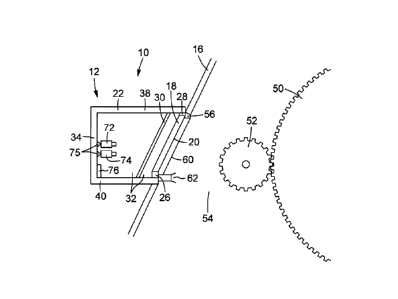
A prior art gear guard 16 is shown in Figure 1. It has an inspection window
14, which is directed
to the interior 54 of the gear guard where the gear set, which comprises a
girth gear 50 and a
pinion gear 52 are housed.
An installation, generally referred to as 10, is shown in Figure 2. The
installation 10 has an
enclosure, generally referred to as 12, that is sized to fit in an inspection
window 14 of a gear
guard 16. A pair of doors 18 are retractably attached to the enclosure 12 at a
front 20. In one
embodiment, the doors 18 are attached to the frame 22 of the enclosure 12 with
hinges. In
another embodiment, the doors 18 are in slidable engagement with a pair of
lower slides 26 and
a pair of upper slides 28 in the frame 22. In both embodiments, a light
transparent protective
barrier 30 is located behind the doors 18 in the interior 32 of the enclosure
12. As shown in
Figure 2 and 3, the enclosure 12 has a back 34, sides 36, a top 38, a bottom
40 and the front 20
which are constructed of metal, with the exception of the light transparent
protective barrier 30.
As shown in Figure 4, the light transparent protective barrier 30 covers the
opening 42 defined
by the open doors 18 and the front 20. The light transparent barrier 30 is
releasably retained
with clamps 43 and there is a gasket 45 between the light transparent barrier
30 and the frame
47 that retains it. The front 20 faces the gear set which includes a girth
gear 50 and a pinion gear
52, which are located in the interior 54 of the gear guard 16. An air blade
blower 56 is mounted
on the front 20 of the enclosure 12, proximate or at the top 38. The air blade
blower 56 has a
linear aperture 58 that is at least as wide as the light transparent
protective barrier 30. Air is
forced through the linear aperture 58 at high velocity to produce an air blade
60 that covers the
opening 42. As shown in Figure 5, at least one nozzle 62 and preferably two or
more nozzles 62
are attached to the enclosure 12 and are directed to the gear set 50, 52. The
nozzles 62 include
a quick release mechanism 64 which is for attachment to hosing 67. The quick
release
mechanism 64 is preferably a push to connect coupler or a lug push to connect
coupler. The
hosing 67 is in fluid communication with a cleaning solution.
CA 3026919 2018-12-05
As shown in Figure 6, a system, generally referred to as 70 is housed in the
enclosure 12 of the
installation 10. The system 70 includes: a thermal imaging device 72, which
may be, but is not
limited to an infrared camera, an infrared non-contact temperature sensor, a
thermal imager, or
a thermal smartphone module; a visible light camera 74; a computer 76; a
programmable logic
controller 78; and a user interface 80, which may be integral to the computer
76 and may be a
touch screen and is located on the outside of the back 34 of enclosure 12.
Returning to Figure 2,
both the visible camera 74 and the thermal imaging device 72 are mounted on
pivot mounts 75.
As shown in Figure 6, the computer 76 is in electronic communication with the
infrared camera
72, the visible light camera 74 and the programmable logic controller 78. The
programmable
logic controller 78 is in electrical communication with the air blade-type
blower 56, a pair of door
actuators 82, the infrared camera 72, the visible light camera 74, a power
supply 84, an alarm 86,
the solenoid valve 88 that controls the air blade-type blower 56, and a strobe
light 90. In an
alternative embodiment, the computer 76 is remote to the remainder of the
system 70 but is in
electronic communication with the system 70. The visible light camera 74
operates at a high
shutter speed, for example about 1/200th of a second to about 1/1000th second
or faster. The
visible light camera 74 may be a video camera.
In an alternative embodiment, shown in Figure 7A, the air blade blower 56 is
replaced with a
series of high pressure nozzles 92, which may be a manifold 94 with a series
of nozzles 92. In
another alternative embodiment shown in Figure 7B, the user interface 80 may
be replaced with
a panel 95 with buttons 96 that are in electrical communication with the
computer 76 and the
programmable logic controller 78. This allows for a manual override of the
system 70. As would
be known to one skilled in the art, the various alternative embodiments may be
combined with
one another in any configuration.
As shown in Figure 8, the gear set continues to turn at standard operating
speed. The
programmable logic controller 78 is turned on 190 and starts 200 the air blade
type blower 56
and activates 202 the door actuators, producing 204 an air blade 60 (a laminar
flow of high
velocity air) and the doors opening 206, respectively. The programmable logic
controller 78 then
starts 208 the visible light camera 74, which takes 210 stop action photos,
while at the same time,
starts 212 both the thermal imaging device 72, which collects 214 thermal
images and the strobe
11
CA 3026919 2018-12-05
light 90. The photographs and images may be collected for about 30 seconds and
are sent 216
to the computer where the data are stored 218 and analyzed 220. Then the
programmable logic
controller 78 instructs 222 the visible light camera 74 and the thermal
imaging device 72 to stop
taking photos and collecting images, respectively. The devices 72, 74 stop
224. The
programmable logic controller 78 instructs 226 the actuators 82 to close the
doors and the doors
close 228. The programmable logic controller 78 then instructs 230 the air
blade type blower 56
to stop and it stops 232.
A block diagram of data analysis is shown in Figure 9. The raw data are sent
300 from the thermal
imaging device 72 to the computer 76, where they are stored 302 as raw data.
Raw data may be
displayed 303 as a thermograph on the user interface 78. The raw data are
analyzed 304 and the
analyzed data are archived 306 and displayed 308 as three-dimensional images
on a user
interface 84, which may be integral with the computer 76 or may be separate.
The pinion Delta
Temperature (AT) is determined 310 by the computer and is the temperature
variation from the
far left of the pinion gear tooth to the far right of the pinion gear tooth.
This is typically the
number used to determine the quality of the pinion to gear alignment. A
properly aligned pinion
gear will have a higher temperature on the right/drive end of the tooth than
on the left end of
the tooth. The temperature can be displayed on a graph of temperature versus
distance from
one end of the gear tooth to the other end of the gear tooth.
For wear, the data are associated 312 with time stamps to produce 314
predictive models for
wear.
Example 1:
For bearings and bearing races, the combination of the two cameras, the
infrared camera and
the machine vision camera, provide detailed information on the state of the
bearings in the
bearing race. Wear and breakage can be identified by comparing the edge
characteristics of a
new bearing to that of a bearing that is in the bearing race and is
functioning under normal
operating conditions. A region of higher heat will be indicative of wear or
breakage. The
photographs from the visible light camera (machine vision) will show breakage
and may show
wear. The visible light camera photographs may be analyzed using edge
detection software or
12
CA 3026919 2018-12-05
can be reviewed by an operator. Contamination may also be seen in the
photographic images
from the visible light camera and from an increase in temperature in the
infrared images. Poor
lubrication patterns can also be seen in the photographic images from the
visible light camera
and from an increase in temperature in the infrared images. The data can be
archived as raw data
and can be analyzed and archived as analyzed data.
Example 2:
For girth gear sets, the combination of the two cameras, the infrared camera
and the machine
vision camera, provide detailed information on the state of the pinion gear.
Wear and breakage
can be identified by comparing the edge characteristics of a new gear tooth to
that of a gear
tooth that is functioning under normal operating conditions. A region of
higher heat will be
indicative of wear or breakage. The photographs from the visible light camera
(machine vision)
will show breakage and may show wear. The visible light camera photographs may
be analyzed
using edge detection software or can be reviewed by an operator. The machine
vision camera
takes photographs of a new gear tooth, then edge detection software traces the
edge of a new
tooth and records the data that represent the edge of the new gear tooth.
These data are then
used to compare the edge of a gear tooth of interest to the edge of the new
gear tooth by again
photographing the gear tooth of interest, applying the edge detection software
to the
photographs to obtain a data set representative of the edge of the tooth of
interest and
comparing the data. Contamination may also be seen in the photographic images
from the visible
light camera and from an increase in temperature in the infrared images. Poor
lubrication
patterns can also be seen in the photographic images from the visible light
camera and from an
increase in temperature in the infrared images. The data can be archived as
raw data and can be
analyzed and archived as analyzed data. Predictive models of wear can be
developed from the
data collected over time.
13
CA 3026919 2018-12-05