Note: Descriptions are shown in the official language in which they were submitted.
MARKING A COMPUTERIZED MODEL OF A CARDIAC SURFACE
FIELD OF THE INVENTION
The present invention relates to the display of
electroanatomical information.
BACKGROUND
In some electroanatomical mapping procedures, a catheter,
comprising one or more electrodes, is inserted into the heart,
and the electrodes are then used to acquire intracardiac
electrocardiographic (ECG) signals from the surface of the
heart.
SUMMARY OF THE INVENTION
There is provided, in accordance with some embodiments of
the present invention, a system that includes an electrical
interface and a processor.
The processor is configured to
receive, via the electrical interface, an electrocardiographic
signal from an electrode within a heart of a subject, to
ascertain a location of the electrode in a coordinate system of
a computerized model of a surface of the heart, to select
portions of the model responsively to the ascertained location,
such that the selected portions are interspersed with other,
unselected portions of the model, and to display the model such
that the selected portions, but not the unselected portions,
are marked to indicate a property of the signal.
In some embodiments, the processor is configured to select
the portions of the model by:
projecting a plurality of rays from the ascertained
location, and
selecting the portions of the model in response to points
1
CA 3027395 2018-12-13
at which the rays intersect the model.
In some embodiments, the processor is configured to, in
selecting the portions of the model, set a density of the
selected portions as a decreasing function of a distance from
the model of the ascertained location.
In some embodiments, the processor is configured to, in
selecting the portions of the model, set a spread of the
selected portions as an increasing function of a distance, from
the model, of the ascertained location.
In some embodiments,
the signal is a first signal and the electrode is a first
electrode,
the processor is further configured to receive a second
electrocardiographic signal from a second electrode within the
heart, and
the processor is configured to display the model such that
at least some of the other portions of the model are marked to
indicate the property of the second signal.
In some embodiments, the property is a first property, and
the processor is configured to display the model such that at
least some of the other portions of the model are marked to
indicate a second property of the signal.
In some embodiments, the processor is configured to
display the model such that the selected portions of the model
are colored to indicate the property.
In some embodiments, the property of the signal is a
dominant frequency of the signal.
In some embodiments, the processor is configured to, in
selecting the portions of the model, set a density of the
selected portions responsively to a feature of a frequency
2
CA 3027395 2018-12-13
spectrum of the signal at the dominant frequency.
In some embodiments, the processor is configured to, in
selecting the portions of the model, set a spread of the
selected portions responsively to a feature of a frequency
spectrum of the signal at the dominant frequency.
In some embodiments, the property of the signal is a cycle
length of the signal.
In some embodiments, the processor is configured to select
the portion of the model such that a density of the selected
portions decreases with distance from a point on the model that
is closest to the ascertained location.
There is further provided, in accordance with some
embodiments of the present invention, a method that includes
receiving, by a processor, an electrocardiographic signal from
an electrode within a heart of a subject, ascertaining a
location of the electrode in a coordinate system of a
computerized model of a surface of the heart, selecting
portions of the model responsively to the ascertained location,
such that the selected portions are interspersed with other,
unselected portions of the model, and displaying the model such
that the selected portions, but not the unselected portions,
are marked to indicate a property of the signal.
The present invention will be more fully understood from
the following detailed description of embodiments thereof,
taken together with the drawings, in which:
BRIEF DESCRIPTION OF THE DRAWINGS
Fig. 1 is a schematic illustration of a system for
3
CA 3027395 2018-12-13
displaying a computerized model of a surface of a heart of a
subject, in accordance with some embodiments of the present
invention;
Fig. 2 is a schematic illustration of a portion of a
computerized model of a surface of a heart, in accordance with
some embodiments of the present invention; and
Figs. 3-4 are schematic illustrations of techniques for
displaying a computerized model of a surface of a heart, in
accordance with some embodiments of the present invention.
DETAILED DESCRIPTION OF EMBODIMENTS
OVERVIEW
Embodiments described herein include techniques for
displaying electroanatomical information, whereby a
computerized anatomical model of a surface of a heart is
"sprayed" with colors, and/or other markings, indicating
electrical properties of the surface.
Per these techniques,
for each electrode that acquires an ECG signal from the
surface, a processor ascertains the location of the electrode
in the coordinate system of a model of the surface.
The
processor then marks some portions of the model in the vicinity
of this location, to indicate a property, such as a dominant
frequency, of the ECG signal. The density and/or spread of the
marked portions may be a function of the distance of the
electrode's location from the model, of various features of the
signal, and/or of the portions' locations. For example:
(i) The density of the marked portions may be a decreasing
function of the distance of the electrode's location from the
model. Alternatively or additionally, the spread of the marked
portions - i.e., the amount of surface area on the model that
4
CA 3027395 2018-12-13
is covered at least partly by the marked portions - may be an
increasing function of this distance. By changing the density
and/or spread of the marked portions as a function of the
distance of the electrode from the model, the processor
provides the physician with an intuitive visual indication of
this distance, which in turn reflects the quality of the
acquired ECG signal.
(The quality increases as the distance
decreases.)
(ii) When marking the model to show a dominant frequency
of an ECG signal, the density and/or spread of the marked
portions may be an increasing function of the amplitude and/or
width of the frequency spectrum of the signal at the dominant
frequency.
The physician is thus provided with an intuitive
indication of the amplitude and/or width at the dominant
frequency.
5
CA 3027395 2018-12-13
(iii) The density of the marked portions may decrease with
distance from the point on the model that is closest to the
electrode's location.
The techniques described herein are particularly helpful
for displaying regions of tissue that lie between two
electrodes.
For example, if two electrodes record,
respectively, two different dominant frequencies, the model may
be colored in a first color at the point that is closest to the
first electrode, in a second color at the point that is closest
to the second electrode, and in both colors - interspersed with
one another - between the two electrodes.
(The relative
dominance of one color over the other in this intermediate
region may be a function of any of the factors described above,
such as distance from each of the closest points, and/or the
respective amplitudes of the two frequency spectra at their
respective dominant frequencies.)
This provides a more
accurate representation of the cardiac surface, relative to
other, hypothetical techniques that are not within the scope of
the present disclosure.
For example, one hypothetical technique might interpolate
the two colors, such that the region between the electrodes is
shown in varying degrees of interpolation. For example, if one
electrode records 12 Hz and another electrode records 18 Hz, 12
Hz may be mapped to red, 18 Hz may be mapped to blue, and the
region between the two electrodes may be shown in varying
shades of purple.
Such interpolation, however, may be
misleading, as it implies that the cardiac surface exhibits
dominant ECG frequencies between 12 Hz and 18 Hz. In contrast,
embodiments of the present invention may color the intermediate
region in both red and blue, but not in purple, indicating that
this region exhibits dominant ECG frequencies of both 12 Hz and
6
CA 3027395 2018-12-13
18 Hz, but not frequencies between 12 Hz and 18 Hz.
Although the present description relates mainly to
electroanatomical mapping applications, it is noted that the
techniques described herein may be used for any suitable
application that requires extrapolating, over a surface,
measurements that were acquired at discrete points on the
surface.
SYSTEM DESCRIPTION
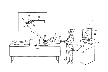
Reference is initially made to Fig. 1, which is a
schematic illustration of a system 20 for displaying a
computerized model 22 of a surface 30 of a heart 24 of a
subject 25, in accordance with some embodiments of the present
invention.
Fig. 1 depicts the performance of an electroanatomical
mapping procedure, whereby a physician 27 navigates a catheter
29 within heart 24, and, for various positions of the catheter,
a plurality of electrodes 32 at the distal end of catheter 29
record intracardiac ECG signals from surface 30 of the heart.
Typically, catheter 29 is equipped with one or more position
sensors (not shown), such that each recorded ECG signal may be
associated with the location of the electrode 32 that performed
the recording.
For example, catheter 29 may comprise one or
more electromagnetic position sensors, which, in the presence
of an external magnetic field, generate signals that vary with
the respective positions of the sensors.
Alternatively, to
track the position of each electrode 32, the processor may
ascertain the respective impedances between the electrode and a
plurality of electrodes coupled externally to subject 25 at
various different locations, and then compute the ratios
between these impedances. As yet another alternative, the
7
CA 3027395 2018-12-13
processor may use both electromagnetic tracking and impedance-
based tracking, as described, for example, in US Patent
8,456,182, whose disclosure is incorporated herein by
reference.
In some embodiments, as shown in Fig. 1, catheter 29 is a
basket catheter comprising, at its distal end, a basket 31 of
electrodes 32.
Alternatively, catheter 29 may have any other
suitable form, with electrodes 32 being arranged in any
suitable configuration.
System 20 comprises a processor (PROC) 28 and a display
26. As the ECG signals are acquired, the signals are passed,
via catheter 29 and an electrical interface 35 (such as a port
or socket), to processor 28.
Processor 28 uses the signals,
along with the associated electrode-location information, to
mark model 22 to indicate electrical properties of surface 30,
as described in detail below.
During and/or following the
mapping procedure, processor 28 may display model 22 on display
26.
In general, processor 28 may be embodied as a single
processor, or as a cooperatively networked or clustered set of
processors.
Processor 28 is typically a programmed digital
computing device comprising a central processing unit (CPU),
random access memory (RAM), non-volatile secondary storage,
such as a hard drive or CD ROM drive, network interfaces,
and/or peripheral devices.
Program code, including software
programs, and/or data are loaded into the RAM for execution and
processing by the CPU and results are generated for display,
output, transmittal, or storage, as is known in the art.
The
program code and/or data may be downloaded to the computer in
electronic form, over a network, for example, or it may,
alternatively or additionally, be provided and/or stored on
8
CA 3027395 2018-12-13
non-transitory tangible media, such as magnetic, optical, or
electronic memory.
Such program code and/or data, when
provided to the processor, produce a machine or special-purpose
computer, configured to perform the tasks described herein.
Reference is now made to Fig. 2, which is a schematic
illustration of a portion of model 22 of surface 30, as
displayed by processor 28, in accordance with some embodiments
of the present invention.
Typically, model 22 models the
anatomical features of surface 30 by a tessellation of tiles
40, having any suitable shape (such as a triangular shape),
which abut each other along edges 41 and vertices 38.
(In
practice, edges 41 and vertices 38 are not displayed on-
screen.)
As described above with reference to Fig. 1, processor 28
receives ECG signals from electrodes 32 during the
electroanatomical mapping procedure.
Further to receiving
these signals, processor 28 computes the respective spectra of
these signals, and/or process the signals in any other suitable
manner, to ascertain a property of the signals (and hence, of
the tissue from which the signals were acquired). For example,
the processor may ascertain the respective dominant frequencies
of the signals, and/or the respective cycle lengths of the
signals. The processor then designates a different respective
color, or other marking, to represent the property of each of
the signals.
Subsequently, as described in detail below with
reference to Figs. 3-4, for each of the signals, the processor
selects portions of the model responsively to the location of
the electrode that acquired the signal, and then displays model
22 such that the selected portions (but not any unselected
portions) of the model are marked, using the designated
marking, to indicate the property.
9
CA 3027395 2018-12-13
For example, Fig. 2 shows a first frequency spectrum 34a,
derived from a first ECG signal received from a first
electrode, and a second frequency spectrum 34b, derived from a
second ECG signal received from a second electrode.
From
spectrum 34a, processor 28 ascertains that the first signal has
a dominant frequency of Fl, and from spectrum 34b, the
processor ascertains that the second signal has a dominant
frequency of F2.
(In the context of the present application,
including the claims, a "dominant frequency" may be any
frequency at which the relevant frequency spectrum attains a
local maximum value.)
Accordingly, the processor selects a
first indicator 36a to represent frequency Fl, and a second
indicator 36b to represent frequency F2.
Subsequently, the
processor marks selected portions of model 22, by overlaying
first indicator 36a or second indicator 36b on the each of the
selected portions.
Each of the indicators used for marking the model may
include any suitable symbol(s), such as the symbols shown in
Fig. 2, and/or any suitable character(s).
For example,
alternatively to using the symbols shown in Fig. 2, the
processor may overlay each selected portion of the model with
the value of Fl or F2, e.g., by overlaying "12" to indicate a
dominant frequency of 12 Hz. As
another alternative, the
processor may designate a first color to represent frequency Fl
and a second color to represent frequency F2, and then display
the model such that each of the selected portions of the model
is colored, in either the first color or the second color, to
indicate frequency Fl or frequency F2.
(The processor may
further display a key, which indicates the meaning of each of
the colors or indicators.)
In some embodiments, as shown in Fig. 2, each of the
CA 3027395 2018-12-13
selected portions of model 22 comprises a respective tile 40.
That is, the processor colors, and/or overlays an appropriate
indicator on, each selected tile 40.
Alternatively or
additionally, the processor may mark selected vertices 38, by
coloring, and/or overlaying an appropriate indicator on, each
selected vertex.
As noted above in the Overview, in general, using the
techniques described herein, the model is "sprayed" with color
and/or with other markings, such that portions of the model
marked with a first type of marking may be interspersed with
other portions of the model that are marked with a second type
of marking, or are not marked at all.
For example, Fig. 2
shows a region 33 of the model in which two kinds of markers
are interspersed with one other. As
noted above in the
Overview, interspersing the markers in this manner provides a
more accurate visual representation of the electrical
properties of the tissue, relative to other techniques that use
interpolation.
It is noted that the scope of the present disclosure
includes processing the signals from the electrodes, and
marking model 22 in response thereto, in real-time, i.e.,
during the procedure as the data are collected, and/or offline,
subsequently to the procedure.
Reference is now made to Fig. 3, which is a schematic
illustration of a technique for displaying model 22, in
accordance with some embodiments of the present invention.
The left portion of Fig. 3 shows an arm of catheter 29,
comprising a first electrode 32a and a second electrode 32b,
positioned near surface 30 of the heart.
First electrode 32a
is at a first distance D1 from the surface, while second
11
CA 3027395 2018-12-13
electrode 32b is at a second distance D2 from the surface, D2
being greater than Dl. At these positions, electrodes 32a and
32b acquire ECG signals from surface 30.
As described above with reference to Fig. 1, processor 28
ascertains the location of each of the electrodes in the
coordinate system of model 22. Accordingly, the middle portion
of Fig. 3 shows the location Li of first electrode 32a and the
location L2 of second electrode 32b in the coordinate system of
model 22, as ascertained by the processor.
After ascertaining the electrodes' locations, the
processor projects a plurality of rays 42 from each of the
ascertained locations, as further shown in the middle portion
of Fig. 3.
For example, considering the location of the
electrode as the center of a sphere, the processor may project
a different respective ray 42 for each pair of angles (6, p),
where 6 (the polar angle in spherical coordinates) runs between
0 and 180 degrees with a given step size (e.g., 5 or 10
degrees), and p (the azimuthal angle in spherical coordinates)
runs between 0 and 360 degrees with another given step size
(e.g., 5 or 10 degrees), such that rays 42 are projected in a
spherical formation.
For each set of projected rays, the processor selects
portions of the model in response to the points 44 at which the
rays intersect the model.
For example, the processor may
select each tile that is struck by at least one of the rays.
(If a given tile is struck by two rays projected from different
respective electrode locations, the processor may randomly
choose one of the rays as the "winner" of the collision.)
Alternatively, for each of intersection points 44, the
processor may select the vertex that is closest to the
intersection point.
12
CA 3027395 2018-12-13
Subsequently to selecting the relevant portions of model
22, the processor displays model 22 such that, for each of the
electrodes, portions of the model selected for the electrode
are marked to indicate a property, such as a dominant
frequency, of the signal that was received from the electrode.
For example, as shown at the right portion of Fig. 3, the
processor may render model 22 such that each of the selected
portions for electrode 32a are marked with indicator 36a to
indicate a property of the ECG signal from electrode 32a, and
each of the selected portions for electrode 32b are marked with
indicator 36b to indicate the property of the signal from
electrode 32b.
(For simplicity, the anatomical details of
model 22 are not shown in Fig. 3 or Fig. 4.)
A result of using the above-described ray-projection
technique is that, for each of the electrodes, the density of
the selected (and marked) portions is a decreasing function of
the distance from the model of the ascertained location of the
electrode.
(This "density" may be quantified, for example, as
the number of selected portions per unit of surface area of
model 22, or per unit of area on display 26.) A further result
of the ray-projection technique is that the spread of the
selected (and marked) portions is an increasing function of the
distance from the model of the ascertained location of the
electrode.
(This "spread" may be quantified, for example, as
the geodesic distance along the surface of the model, or the
distance along display 26, from the point on the model that is
closest to the electrode's location, to the selected portion
that is farthest from this closest point.)
For example, in Fig. 3, indicators 36a are at a greater
density than are indicators 36b, as a result of the smaller
distance of electrode 32a from surface 30, relative to
13
CA 3027395 2018-12-13
electrode 32b. Likewise, while indicators 36a are enclosed by
a circle having a smaller radius R1, indicators 36b are
enclosed only by a circle having a larger radius R2.
Notwithstanding the particular example technique described
above, it is noted that the scope of the present disclosure
includes any suitable technique for setting the density as a
decreasing function of the distance of the electrode's location
from the model, and/or setting the spread as an increasing
function of this distance.
Reference is now made to Fig. 4, which is a schematic
illustration of another technique for displaying model 22, in
accordance with other embodiments of the present invention.
Fig. 4 illustrates a scenario in which a single electrode
captures an ECG signal whose spectrum 34c exhibits two dominant
frequencies: a first dominant frequency F3, and a second
dominant frequency F4. In
response to identifying these two
dominant frequencies, the processor selects two indicators (or
colors), one indicator (or color) for each of the frequencies.
In the particular case shown, the processor selects indicator
36a for F3, and indicator 36b for F4. The
processor then
displays model 22 such that portions of the model marked to
indicate frequency F3 are interspersed with other portions of
the model marked to indicate frequency F4. This provides the
physician with an intuitive visual indication of the two
different dominant frequencies.
In general, the above-described technique may be applied
to any scenario in which two different properties of an ECG
signal - such as two different cycle lengths - are ascertained.
In other words, some portions of the model in the vicinity of
the electrode may be marked to indicate the first property,
14
CA 3027395 2018-12-13
while other portions of the model, which are interspersed with
the former portions, may be marked to indicate the second
property. This technique may be similarly applied in cases in
which more than two properties of the signal are ascertained.
Fig. 4 further illustrates that the density and spread of
the selected (and marked) portions of the model may be set
responsively to features of frequency spectrum 34c at the
respective dominant frequencies of the signal.
For example,
for each of the dominant frequencies, the density of the
selected portions may be an increasing function of the
amplitude of the frequency spectrum at the dominant frequency.
Fig. 4 illustrates such an embodiment, by showing the marking
density for frequency F3, which has a larger amplitude A3, as
being greater than the marking density for frequency F4, which
has a smaller amplitude A4. Alternatively or additionally, the
spread may be an increasing function "f" of the width of the
frequency spectrum at the dominant frequency.
Fig. 4
illustrates such an embodiment, by showing the spread for
frequency F4, quantified by a radius R4, being greater than the
spread for frequency F3, quantified by the radius R3, as a
result of the greater width W4 of the spectrum at F4, relative
to the width W3 at F3.
(The width may be quantified, for
example, as a full width at half maximum.)
Notwithstanding the specific embodiments described above,
it is noted that, when marking to indicate a dominant
frequency, each of the density and spread of the marking may be
any suitable increasing or decreasing function of the amplitude
at the dominant frequency, the width at the dominant frequency,
and/or any other suitable feature of the signal in the time- or
frequency-domain. Likewise, when marking to indicate any other
property of the signal (such as a cycle length), each of the
CA 3027395 2018-12-13
density and spread may be set by applying any suitable function
to any suitable feature(s) of the signal in the time- or
frequency-domain.
In some embodiments, to perform the techniques described
above with reference to Fig. 4, the processor first finds the
point on the model that is closest to the location of the
electrode. The processor then calculates the maximum geodesic
distance from the closest point at which a portion of the model
may potentially be marked.
(This distance corresponds to the
marking spread.) The processor then iterates over all relevant
portions (e.g., over all tiles or vertices) of the model within
the calculated distance of the closest point, and decides,
based on the desired marking density, whether to mark the
portion.
For example, the processor may generate a random
number, and then compare the random number to a threshold that
is a function of the desired marking density. In
response to
this comparison, the processor may decide whether to mark the
portion.
(Alternatively or additionally to the threshold being
a function of the desired marking density, the distribution
from which the random number is generated may be a function of
the desired marking density.)
For example, for each relevant portion of the model within
the calculated distance of the closest point, the processor may
generate a random number from a uniform distribution between 0
and 1. The processor may then ascertain whether this number is
less than a particular threshold. If
yes, the processor may
mark the portion; otherwise, the processor may refrain from
marking the portion.
The threshold may be closer to 1 for a
higher marking density, and closer to 0 for a lower marking
density.
Alternatively, more complex algorithms may be used
for determining the distribution of the marked portions of the
16
CA 3027395 2018-12-13
model.
Alternatively or additionally to setting the density
responsively to features of the signal, the density may
decrease with distance from the point on the model that is
closest to the location of the electrode.
It will be appreciated by persons skilled in the art that
the present invention is not limited to what has been
particularly shown and described hereinabove.
Rather, the
scope of embodiments of the present invention includes both
combinations and subcombinations of the various features
described hereinabove, as well as variations and modifications
thereof that are not in the prior art, which would occur to
persons skilled in the art upon reading the foregoing
description.
Documents incorporated by reference in the
present patent application are to be considered an integral
part of the application except that to the extent any terms are
defined in these incorporated documents in a manner that
conflicts with the definitions made explicitly or implicitly in
the present specification, only the definitions in the present
specification should be considered.
17
CA 3027395 2018-12-13