Note: Descriptions are shown in the official language in which they were submitted.
CA 03027522 2018-12-12
WO 2017/216749
PCT/IB2017/053556
"Glasses with extensions."
DESCRIPTION
The present invention concerns the technical field of eyeglasses. The present
invention is applicable to sight-correcting eyeglasses, sunglasses or any
other type of
eyeglasses. In particular, the present invention concerns eyeglasses to which
a pair of
extensions is applied.
Known eyeglasses comprise a frame front and two temples, attached to the
frame front, and configured to pass over the ears of a user and rest on them.
The frame
front comprises two lenses, or a single lens, through which the user can look
to
improve his/her vision. The frame front also comprises a nose pad configured
to rest
on the user's nose.
The temples, together with the nose pad, allow the eyeglasses to remain in
position on the user's face when he/she uses the eyeglasses looking through
the
lenses. In particular, each temple has a temple tip at the distal end with
respect to the
frame front.
In some situations the user needs to frequently put on and take off the
eyeglasses. This happens particularly in the use of reading eyeglasses, if the
user has
to alternately observe distant and close objects, and in the use of
sunglasses, if there
are sudden changes of light, for example while driving in and out of tunnels.
For the sake of ease of use, it is desirable that, when the user is not
looking
through the lenses, he doesn't need to remove the glasses but to simply to
wear them
in a different position.
A known solution is given by the use of a chain that joins the temples and
allows the eyeglasses to be worn around the neck. The temples of the
eyeglasses in
particular are inserted in specific eyelets in the chain.
However, the same chain can be excessively long or excessively short
depending on the physiognomy of the user. Chains that are too long may cause
wide
1
CA 03027522 2018-12-12
WO 2017/216749
PCT/IB2017/053556
oscillations of the eyeglasses at the user's neck when he/she moves, with the
risk of
the eyeglasses striking external objects.
Moreover, eyeglass chains may easily entangle and hold the eyeglasses,
causing discomfort to the user's neck.
An object of the present invention is to solve the aforementioned problems, in
particular by limiting the possibility of movement of the eyeglasses when worn
around the neck, and the consequent risk of impacts.
A further object of the invention is to allow eyeglasses to be worn at the
neck
avoiding the risk that the eyeglasses entangle with external objects.
These and other objects are accomplished by an eyeglass or a pair of
eyeglasses according to any one of the claims in the following.
Advantageously, in the use configuration the second segments of each
extension can rest behind the user's neck, supporting the eyeglasses.
Consequently,
the eyeglasses do not hang excessively down from the neck, and their mobility
is
reduced. Moreover, the eyeglasses can be supported on the neck without the
presence
of elements that can get entangled.
Further features and advantages of the eyeglasses according to the present
invention will become clear from the following description of a preferred
embodiment, given by way of a non-limiting illustration, with reference to the
attached figures, in which:
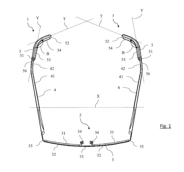
- figure 1 shows a perspective view of eyeglasses according to the present
invention;
- figure 2 shows a perspective view of one of the extensions applied to the
temples of the eyeglasses of figure 1,
- figure 3 shows a section view of the extension of figure 2,
- figures 4 and 5 show a section view of the extension of figure 2 coupled
with
respective temple tips of eyeglass temples having different dimensions.
2
CA 03027522 2018-12-12
WO 2017/216749
PCT/IB2017/053556
With reference to the attached figures, reference an extension for eyeglasses
is
globally designated with numeral 1. The extension 1, which is described more
hereinafter, is applicable to eyeglasses 2.
The eyeglasses 2 comprise a frame front 3 and a pair of temples 4. The frame
front 3 comprises at least one lens 31, like in the case of goggles, or plural
lenses 31,
preferably two. The frame front can also comprise one or more rims 32 to keep
the
lenses 31 in position, a bridge 33 joining the rims 32, two nose pads 34
configured to
rest on a user's nose, and two end pieces 35 configured to connect to the
temples 4.
Such features are known to those skilled in the art and therefore are not
described any
.. further hereinafter.
The temples 4 mirror one another. Each temple 4 is attached to the frame front
3, for example at one of the end pieces 35. Preferably, each temple 4 is
hinged to the
frame front 3. Preferably, moreover, the temples 4 are adapted to switch
between a
closed position, in which the temples 4 lie close to the frame front 3, and an
open
position, in which the temples 4 are substantially parallel and spaced apart
from one
another in a longitudinal direction X.
In the following of the description, unless specified otherwise, the
directions
and the distances refer to the eyeglasses with the temples 4 in the open
position.
In particular, each temple 4 comprises a stem 41 and a temple tip 42. The stem
41 is substantially rectilinear. The stem 41 is arranged between the frame
front 3 and
the respective temple tip 42. The temple tip 42 is thus in distal position
with respect to
the frame front 3. In the open position the temples 4, and in particular the
stems 41,
define a plane of the temples 4.
The temple tip 42 may be formed with different shapes and sizes. The temple
tip 42 is generally defined by an end portion of the temple 4. If the stem 41
is made of
metal, the temple tip 42 may comprise a plastic coating (not illustrated), to
promote a
pleasant contact with the head of a user.
3
CA 03027522 2018-12-12
WO 2017/216749
PCT/IB2017/053556
The temple tip 42 may be inclined with respect to the stem 41 of the
respective
temple 4, and in the open position the temple tip 42 extends outside of the
plane
defined by the stems 41 of the temples 4. Preferably, each temple tip 42 forms
an
obtuse angle with the stem 41 of the respective temple 4 so as to fit around
the ear of a
user.
Each temple tip 42 has an end portion 43. The end portion 43, or possibly the
entire temple tip 42, extends mainly along a main direction of extension Y. It
should
be noted that the temple tips 42 of the temples 4 extend in two distinct
respective
main directions of extension Y.
According to the illustrated embodiment, the temple tip 42 has a substantially
flat end portion 43. In other words, the end portion 43 has a cross section
that defines
a first W and a second section direction Z, perpendicular to each other and
perpendicular to the main direction of extension Y. In particular, the cross
section of
the end portion 43 extends in the second section direction Z for a shorter, or
negligible, length with respect to an analogous length in the first section
direction W.
Generally, the second section direction Z extends towards the user's head, so
that the
end portion 43 offers a smooth surface to the user.
According to three different preferred standard types, temple tips 42 have a
size in section equal, respectively, to 3 mm, 5 mm, and 13 mm. In particular,
it should
be observed that there are eyeglasses having temple tips 42 of a thin type and
eyeglasses having temple tips 42 of a wide type.
In this description the section dimensions of a given element must always,
unless indicated otherwise, be taken to mean the maximum dimensions of such an
element that can be measured perpendicular to the main direction of extension
Y of
the temple tips 42, for example in the first section direction W or in the
second section
direction Z.
According to an aspect of the invention, two extensions 1 are applicable
4
CA 03027522 2018-12-12
WO 2017/216749
PCT/IB2017/053556
jointly to eyeglasses 2, as shown in figure 1. As will become clearer in the
following
of the description, each extension 1 is adaptable to at least two eyeglasses
having
distinct types of temple tips 42, i.e. a thin type and a wide type, in which
the temple
tips 42 according to the wide type have section dimensions greater with
respect to
temple tips 42 of the thin type.
For example, temple tips 42 can be considered to fall in the thin type if
their
section dimensions are less than 3.5 mm, and in the wide type if their section
dimensions are greater than 4.5 mm.
The two extensions 1 have the same features, and mirror one another. In other
words, the shape of either one of the extensions 1 can be obtained from the
shape of
the other extension 1 by symmetry with respect to a plane.
The two extensions 1 are mutually distinct and separate elements. The features
indicated for a single extension 1 or for single mirroring parts of the
eyeglasses 2
should be considered to be applicable to both extensions 1 or to both the
corresponding mirroring parts of the eyeglasses 2.
Each extension 1 has a body 5. According to an embodiment, the body 5 is
made of elastomeric material. More preferably, the body 5 is made of silicone
rubber,
manufactured for example by liquid silicone rubber moulding. Such a material
has
different advantageous features, including flexibility, resistance to low and
high
temperatures, to ultraviolet rays and to ageing. Advantageously, such a
material may
have an elongation at break comprised between 400% and 700%, a Shore A
hardness
comprised between 30 and 70, and a tensile strength comprised between 5 N/mm2
and
12 N/mm2, preferably between 9 N/mm2 and 11 N/mm2.
The body 5 extends between a first end 51 and a second end 52. The body 5
has a first segment 53 and a second segment 54. In particular, the first end
51 is
located on the first segment 53, and the second end 52 is located on the
second
segment 54.
5
CA 03027522 2018-12-12
WO 2017/216749
PCT/IB2017/053556
Each extension 1 is configured to be fixed to a respective temple tip 42 of
the
eyeglasses 2. In particular, the first segment 53 is adapted to be fixed to
the temple tip
42.
In the following of the description, unless specified otherwise, the mutual
positions of the eyeglasses 2 and of the extensions 1 are intended to be
concomitant
with the two extensions 1 being fixed to the respective temple tips 42 (always
with the
temples 4 in open position). In particular, the references to the main
directions of
extension Y, to the first W and to the second Z section direction refer to the
position
in which the two extensions 1 are fixed to the respective temple tips 42.
The first segment 53 extends mainly in the cited main direction of extension
Y. Preferably, the first segment 53 has a cavity 55 configured to reversibly
receive the
temple tip 42. In particular, the cavity 55 receives the temple tip 42 along
the main
direction of extension.
The body 5 has an opening 56 at the first end 51 adapted to be passed through
by the temple tip 42 to allow the insertion of the temple tip 42 in the cavity
55. The
cavity 55 has a bottom 57 opposite the opening 56.
Preferably, the opening 56 has a substantially elliptical shape to retain the
temple tip 42, in particular its end portion 43, and to prevent the rotation
of the
extension 1 with respect to the temple tip 42. In particular, the opening 56
has
dimensions in the first section direction W greater with respect to its
dimensions in
the second section direction Z, in a similar manner as already described
relative to the
end portion 43 of the temple tip 42.
Advantageously, when the temple tip 42 is inserted in the cavity 55 through
the opening 56, the orientation of the extension 1 is fixed.
Preferably, the opening 56 and/or the cavity 55 are elastically deformable to
allow the insertion and the retention of the temple tip 42 in the cavity 55.
Advantageously, it is necessary for the user to apply a force to withdraw the
temple
6
CA 03027522 2018-12-12
WO 2017/216749
PCT/IB2017/053556
tip 42 from the cavity, and the risk of its accidental extraction during use
is prevented.
According to the illustrated embodiment, the cavity 55 has a first portion 58
and a second portion 59. The first portion 58 of the cavity 55 is arranged
between the
opening 56 and the second portion 59 of the cavity 55. For example, in the
preferred
embodiment the second portion 59 of the cavity 55 is located at the bottom 57
of the
cavity 55.
The opening 56 has section dimensions smaller with respect to the section
dimensions of the first portion 58. The second portion 59 also has section
dimensions
smaller with respect to the section dimensions of the first portion 58, for
example
dimensions substantially equal to the section dimensions of the opening 56.
In detail, the first portion 58 of the cavity 55 defines a seat adapted to
receive
temple tips 42 of the wide type. The first portion 58 may be deformable to
receive
temple tips of the wide type. Moreover, the second portion 59 of the cavity 55
defines
a seat adapted to receive temple tips 42 of the thin type. The extensions 1
are therefore
suitable for being used both with eyeglasses 2 having temple tips 42 of the
thin type,
and with eyeglasses 2 having temple tips 42 of the wide type.
The opening 56 and the second portion 59 of the cavity 55 therefore define
each a narrowing of the cavity 55 with respect to the first portion 58. The
cavity 55 in
particular is configured to prevent the access of temple tips 42 of the wide
type to the
second portion 59 of the cavity 55.
Temple tips 42 of the thin and wide type can be distinguished from one
another since the temple tips 42 of the thin type are adapted to access to the
second
portion 59 of the cavity 55 whereas temple tips 42 of the wide type are
adapted to
access to the first portion 58 of the cavity 55 but not to the second portion
59. In
particular, the temple tips 42 of the wide type have section dimensions
greater than
the section dimensions of the second portion 59 and/or of the opening 56.
In the preferred embodiment for example the opening 56 and the second
7
CA 03027522 2018-12-12
WO 2017/216749
PCT/IB2017/053556
portion 59 have section dimensions equal to 3 mm, and the first portion 58 of
the
cavity 55 has section dimensions equal to 5 mm.
Advantageously, as shown in figure 4, wide temple tips 42 can pass through
the opening 56, which is deformable, and be housed in the first portion 58 of
the
cavity 56. This is sufficient to ensure the stability of positioning of the
temple tips of
the wide type in the cavity 55.
For example, temple tips 42 according to the standard type with section
dimensions of 5 mm are adapted to be housed in the first portion 58 without
deforming the first portion 58 of the cavity 55. On the other hand, as shown
in figure
4, temple tips 42 with section dimensions of 13 mm are adapted to be housed in
the
first portion 58 with deformation of the first portion 58 of the cavity 55.
Moreover, as shown in figure 5, temple tips 42 of the thin type, for example
according to the standard type having section dimensions equal to 3 mm, are
adapted
to be housed in the second portion 59 of the cavity 55. The temple tips 42 of
the thin
type therefore also pass through the opening 56 and the first portion 58 of
the cavity.
Advantageously, the temple tips 42 of the thin type can be held stably in two
distinct points, i.e. at the opening 56 and at the second portion 59 of the
cavity 55.
It should be observed that extensions 1 equipped with a cavity 55 having
substantially constant section are adapted to receive only temple tips 42
having
section dimensions in a limited range of values.
Moreover, extensions 1 in which the cavity 55 defines a single narrowing can
receive temple tips 42 both of the wide and thin type, but the thin temple
tips 42 have
excessive freedom of movement in the cavity 55. It is the case for example in
which
the opening 56 defines a narrowing with respect to the first portion 58 of the
cavity
55, but in which there is no second portion 59 as described above. Thin temple
tips 42
inserted in such a cavity 55 would indeed have the possibility of rotating
inside the
first portion 58, being held in position exclusively at the opening 56.
8
CA 03027522 2018-12-12
WO 2017/216749
PCT/IB2017/053556
A cavity 55 shaped according to the invention, on the other hand, is adapted
to
receive both thin temple tips 42 and wide temple tips 42, ensuring stable
positioning
also of thin temple tips 42.
Preferably, the extension 1 has a hole 11 to allow air to exit from the cavity
55
during the insertion of the temple tip 42 in the cavity 55. Advantageously,
the cavity
55 offers low mechanical resistance to the insertion of the temple tip 42.
The second segment 54 is inclined with respect to the first segment 53. The
second segment 54 extends along a main direction of extension T. In
particular, the
second segments 54 extend along two respective main directions of extension T,
distinct from one another. In detail, each second segment 54 has an extension
comprised between 2 cm and 8 cm, preferably equal to 3 cm.
When the first segments 53 are connected each to the respective temple tip 42,
the second segments 54 project from the respective temple tips 42. Moreover,
in such
a condition, the main directions of extension T of the second segments 54
converge
with each other, as shown for example in figure 1, so that the second segments
54 can
rest on a user's neck.
In particular, the distance between the temple tips 42 is greater than the
distance between the second segments 54 of the respective extensions 1. Such
distances are intended to be measured in the longitudinal direction X, and in
particular
in the plane of the temples 4, with the temples 4 in open position, and the
temple tips
42 connected to the first segments 53 of the respective extensions 1.
Again in such a configuration, each second segment 54 is inclined with respect
to the respective first segment 53 by an angle B between 1100 to 160 ,
measured on
the plane defined by the two temples 4, i.e. by the stems of the temples 41.
Such an
angle B in particular is identified by the projections of the first segments
53 and of the
respective second segments 54 on such a plane. In other words, the angle B is
defined
by the projections on the plane of the temples 4 of the main directions of
extension T
9
CA 03027522 2018-12-12
WO 2017/216749
PCT/IB2017/053556
of the second segments 54 and of the main directions of extension Y of the
respective
temple tips 42.
Advantageously, whereas in the absence of extensions 1 the neck of a user can
easily pass through the space comprised between the temple tips 42 of the
eyeglasses
2, in the presence of extensions 1 there is no longer sufficient space for the
passage of
the neck between the extensions 1, and the eyeglasses do not fall from the
neck.
It should be noted that, in order to ensure the orientation described above of
the second segments 54 with respect to the temple tips 42, i.e. with respect
to the first
segments 53, the main direction of extension T of each second segment 54 lies
in a
plane substantially perpendicular to the first section direction W of the
respective
temple tip 42, i.e. of the respective first segment 53.
Advantageously, as described above, the rotation of the extension 1 with
respect to the temple tip 42 is prevented. Consequently, the orientation of
the second
segment 54 is fixed. In particular, when the user wears the eyeglasses around
the
neck, such orientation at least partially faces behind the user's neck even
if, in non-
illustrated embodiments of the invention, the second segment 54 can also
develop in
part downwards, i.e. behind the user's shoulders.
The eyeglasses 2 according to the invention can be used by firstly fixing each
extension 1 to the respective temple tip 42. In particular, the fixing takes
place by
inserting the end portion 43 of the temple tip 42 in the cavity 55 through the
opening
56. In the insertion, the extension 1 is oriented with respect to the temple
tip 42 thanks
to the substantially flat shape of the end portion 43 of the temple tip 42 and
to the
elliptical shape of the opening 56.
Thereafter, a user can wear the eyeglasses 2 with the extensions 1 on the
face,
with the temple tips 42 resting on the ears, or he/she can wear the eyeglasses
2 around
the neck, with the second segments 54 of the extensions 1 resting behind the
neck.