Note: Descriptions are shown in the official language in which they were submitted.
TITLE OF THE INVENTION
FIBER CLEAVER
FIELD OF THE INVENTION
[0001] The present invention relates to the general field or fiber optics, and
more
specifically to a fiber cleaver.
BACKGROUND
[0002] Optical fibers are glass wires that are very transparent and are made
to
guide light. A fiber is composed of a core and a cladding. Because the core
has an
index of refraction that is higher than that of the cladding, the light is
guided in the
core. The vast majority of optical fibers are made with a pure silica glass
with a
slightly germanium doped core. Optical fibers are made to connect light from
light
sources to detectors or output devices. They need to be connected to devices
or
to each other. Since the light exits the end of the fiber, in order to make a
good
connection, the end of the fiber must be properly prepared. It can be cut and
polished or it can be cleaved. A cleave is achieved by applying a stress on
the
optical fiber, by pulling, bending or twisting, and introducing a defect on
the
surface of the optical fiber, for example by scribing with a blade that is
harder than
the glass. Because of the glass rigidity and the applied stress, the defect
will
propagate across the fiber, cleaving it. When properly done, this method
produces
a fiber's endface that is perfectly flat.
[0003] Good quality fiber cleavers, used to reliably make good quality cleaves
in
optical fibers, are relatively expensive and fragile. They typically require
fiber
Date Recue/Date Received 2023-04-11
2
clamps on both side of the cleaving point and a scribing tool that will
produce the
defect at the scribing point. Any non-glass protective coating on the fiber,
such as
the standard acrylate coating, must be removed before scribing to expose the
bare
fiber. Fiber cleaver design usually requires removing a relatively long
portion of the
optical fiber coating before cleaving. In turn, this will require a relatively
bulky
packaging to protect the exposed part of the fiber once subsequent operations,
such as splicing or attachment of a connector, have been performed.
Furthermore,
good quality fiber cleavers require a stable surface to support them in use,
and
require fiber manipulation with both hands, which may be inconvenient. They
are
usually made of many different mechanical parts that are assembled precisely
aligned to perform correctly, they are sensible to shock or temperature change
and
must be regularly realigned and calibrated, especially when they are moved
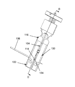
around, such for fiber optics installation in the field.
[0004] Against this background, there exists a need in the industry to provide
an
improved fiber cleaver.
SUMMARY OF THE INVENTION
[0005] In a broad aspect, the invention provides a fiber cleaver for cleaving
an
optical fiber, comprising: a monobloc fiber handling element made of a single
unitary and continuous piece of material, the fiber handling element defining
a pair
of spaced apart fiber holding portions, each fiber holding portion defining a
substantially elongated fiber receiving aperture for receiving a respective
part of
the optical fiber thereinto, the fiber receiving apertures being distanced
from each
other by an inter-aperture distance in a gap extending therebetween, the fiber
handling element being deformable between open, closed and tensing
Date Recue/Date Received 2023-04-11
3
configurations. In the open configuration, the fiber receiving apertures
extend
substantially coaxially relative to each other, the fiber receiving apertures
have an
open width and the inter-aperture distance has a first distance value. In the
closed
configuration, the fiber receiving apertures have a closed width smaller than
the
open width and the inter-aperture distance has the first distance value. In
the
tensing configuration, the fiber receiving apertures have the closed width and
the
inter-aperture distance has a second distance value larger than the first
distance
value. An actuator is operatively coupled to the fiber handling element for
moving
the fiber handling element between the open closed and tensing configurations.
A
cutter is provided substantially adjacent the gap and operatively positioned
for
notching the optical fiber when the fiber handling element holds the optical
fiber in
the tensing configuration.
[0006] The invention may also provide a fiber cleaver wherein the actuator is
movable along a rectilinear actuator movement axis between open, closed and
tensing positions in which the fiber handling element is respectively in the
open,
closed and tensing configurations.
[0007] The invention may also provide a fiber cleaver wherein the fiber
handling
element defines a base and a pair of arms extending from the base, each of the
arms defining one of of the fiber holding portions opposed to the base and an
arm
deformable portion extending between the fiber holding portion and the base,
the
arm deformable portion being deformable by the actuator for varying the inter-
aperture distance.
[0008] The invention may also provide a fiber cleaver wherein each fiber
holding
portion defines a fiber holding portion outer surface and a first slit
extending
between the fiber holding aperture and the fiber holding portion outer surface
so
Date Recue/Date Received 2023-04-11
4
that widening and narrowing the slit changes dimensions of the fiber receiving
aperture to achieve the open and closed widths.
[0009] The invention may also provide a fiber cleaver further comprising a
second slit extending from the fiber holding portion outer surface, the second
slit
being disjoint from the fiber holding aperture, wherein narrowing and widening
of
the first slit causes respectively widening and narrowing of the second slit.
[0010] The invention may also provide a fiber cleaver wherein the first and
second slits are substantially perpendicular to each other.
[0011] The invention may also provide a fiber cleaver wherein the deformable
portion is configured and sized so that the fiber receiving apertures are
angled
relative to each other in the tensing configuration.
[0012] The invention may also provide a fiber cleaver wherein the fiber
handling
element defines a base and two pairs of arms extending from the base, each
pair
of arms including two arms, each arm defining an arm free end opposed to the
base, each of the pairs of arms jointly defining one of the fiber holding
portions
substantially adjacent the arm free ends, each arm defining an arm deformable
portion between the fiber holding portion and the base, the arm deformable
portion
being deformable by the actuator for varying the inter-aperture distance and
an
aperture width of each fiber receiving aperture.
[0013] The invention may also provide a fiber cleaver wherein each arm defines
a fiber receiving recess, the fiber receiving recesses of the arms within each
of the
pairs of arms facing each other and being adjacent to each other so as to
together
define one of the fiber receiving apertures, deform ing the arms to vary a
distance
Date Recue/Date Received 2023-04-11
5
between the fiber receiving recesses changing the aperture width of the fiber
receiving apertures.
[0014] The invention may also provide a fiber cleaver wherein the arms within
each pair of arms closes against each other adjacent the fiber receiving
recesses
in the closed configuration.
[0015] The invention may also provide a fiber cleaver wherein each arm defines
a width controlling recess, the width controlling recesses of the arms within
each
pair of arms facing each other and being adjacent to each other so as to
together
define a width controlling aperture, the width controlling aperture defining a
width
controlling aperture narrow portion and a width controlling aperture wide
portion,
the actuator including a width controlling portion inserted in the width
controlling
aperture, the width controlling portion being movable along the width
controlling
aperture between the width controlling aperture narrow portion and the width
controlling aperture wide portion, the width controlling portion being
configured and
sized so that when the width controlling portion is respectively in the width
controlling aperture narrow portion and the width controlling aperture wide
portion,
the fiber receiving apertures have respectively the open and closed widths.
[0016] The invention may also provide a fiber cleaver wherein the width
controlling portion is wider than the width controlling aperture narrow
portion and
narrower than the width controlling aperture wide portion.
[0017] The invention may also provide a fiber cleaver wherein each arm defines
a spacing controlling recess, the spacing controlling recesses of each arm
from
one of the pairs of arms facing the spacing controlling recesses of one of the
arms
Date Recue/Date Received 2023-04-11
6
from an other one of the pairs of arms so that the two spacing controlling
recesses
together define a spacing controlling aperture extending between the two pairs
of
arms, the spacing controlling aperture defining a spacing controlling aperture
narrow portion and a spacing controlling aperture wide portion, the actuator
including a spacing controlling portion inserted in the spacing controlling
aperture,
the spacing controlling portion being movable along the spacing controlling
aperture between the spacing controlling aperture narrow portion and the
spacing
controlling aperture wide portion, the spacing controlling portion being
configured
and sized so that the inter-aperture distance is larger with the spacing
controlling
portion in the spacing controlling aperture narrow portion than with the
spacing
controlling aperture wide portion.
[0018] The invention may also provide a fiber cleaver wherein the spacing
controlling aperture includes at least a portion thereof tapering towards the
arm
free ends.
[0019] The invention may also provide a fiber cleaver wherein the spacing
controlling aperture defines a neck at the spacing controlling aperture narrow
portion and an enlargement past the neck in a direction leading towards the
arm
free ends, the enlargement being wider than the spacing controlling portion.
[0020] The invention may also provide a fiber cleaver wherein the actuator
defines an actuator body from which the spacing controlling and width
controlling
portions extend, the actuator body being slidably received between the arms
and
movable along the arms between open, closed and tensing positions. In the open
position, the width controlling portion of the actuator is in the width
controlling
aperture narrow portion and the spacing controlling portion of the actuator is
in the
Date Recue/Date Received 2023-04-11
7
spacing controlling aperture wide portion. In the closed position, the width
controlling portion of the actuator is in the width controlling aperture wide
portion
and the spacing controlling portion of the actuator is in the spacing
controlling
aperture wide portion. In the tensing position, the width controlling portion
of the
actuator is in the width controlling aperture wide portion and the spacing
controlling portion of the actuator is in the spacing controlling aperture
narrow
portion.
[0021] The invention may also provide a fiber cleaver wherein the cutter is
mounted to the actuator so as to protrude in the gap when the actuator is in
the
tensing position.
[0022] The invention may also provide a fiber cleaver further comprising an
actuator biasing element operatively coupled to the actuator for biasing the
actuator towards the open position.
[0023] The invention may also provide a fiber cleaver wherein the arms define
an
abutment, the actuator being configured and sized for abutting against the
abutment when in the tensing position to limit movement of the cutter through
the
gap.
[0024] The invention may also provide a fiber cleaver further comprising an
arm
biasing element biasing the arms towards each other between the pairs of arms
and within each pair of arms.
[0025] The invention may also provide a fiber cleaver wherein the arm biasing
element includes a resiliently deform able element encircling the arms
substantially
Date Recue/Date Received 2023-04-11
8
adjacent the arm free ends.
[0026] The invention may also provide a fiber cleaver wherein the fiber
receiving
apertures are each substantially cylindrical.
[0027] The invention may also provide a fiber cleaver wherein the fiber
handling
element defines a recess opposed to the gap leading into at least one of the
fiber
receiving apertures, the recess having a substantially frusto-conical
configuration
tapering towards and leading to the at least one of the fiber receiving
apertures.
[0028] In another broad aspect, the invention provides a fiber cleaver for
cleaving
an optical fiber, comprising: a monobloc fiber handling element made of a
single
unitary and continuous piece of material, the fiber handling element defining
a
base; and two pairs of arms extending away from the base, each of the pair of
arms including two arms, the arms being substantially parallel to each other,
each
pair of arms defining between the arms within the pair of arms a fiber
receiving
apertures, the fiber receiving apertures of the two pairs of arms being
coaxial in
register with each other, the pairs of arms being separated from each other by
a
gap; an actuator operatively coupled to the arms for selectively spreading
apart
from each other the arms within each pair of arms and for selectively
spreading
apart from each other the two pairs of arms; and a cutter operatively
positioned in
the gap for selectively forming a notch in the optical fiber; wherein, in
operation,
spreading apart from each other the arms within each pair of arms allows
insertion
of the optical fiber in the fiber receiving apertures, releasing from a spread
apart
configuration the arms within each pair of arms grips the optical fiber and
spreading apart from each other the two pairs of arms with the optical fiber
gripped
in the fiber receiving aperture applies a tension in the optical fiber.
Date Recue/Date Received 2023-04-11
9
[0029] The invention may also provide a fiber cleaver wherein the cutter is
operatively mounted to the actuator so that when the actuator has spread apart
the pairs of arms by a predetermined distance, the cutter is in register with
the
fiber receiving aperturess, so that when the optical fiber extends across the
fiber
receiving apertures, the cutter notches the optical fiber.
[0030] In yet another broad aspect, the invention provides a fiber holder for
a fiber
cleaver usable to hold an optical fiber and apply a tension thereto, the fiber
holder
comprising: a pair of arms, each arm including a fiber clamp defining a fiber
receiving aperture, the arms defining a gap therebetween, the fiber receiving
apertures being in register with each other across the gap; each fiber clamp
being
movable between an open configuration and a closed configuration, the fiber
receiving apertures having a larger transversal cross-sectional area in the
open
configuration than in the closed configuration; wherein the arms are movable
between an insertion configuration and a tension configuration, wherein, in
the
insertion configuration, the fiber receiving apertures are axially aligned
relative to
each other, and, in the tension configuration, the gap is wider than in the
insertion
configuration so that the fiber receiving apertures are further apart from
each
other.
[0031] In use, in a first embodiement, the fiber clamps are first in the
closed
configuration and the arms are in the insertion configuration. The fiber
receiving
apertures are typically cylindrical with a diameter slightly smaller than the
diameter
of the optical fiber to cleave. Through a suitable actuator, the fiber clamps
are
deformed to their open configuration, which increases the diameter of the
fiber
receiving aperture and allows insertion of the optical fiber therethrough,
after its
coating has been removed from its extremity along a suitable length. The
optical
fiber is inserted through both fiber receiving apertures and the actuator is
used to
Date Recue/Date Received 2023-04-11
10
return the fiber clamps to the closed configuration, in which the clamps
firmly
engage the optical fiber. The fiber clamps may be for example biased towards
the
closed configuration so that the only active movement is opening the clamps,
the
clamps being closed by simply releasing a force opening the fiber clamps.
[0032] Then, the optical fiber can be cleaved as follows. Tension is applied
to the
optical fiber by applying a force that would move the arms to the tension
configuration. The optical fiber being very rigid, the clamps should not move
significantly, for example by less than 1 percent, but will transfer the force
to the
optical fiber creating an axial tension in it. The retention characteristic of
the
clamps must be good enough so that the fiber does not split will being put
under
tension. The force on the cleaver arms can be performed using another
actuator,
or the same actuator that was used to operate the clamps but in a different
position. After tension has been applied, a small defect may be created at the
surface of the optical fiber, for example using a hard blade, which then
propagates
across its whole diameter to cleave the optical fiber. Other conventional
manners
of cleaving the optical fiber under tension can be used.
[0033] In another embodiment, the clamps are in an open position at the start,
so
that the optical fiber can be inserted after the protection coating has been
removed. An actuator can then apply a force that can close the clamps and
retained the optical fiber. This force can be increased to a point where the
retention characteristics of the clamp will be sufficient so that the optical
fiber will
not slip when under tension. Another actuator, or the same actuator that was
used
to operate the clamps but in a different position can then be used to apply a
force
on the arms, creating a tension on the optical fiber. A cutter can then be
used to
create a defect on the fiber exposed surface between the clamps. The fiber
then
cleaves and the forces applied on the arms and on the clamps can be removed
Date Recue/Date Received 2023-04-11
11
and the cleaved optical fiber is released.
[0034] In some embodiments, the clamps and arms are made of or include a
super-elastic material so that relatively large elastic deformations can be
applied
thereto.
[0035] Advantageously, the proposed fiber holders and fiber handling elements
can be miniaturized so that the clamps and gap are relatively small. This
allows
cleaving optical fibers for which only a relatively small portion of coating
has been
removed.
[0036] In some embodiments, the fiber handling element is monobloc. This
monobloc part would elastically deform in the cleaving process, but spring
back to
its original shape at the end. This ensures that the two fiber holding
portions are
always properly aligned and produces high quality cleaves.
[0037] Other objects, advantages and features of the present invention will
become more apparent upon reading of the following non-restrictive description
of
preferred embodiments thereof, given by way of example only with reference to
the accompanying drawings.
BRIEF DESCRIPTION OF THE DRAWINGS
[0038] Figure 1, in a perspective view, illustrates a fiber cleaver in
accordance
with an embodiment of the present invention;
Date Recue/Date Received 2023-04-11
12
[0039] Figure 2, in a perspective view with parts removed, illustrates the
fiber
cleaver of FIG. 1
[0040] Figure 3, in a front elevation view, illustrates a fiber handling
element and
an actuator both part of the fiber cleaver of FIGS. 1 and 2, both being part
of a
cleaver mechanism found inside the fiber cleaver;
[0041] Figure 4, in a side elevation view, illustrates the fiber handling
element and
actuator of FIG. 3;
[0042] Figure 5, in top plan view, illustrates the fiber handling element and
actuator of FIG. 3;
[0043] Figure 6, in an exploded perspective view, illustrates the fiber
handling
element and actuator of FIG. 3;
[0044] Figure 7, in a perspective view, illustrates the actuator of FIG. 3;
[0045] Figure 8, in a perspective cross-sectional view along section line C-C
of
FIG. 4, illustrates the fiber handling element of FIG. 3;
[0046] Figure 9, in a perspective cross-sectional view along section line D-D
of
FIG. 3, illustrates the fiber handling element of FIG. 3;
[0047] Figure 10A, in an enlarged front elevation view, illustrates part of
the fiber
handling element and actuator of FIG. 3, the actuator being shown in a tensing
position;
Date Recue/Date Received 2023-04-11
13
[0048] Figure 106, in an enlarged front elevation view, illustrates part of
the fiber
handling element and actuator of FIG. 3, the actuator being shown in a closed
position;
[0049] Figure 10C, in an enlarged front elevation view, illustrates part of
the fiber
handling element and actuator of FIG. 3, the actuator being shown in an open
position;
[0050] Figure 11A, in an enlarged side elevation view, illustrates part of the
fiber
handling element and actuator of FIG. 3, the actuator being shown in the
closed
position;
[0051] Figure 11B, in an enlarged side elevation view, illustrates part of the
fiber
handling element and actuator of FIG. 3, the actuator being shown in the
tensing
position;
[0052] Figure 12, in a perspective view, illustrates a fiber handling element
in
accordance with another embodiment of the present invention;
[0053] Figure 13, in a front elevation view, illustrates the fiber handling
element of
FIG. 12;
[0054] Figure 14, in a bottom plan view, illustrates the fiber handling
element of
FIG. 12;
[0055] Figure 15, in a side cross-sectional view along section line A-A of
FIG. 13,
illustrates the fiber handling element of FIG. 12;
Date Recue/Date Received 2023-04-11
14
[0056] Figure 16, in a perspective view, illustrates the fiber holder of FIG.
12 with
arms thereof in an insertion configuration and fiber clamps thereof in an open
configuration, an optical fiber being in the process of being inserted in the
fiber
clamps, the deformation of the fiber clamps being exaggerated for illustration
purposes;
[0057] Figure 17, in a perspective view, illustrates the fiber holder of FIG.
12 with
the arms in the insertion configuration and the fiber clamps in a closed
configuration, the optical fiber being held by the ferrules;
[0058] Figure 18, in a side elevation view, illustrates the fiber holder of
FIG. 12
with the arms in a tension configuration after the fiber has been cleaved and
the
fiber clamps in the closed configuration, the two pieces of cleaved optical
fiber
being held by the fiber clamps, the deformation of the arms being exaggerated
for
illustration purposes; and
[0059] Figure 19, in a perspective view, illustrates a fiber handling element
in
accordance with yet an other embodiment of the present invention.
DETAILED DESCRIPTION
[0060] Generally speaking, the present document proposes fiber handling
elements and fiber cleavers for cleaving an optical fiber including the fiber
handling
element that are, in some embodiments, relatively small when compared with
currently commercially available fiber cleavers.
Date Recue/Date Received 2023-04-11
15
[0061] Fig. 1 illustrates such a fiber cleaver 100 including a body 102. The
fiber
cleaver 100 includes also an actuator 104 that protrudes partially from the
body
102 to allow access to the internal components that perform a cleave of the
optical
fiber 106. The body 102 includes a handle portion 108 typically configured and
sized to be held in a single hand of a human operator (not shown in the
drawings),
and a effective portion 110 including the fiber cleaving components, further
described hereinbelow. The actuator 104 protrudes in the effective portion
110.
The effective portion 110 defines a pair of opposed access apertures 112 (only
one of of which is shown in FIG. 1) allowing insertion of the optical fiber
106
therethrough to access the internal fiber cleaving components. In some
embodiments, the actuator 104 protrudes from the body 102 such that a thumb or
a finger of the hand holding the handle portion 108 may operate the actuator
104
alone. Thus, the operator may hold and operate the fiber cleaver 100 with one
hand and insert the optical fiber 106 through the access apertures 112 using
his
other hand while holding the fiber cleaver 100, without requiring a surface to
support the fiber cleaver 100, which facilitates many fiber cleaving
operations,
which may be performed in tight spaced. It should be noted that the fiber
cleaving
components described hereinbelow may be contained in an alternative body
having any other suitable shape, including bodies needing a surface on which
to
stand when the fiber cleaver is operated.
[0062] The fiber cleaving components include a cutter 114 (shown for example
in
FIG. 7) and a fiber handling element 116 (shown for example in FIG. 3). The
cutter
114 is located inside of the fiber cutting element 116, as seen for example in
FIG.
3. In FIG. 2, a body portion 118 of the body 102 is presented schematically.
This
body portion 118 is used for illustrative purposes, and its shape is not to be
interpreted as limiting the shape of the body 102. In the fiber cleaver 100,
the fiber
handling element 116 is mounted inside the body 102 so as to be fixed relative
Date Recue/Date Received 2023-04-11
16
thereto, for example using fasteners, pins, an adhesive or protrusions
integrally
formed inside the body 102. Such manners of mounting components in a body 102
are known in the art and are thus not described in further details. Also,
embodiments in which the fiber cleaver 100 does not include the body 102 are
also within the scope of the invention.
[0063] In some embodiments, the fiber handling element 116 is a monobloc fiber
handling element 116 made of a single unitary and continuous piece of
material.
Monobloc, for the purpose of the present document, means that the fiber
handling
element 116 is made of a single piece of material, typically a metal such as
Copper Beryllium, among other possibilities, without any junction of separate
parts, be it through fasteners, adhesives, welding or soldering, among others.
Monobloc components can be manufactured from a bloc of material through
machining and/or electroerosion, among other possibilities. Monobloc
cornponents
are highly advantageous as they automatically ensure proper alignment of the
various parts of the components with very tight tolerances, which would be
difficult
to achieve otherwise. These tolerances are highly advantageous in the case of
fiber cleaver 100 as they ensure that the orientation of the cleave produces
is
precisely controlled. They also facilitate insertion of the optical fiber 106
in the fiber
handling element 116. In other embodiments however, fiber cleavers similar to
the
fiber cleavers proposed in the present document don't include monobloc
components, but similar components that include many different sub-components
joined to each other.
[0064] Referring to FIG. 2, the fiber handling element 116 defines a pair of
spaced apart fiber holding portions 120, each fiber holding portion defining a
substantially elongated fiber receiving aperture 122 for receiving a
respective part
of the optical fiber 106 thereinto. It should be noted that for a proper
cleave, any
Date Recue/Date Received 2023-04-11
17
sheath or coating of the optical fiber 106 is removed from its extremity
before the
latter is inserted in the fiber handling element 116. The fiber receiving
apertures
122 are distanced from each other by an inter-aperture distance in a gap 124
(seen for example in FIG. 3) extending therebetween. The fiber receiving
apertures 122 are aligned coaxially so that when the optical fiber 106 is
inserted
through one of the fiber receiving apertures 122, it can extend across the gap
124
and enter the other fiber receiving aperture without direct external guidance
of the
tip of the optical fiber 106.
[0065] In the present document, the terminology "substantially" is used to
denote
variations in the thus qualified terms that have no significant effect on the
principle
of operation of the fiber cleaver 100. These variations may be minor
variations in
design or variations due to mechanical tolerances in manufacturing and use of
the
fiber cleaver 100. These variations are to be seen with the eye of the reader
skilled
in the art.
[0066] The fiber handling element 116 is deformable between open, closed and
tensing configurations. In the open configuration, the fiber receiving
apertures 122
extend substantially coaxially relative to each other. The fiber receiving
apertures
122 also have an open width and the inter-aperture distance has a first
distance
value. The open width is large enough to allow slidable movement of the
optical
fiber 106 having a predetermined fiber diameter longitudinally therealong. For
the
purpose of this document, the diameter of a fiber receiving aperture 122 is
defined
with respect to its transversal cross-sectional configuration as the largest
distance
that can be formed between two opposite parallel lines tangent to its
boundary,
and the width is defined to be the smallest such distance. In some
embodiments,
the fiber receiving apertures 122 are each substantially cylindrical, and the
width
and diameter of the fiber receiving apertures 122 are therefore identical.
Date Recue/Date Received 2023-04-11
18
[0067] In the closed configuration, the fiber receiving apertures 122 have a
closed
width smaller than the open width and the inter-aperture distance has the
first
distance value. The closed width is such that when the optical fiber 106 is
inserted
in the fiber receiving apertures 122, the optical fiber 106 is held thereinto
with
enough gripping force, through friction between the periphery of the fiber
receiving
apertures 122 and the optical fiber 106, to allow application of a suitable
tension to
the optical fiber 106. This tension is applied by moving the fiber handling
element
116 to the tensing configuration in which the fiber receiving apertures 122
have the
closed width and the inter-aperture distance has a second distance value
larger
than the first distance value. By spacing apart from each the fiber receiving
apertures 122, the optical fiber 106 is slightly stretched, which applies the
tension
required to obtain the cleave. Typically, in addition to this relative
movement
between the arms, in the tensing configuration, the arms 130 are also deformed
as
the tensile modulus of optical fibers is relatively large. Thus, any force
exerted on
the arms 130 away from the fiber receiving apertures 120 to apply this tension
will
induce also a deformation in the arms 130.
[0068] It should be noted that all the previously described displacements and
change of shape are relatively small. Indeed, the diameter of a standard
telecommunication optical fiber 106 is typically 125 microns. Also, since the
various configurations are achieved through deformations of the fiber handling
element 116, they must be relatively small so that these deformations are
elastic,
and thus reversible, to allow repeated use of the fiber handling element 116.
Thus,
the increase in width of the fiber receiving apertures 122 in the open
configuration
may be of the order of a few microns, and the increase in the inter-aperture
distance in the tensing configuration may be a few percent.
Date Recue/Date Received 2023-04-11
19
[0069] The actuator 104 is operatively coupled to the fiber handling element
116
for moving the fiber handling element 116 between the open closed and tensing
configurations. For example, in some embodiments, the actuator 104 is movable
along a rectilinear actuator movement axis, which is for example perpendicular
to
the optical fiber 106, between open, closed and tensing positions in which the
fiber
handling element 116 is respectively in the open, closed and tensing
configurations. These variations in position and configuration are described
in
further details hereinbelow. This rectilinear motion can be achieved by
pushing or
pulling the actuator 104 directly, or by rotating a threaded part that engages
a
suitably formed threaded aperture in the actuator 104 to create this linear
movement, similarly to an endless screw mechanism, among other possibilities.
[0070] The cutter 114 is provided substantially adjacent the gap 124 and
operatively positioned for notching the optical fiber 106 when the fiber
handling
element 116 holds the optical fiber 106 in the tensing configuration. The
cutter 114
is for example mounted to the actuator 104, as described in further details
hereinbelow, so as to protrude in the gap 124 when the actuator 104 is in the
tensing position. It should be noted again that due to the scale of the fiber
cleaver
100, the cutter 114 protrudes in the gap 124 between the fiber receiving
apertures
122, and more specifically, in an imaginary cylinder extending between the two
fiber receiving apertures 122, only by a relatively small amount, for example
one or
a few microns. This is to induce a very shallow defect in the optical fiber
106 in the
tensing configuration, which will propagate across the optical fiber 106 to
create
the cleave. These very small distances and relative deformations are difficult
to
illustrate realistically in the drawings, and are therefore exagerated and
illustrated
in enlarged portions of the fiber cleaver 100, as further described
hereinbelow, to
illustrate specific aspects resulting from the changes in position of the
actuator
104.
Date Recue/Date Received 2023-04-11
20
[0071] The fiber handling element 116 defines a base 126 and two pairs of arms
128 extending from the base, each pair of arms 128 including two arms 130.
Each
arm 130 defines an arm free end 132 opposed to the base 126. In some
embodiments, the arms 130 are all substantially similar to each other, except
for
being mirror images of each other along planes corresponding to section lines
C-C
and D-D, shown in FIGS. 3 and 4. Returning to FIG. 2, each of the pairs of
arms
128 jointly defining one of the fiber holding portions 120 substantially
adjacent the
arm free ends 132. Each arm 130 defines an arm deformable portion 134 between
the fiber holding portion 120 and the base 126. The arm deformable portion 134
is
deformable by the actuator 104 for varying the inter-aperture distance and an
aperture width between the open and closed widths.
[0072] The arms 130 are for example disposed in a generally square or
rectangular transversal configuration, each of the arms 130 occupying a corner
of
the square or rectangular configuration. The arm deformable portion 134 is for
example preferentially deformable along two orthogonal directions,
corresponding
to a widening of the space between two pairs of arms 128 at the arm free end
132
and to a widening of the space between the arms 130 within each pair of arms
128
at the arm free end 132. For example, this is achieved by forming in the arm
deformable portions 134 first and second narrowed portions 136 and 138. The
first
narrowed portion is closer to the base 126 than the second narrowed portion
138.
The first and second narrowed portions 136 and 138 are each formed by one or
more recesses 140 extending into the remainder of the arms 130 and having a
generally arcsegment shaped transversal configuration of constant cross-
section
along an axis parallel to an axis joining either the two pairs of arms 128,
for the
second narrowed portion 138, or the two arms 130 within each pair of arms 128,
for the first narrowed portion 136. The first and second narrowed portions 136
and
138 may be such that the arms 130 within each pair of arms 128 are
Date Recue/Date Received 2023-04-11
21
interconnected so as to tend to move together when the pairs of arms 128 are
spread apart. However other configurations, for example a single transversally
isotropic narrowing of the arms 130, or arms 130 of a constant cross-section
therealong, are possible in other embodiments in the arm deformable portion
134.
[0073] Referring to FIG. 7, in a specific and non-limiting embodiment of the
invention, the actuator 104 defines an actuator body 142 from which spacing
controlling and width controlling portions 144 and 146 protrude. For example
the
actuator body 142 includes four width controlling portions 146 and two spacing
controlling portions, pairwise protruding opposed to each other relative to
the
actuator body 142, only half of which are shown in FIG. 6. The actuator body
142
is slidably received between the arms 130. The actuator body 142 is further
described hereinbelow and is only briefly introduced here to facilitate
comprehension of the discussion found below relating to the shape of each arm
130. Also, in alternative embodiments, the actuator 104 is provided outside of
the
arms 130.
[0074] Generally speaking, deformation of the arms 130 to achieve the open,
closed and tensing configurations is performed in the embodiment of the
invention
shown in the drawings by inserting a portion of the actuator 104 between
suitably
formed recesses of the arms 130. In portions wherein these recesses are
narrower, insertion of the suitable portion of the actuator 104 spreads apart
the
arms at these narrower portions, resulting in deformation of the arms 130.
Typically, the actuator 104 and the arms 130 are configured and sized so that
the
arms 130 deform substantially similarly when the arms 130 are deformed, so
that
such deformations are symmetrical about the section lines A-A and B-B of FIG.
5.
More details are provided hereinbelow for this mechanism.
Date Recue/Date Received 2023-04-11
22
[0075] Referring to FIG. 8, each arm 130 defines a fiber receiving recess 148.
The fiber receiving recesses 148of the arms 130 within each pair of arms 128
face
each other and are adjacent to each other so as to together define one of the
fiber
receiving apertures 122 (not seen in FIG. 8). Deforming the arms 130 to vary a
distance between the fiber receiving recesses 148 changes the aperture width
of
the fiber receiving apertures 122. In some embodiments, the arms 130 within
each
pair of arms 128 abut against each other adjacent the fiber receiving recesses
148
in the closed configuration. However, in other embodiments, there is still a
small
gap between the arms 130 within each pair of arms 128 adjacent the fiber
receiving recesses 148 in the closed configuration.
[0076] The fiber receiving recesses 148 each include for example an internal
portion 150, and which reaches the gap 124. The internal portions are
elongated
and substantially half-cylinder shaped. An external portion 152 extends from
the
internal portion 150 and tapers towards the internal portion 150. For example
the
external portion 152 is substantially half-cone shaped, so that two facing
external
portions 152 together form a frusto-conical passageway leading to the fiber
receiving aperture 122 formed by two facing internal portions 150.
[0077] Each arm 130 also defines a width controlling recess 154. The width
controlling recesses 154 of the arms 130 within each pair of arms 128 face
each
other and are adjacent to each other so as to together define a width
controlling
aperture 156, seen for example in FIGS. 10A, 10B and 10C. The width
controlling
aperture 156 defines a width controlling aperture narrow portion 158 and a
width
controlling aperture wide portion 160, the latter being closer to the arm free
ends
132 then the former. Each width controlling portion 146 of the actuator 104 is
inserted in a respective one of the width controlling recesses 154. The width
controlling portions 146 are movable along the width controlling aperture 156
Date Recue/Date Received 2023-04-11
23
between the width controlling aperture narrow portion 158 and the width
controlling
aperture wide portion 160. The width controlling portions 146 are configured
and
sized so that when the width controlling portion 146 is respectively in the
width
controlling aperture narrow portion 158 and the width controlling aperture
wide
portion 160, the fiber receiving apertures 122 have respectively the open and
closed widths, as seen respectively in FIGS. 10A and 10C, which illustrate the
tensing and open configurations respectively, FIG. 10B illustrating the closed
configuration. For example, the distance and relative position between two
facing
width controlling portions 146 remains constant as the actuator 104 is moved,
which forces the arms 130 within each pair or arms 128 to be spread apart
distally
to the width controlling aperture 156 when the width controlling portions 146
are
moved from the width controlling aperture wide portion 160, as seen in FIG.
10A,
to the width controlling aperture narrow portion 158, as seen in FIG. 10C. In
some
embodiments, the total width of the actuator 104 between the tips of the width
controlling portions 146 is wider than the width controlling aperture narrow
portion
158 and narrower than the width controlling aperture wide portion 160.
[0078] The width controlling aperture narrow and wide portions 158 and 160 may
have any suitable shape. For example, the width controlling aperture narrow
and
wide portions 158 and 160 are respectively rectangular and trapezoidal, the
latter
shape tapering towards the base 126. In this configuration, as long as the
width
controlling portions 146 are in the width controlling aperture wide portion
160, the
width of the fiber receiving apertures 122 remains constant, which allows
application of the tension in the optical fiber as described hereinbelow. When
the
width controlling portions 146 are moved to the width controlling aperture
narrow
portion 158, the fiber receiving apertures 122 gradually open as the width
controlling portions 146 progress along the tapering shape of the width
controlling
aperture narrow portion 158.
Date Recue/Date Received 2023-04-11
24
[0079] Referring for example to FIG. 9, each arm 130 defines a spacing
controlling recess 162. The spacing controlling recesses 162 of each arm 130
face
the spacing controlling 162 recesses of one of the arms 130 from another pair
of
arms 128, so that the two spacing controlling recesses 162 together define a
spacing controlling aperture 164, seen for example in FIGS. 8, 11A and 11B.
Referring for example to FIG. 11A, the spacing controlling aperture 164
defines a
spacing controlling aperture narrow portion 166 and a spacing controlling
aperture
wide portion 168, the former being closer to the arm free ends 132 then the
latter.
A respective one of the spacing controlling portions 144 is inserted between
each
pair of facing spacing controlling recesses 162. The spacing controlling
portions
144 are movable along the spacing controlling recesses 162 between the spacing
controlling aperture narrow portion 166 and the spacing controlling aperture
wide
portion 168. The spacing controlling portions 144 are configured and sized so
that
the inter-aperture distance across the gap 124 is larger with the spacing
controlling
portion 144 in the spacing controlling aperture narrow portion 166 than with
the
spacing controlling aperture wide portion 168.
[0080] Typically, the spacing controlling aperture 164 includes at least a
portion
thereof tapering towards the arm free ends 132 so that progression between the
spacing controlling aperture narrow portion 166 and the spacing controlling
aperture wide portion 168 is progressive. In some embodiments, the spacing
controlling aperture 164 defines a neck at the spacing controlling aperture
narrow
portion 166 and an enlargement 170 past the neck in a direction leading
towards
the arm free ends 132. The enlargements 170 are wider than the spacing
controlling portions 144. In such embodiments, the spacing controlling
apertures
164 are thus generally hourglass-shaped, typically with a relatively wide
neck. This
shape ensures that the pairs of arms 128 cannot be spread apart by more than
an
predetermined distance, regulated by the width at the neck, which ensures that
the
Date Recue/Date Received 2023-04-11
25
tension applied to the optical fiber 106 is limited to a tension that will
cause a
cleave without breaking the optical fiber 106.
[0081] The remainder of the arms 130 are shaped to guide the actuator 104, and
more specifically for receiving slidably the actuator body 142. For example,
the
arms 130 each define plane surfaces pairwise parallel to each other between
adjacent arms 130 along which the actuator body 142 is slidable, and the
actuator
body 142 is inscribed in a parallelepiped so that its outer surface slidably
engages
the arms 130.
[0082] Thus, the arms 130 define between them width controlling apertures 156
and spacing controlling apertures 164, all of which have a width that varies
at
different longitudinal positions along the arms 130. Typically, two width
controlling
apertures 156 are provided, opposed to each other and similarly shaped. Each
width controlling aperture 156 extends generally parallel to the fiber
receiving
apertures 122. Also typically, two spacing controlling apertures 164 are
provided,
opposed to each other and similarly shaped. Each spacing controlling apertures
164 extends generally perpendicular to the fiber receiving apertures 122. By
inserting suitably dimensioned portions of the actuator 104 in the width
controlling
apertures 156 and spacing controlling apertures 164, the arms 130 may be moved
to either widen or narrow the fiber receiving apertures 122, using the width
controlling apertures 156, or to move the fiber receiving apertures 122
axially
relative to each other, using the spacing controlling apertures 164. This is
achieved by moving the actuator 104 along the width controlling apertures 156
and
spacing controlling apertures 164.
Date Recue/Date Received 2023-04-11
26
[0083] Referring to FIG. 7, the actuator 104 includes the above-mentioned
actuator body 142, along with the spacing controlling and width controlling
portions
144 and 146. In addition, the actuator 104 includes an actuator biasing
element
172, a plunger 174 terminated by a push button 176. In some embodiments, the
push button 176 is inserted in a sleeve 178, which itself is inserted in a
suitably
shaped sleeve receiving aperture 179 formed in the fiber handling element
opposed to the arm free ends 132, shown partially in FIGS. 8 and 9. A
retention
collar 180 encircles the fiber handling element 116 peripherally to the sleeve
receiving aperture 179 and is inserted in a suitably shaped aperture formed in
the
body 102 (not shown in the drawings. However, any other manner of mounting the
actuator 104 to the fiber handling element 116 is within the scope of the
invention.
[0084] Generally speaking, the plunger 174 is substantially elongated and
secured to the push button 176 at one end thereof and to the actuator body 142
at
the other end thereof, using any suitable method known in the art. The push
button
176 defines an end disc 182 from which extends coaxially a button sleeve 184
to
which the plunger 174 is secured. The plunger 174 is for example secured to
the
actuator body 142 by being inserted in a suitable aperture thereof and welded,
screwed or cold-pressed into that aperture. The sleeve 178 is substantially
cylindrical and receives slidably thereinto the button sleeve 184 to allow
movements of the push button 176 therealong. The actuator biasing element 172
extends between the sleeve 178 and the end disc 182 and biases the push button
176, and therefore the whole actuator 104, including the actuator body 142
though
the plunger 174, away from the arm free ends 132.
[0085] The actuator body 142 is slidably received between the arms 130 and
movable along the arms 130 between the open, closed and tensing positions,
seen respectively in FIGS. 10A, 10B and 10C. In the open position, the width
Date Recue/Date Received 2023-04-11
27
controlling portions 146 are in the width controlling aperture narrow portions
158
and the spacing controlling portions 144 are in the spacing controlling
aperture
wide portion 168, as seen in FIG. 11A. The open position is the default
position of
the actuator 104 due to the effect of the actuator biasing element 172, and
corresponds to a configuration in which the optical fiber 106 can move
relative to
the fiber cleaver 100 to be inserted thereinto or removed therefrom.
[0086] In the closed position, the width controlling portions 146 are in the
width
controlling aperture wide portions 160 and the spacing controlling portions
144 are
still in the spacing controlling aperture wide portion 168, but closer to the
spacnig
controlling aperture narrow portion 66. This is achieved by pressing the push
button 176 partially against the action of the actuator biasing element 172.
In this
configuration, the optical fiber 106 is held firmly in the fiber receiving
apertures
122, but no tension is exerted on the optical fiber 106.
[0087] In the tensing position, the width controlling portions 146 are in the
width
controlling aperture wide portion 160 and the spacing controlling portions 144
are
in the spacing controlling aperture narrow portion 166. This is achieved by
pressing the push button 176 further compared to the closed configuration. In
this
configuration, the optical fiber 106 is held firmly in the fiber receiving
apertures 122
and a tension is exerted on the optical fiber 106 due to the spreading apart
of the
pairs of arms 128 from each other.
[0088] In some embodiments, the spacing and width controlling portions 146 and
144 are integrally formed in the actuator body 142. However, in alternative
embodiments, as seen from FIG. 6, the actuator body 142 defines pin receiving
apertures 190 and 192 extending therethrough for receiving pins 194 and 196.
For
Date Recue/Date Received 2023-04-11
28
example, the pin receiving apertures 190 and 192 are substantially
perpendicular
to the fiber receiving apertures 122.
[0089] The pin receiving aperture 190 is provided centrally and received
thereinto
the pin 194, the latter protruding from the pin receiving aperture 190 at both
ends
thereof. For example, the pin receiving aperture 190 and the pin 194 have a
generally cylindrical configuration. The portions of the pin 194 that protrude
from
the pin receiving aperture 190 form the spacing controlling portions 144.
[0090] Two pin receiving apertures 192 are provided, substantially parallel to
the
pin receiving aperture 190, one on each side thereof. The pin receiving
apertures
192 each receive thereinto one of the pins 196, the latter protruding from the
pin
receiving apertures 192 at both ends thereof. For example, the pin receiving
aperture 192 and the pin 196 have a generally cylindrical configuration. In
some
embodiments, the tips of the pins 196 may have a rounded configuration, for
example a substantially hemispherical configuration, to facilitate movements
in the
width controlling apertures 156. The portions of the pin 196 that protrude
from the
pin receiving apertures 192 form the width controlling portions 146.
[0091] It should be noted that while an actuator 104 including four width
controlling portions 146 and two spacing controlling portions 144 has been
described, actuators 114 including any suitable number of spacing and width
controlling portions 146 and 146 are within the scope of the invention. For
example, in some embodiments, only one arm 130 within each pair of arms 128 is
deformed, which requires therefore only one width controlling portion 146 per
pair
of arms. Similarly, only one of the pairs of arms 128 may be deformed to
achieve
the tensing configuration, which would only require one spacing controlling
portion
Date Recue/Date Received 2023-04-11
29
144. In addition, the orientation of the pins 194 and 196 could be rotated 90
degrees relative to their orientation in the actuator 104, which would thus
require
two width controlling portions 146 and four spacing controlling portions 144.
[0092] In some embodiments, the actuator body 142 is generally parallellipiped-
shaped and defines a notch 198 at its end closed to the arm free ends 132. The
notch 198 receives a cutter assembly 200 thereinto, as seen in FIG. 7. The
cutter
assembly includes a cutter support 202 which supports the cutter 114. The
cutter
support 202 is secured to the actuator body 142 in the notch 198, for example
using fasteners 205 in the form of bolts. In such embodiments, the cutter 114
is
replaceable. However, cutters permanently secured to the actuator body 142,
for
example using an adhesive, are within the scope of the invention. The cutter
114
defines a sharp edge 204 at its tip, which is for example rectilinear.
Positioning of
the cutter relative to the actuator body 142 is such that the edge 204 barely
touches the optical fiber 106 in the tensing configuration.
[0093] In alternative embodiments, the cutter 114 could be static, opposed to
the
actuator body 142, or could be independently movable from the actuator body
142.
In yet other embodiments, the cutter 114 is replaced by a blunt component in a
geometry similar to the geometry described hereinabove, that would abut
against
the optical fiber 106 to deform it towards a stationary cutter.
[0094] In some embodiments, the arms define an abutment 210, seen for
example in FIG. 6. The actuator 104 is configured and sized for abutting
against
the abutment 210 when in the tensing position to limit movement of the cutter
114
through the gap 124. The abutment 210 may be formed simply by a surface at the
end of the spacing controlling aperture 164 that is closed to the arm free end
132
Date Recue/Date Received 2023-04-11
30
that extends generally perpendicular to the arms 130.
[0095] In some embodiments, an arm biasing element 212, seen in FIG. 6 only,
biases the arms 130 towards each other between the pairs of arms 128 and
within
each pair of arms 128, or in other words towards the closed configuration. For
example, the arm biasing element 212 takes the form of a resiliently
deformable
element, such as an elastomer ring, encircling the arms 130 substantially
adjacent
the arm free ends 132. In some embodiments, the arms 130 each define a slot
214 at the corner of the square or rectangular configuration defined by the
arm to
receive part of the arm biasing element 212. However, in alternative
embodiments,
the arm biasing element 212 is omitted and the arms 130 get to the closed
configuration through the resilience of the arm deformable portions 128. FIGS.
12
to 18 illustrate a fiber handling element 10 in accordance with another
embodiment
of the present invention. The fiber handling element 10 is also monobloc and
usable in a fiber cleaver (not shown in its entirety in the drawings). The
fiber
handling element 10 is usable to hold an optical fiber 12 (as shown in FIGS.
16, 17
and 18) and apply a tension thereto. With reference to FIG. 12, the fiber
handling
element 10 includes a base 14 and a pair of arms 16 extending from the base
14.
The arms 16 each define opposed arms proximal and distal ends 18 and 20,
respectively adjacent the base 14 and spaced apart from the base 14. The arms
16 define a gap 22 therebetween.
[0096] In opposition to the fiber handling element 116, the fiber handling
element
includes only two arms 16, which are generally similar in function to the
pairs of
arms 128. To allow insertion of the optical fiber 12 in the fiber handling
element
116, each arm 16 includes a fiber clamp 24, referred to also simply as the
clamp
24, defining a fiber receiving aperture 26. Each clamp 24 forms a fiber
holding
portion. The fiber receiving apertures 26 of both clamps 24 are in register
with
Date Recue/Date Received 2023-04-11
31
each other across the gap 22 and generally axially aligned with each other and
separated from each other by an inter-aperture distance. Typically, the fiber
clamps 24 are provided at the arm distal ends 20.
[0097] The fiber clamps 24 are each movable between an open configuration and
a closed configuration, as seen respectively in FIGS. 16 and 17 for example.
The
fiber receiving apertures 26 have a larger transversal cross-sectional area in
the
open configuration than in the closed configuration, and are thus wider in the
open
configuration. Typically, the fiber receiving apertures 26 are substantially
cylindrical and the diameter of the fiber receiving apertures 26 is larger in
the open
configuration than in the closed configuration, but other fiber clamp
configurations
are within the scope of the invention, for example when optical fibers of non-
circular transversal configurations are used. The fiber receiving apertures 26
are
dimensioned so as to grip the optical fiber 12 when the latter is inserted
thereinto
and the fiber clamps 24 are in the closed configuration. To that effect, for
example,
the diameter of the fiber receiving apertures 26 is a few percent smaller than
the
diameter of the cladding of the optical fiber 12 when the fiber clamps are in
the
closed configuration. To allow insertion of the optical fiber 12 thereinto,
the fiber
receiving apertures 26 have a diameter larger than the diameter of the
cladding of
the optical fiber 12 when the fiber clamps 24 are in the open configuration
[0098] The arms 16 are movable between an insertion configuration and a
tension configuration, shown respectively in FIGS. 17 and 18 for example. In
the
insertion configuration, the fiber receiving apertures 26 are axially aligned
relative
to each other and correspond to the position of the arms 130 in the open and
closed configurations for the fiber handling element 116. In the tension
configuration, if no fiber were inserted in the fiber clamps 24 to prevent
movement
of the arms, the gap 22 would be slightly wider than in the insertion
configuration
Date Recue/Date Received 2023-04-11
32
so that the fiber receiving apertures 26 are axially further apart from each
other
than in the insertion configuration and correspond to the position of the arms
130
in the tensing configuration for the fiber handling element 116.
[0099] Returning to FIG. 12, each arm 16 defines an arm outer surface 19 and
an
opposed arm inner surface 21. The fiber receiving aperture 26 extends between
the arm outer and inner surfaces 19 and 21. Each arm 16 also ends with an arm
distal end surface 23, which extends between the arm outer and inner surfaces
19
and 21 at the arm distal end 20. Arm side surfaces 25 and 27 each extend from
the arm distal end surface 23 between the arm outer and inner surfaces 19 and
21. The gap 22 is created between the arm inner surfaces 21 of the two arms
16.
[00100] The base 14 may have any suitable shape and its purpose in the fiber
handling element 10 is to support the arms 16. In some embodiments, as in the
fiber handling element 10, a pair of legs 28 extend from the base 14 opposed
to
the arms 16. For example, each leg 28 is in prolongation one of the arms 16
relative to the base 14 and the base 14 is relatively thin so that pivoting
the legs 28
causes corresponding pivotal movements of the arms 16 in the opposite
direction,
similarly to a clothes-pin. However, in other embodiments, as seen for example
in
the fiber handling element 10a of FIG. 19, the legs 28 are omitted and the
tension
is produced by insertion a pin between the two arms 16.
[00101] Referring for example to FIG. 15, the arms 16 are substantially
elongated
and each include a spacing segment 30 between the base 14 and the clamp 24.
The spacing segment 30 is typically thinner than the clamp 24 to be more
easily
deformable so that when the arms 16 are moved apart from each other, most of
the deformation occurs in the spacing segment 30, as opposed to occurring in
the
Date Recue/Date Received 2023-04-11
33
clamp 24, or in the base 14. Therefore, the spacing segment is an arm
deformable
portion.
[00102] Referring to FIG. 13, the fiber clamps 24 each include a clamp base
portion 32, a clamp hinge portion 34 and a clamp mobile portion 36. The clamp
base portion 32 is fixed relative to the spacing segment 30 and may, for
example,
extend integrally therefrom. The clamp mobile portion 36 is movable relative
to the
clamp base portion 32 and moves relative thereto when the clamp 24 moves
between the open and closed configurations. The clamp hinge portion 34 is
between the clamp mobile portion 36 and the clamp base portion 32 and is
elastically deformable to allow movements of the clamp mobile portion 36
relative
to the clamp base portion 32 when pressure is applied on the arm side surface
25
at the location of the clamp 24. The fiber receiving aperture 26 is between
the
clamp base and mobile portions 32 and 36, for example substantially adjacent
the
clamp hinge portion 34.
[00103] In a specific embodiment of the invention, the clamp hinge and mobile
portions 34 and 36 are created by a pair of slits 38 and 40 and the fiber
receiving
aperture 26. More specifically, the clamps 24 are each created from a solid
block
of material in which the slits 38 and 40 and the fiber receiving aperture 26
are
formed, for example through machining. The slits 38 and 40 are for example
substantially perpendicular to each other and formed in planes that intersect
each
other in the clamp hinge portion 34. However, other spatial configurations for
the
slits 38 and 40 are within the scope of the invention.
[00104] Both slits 38 and 40 extend from the peripheral surface of the clamp
24,
or in other words from a fiber holding portion outer surface. More
specifically, the
Date Recue/Date Received 2023-04-11
34
first slit 38 extends between the arm inner and outer surfaces 21 and 19 and
between the arm side surface 25 and the fiber receiving aperture 26, which has
its
longitudinal axis in the same plane as the first slit 38. In some embodiments,
the
first slit 38 also extends past the fiber receiving aperture 26. Thus,
applying
pressure widening the first slit 38 by moving the clamp mobile portion 36
widens
the fiber receiving aperture 26. The second slit 40 is parallel to the
longitudinal
axis of the fiber receiving aperture 26, spaced apart therefrom. The second
slit 40
extends also between the arm inner and outer surfaces 21 and 19, but
originates
at the arm distal end surface 23. Due to their configurations, the first and
second
slits 38 and 40 have widths that move in opposite directions when the clamp
mobile portion 36 is moved. More specifically, widening the first slit 38
results in
narrowing of the second slit 40, and vice-versa. The second slit 40 also acts
as a
stopper that prevents the first slit 38 to be open too wide, which would bring
the
clamp hinge portion 34 to be deformed past its elastic limit. The second slit
40 is
disjoint from the fiber receiving aperture 26. Thus the clamp 24 is opened
when
pressure is applied on the arm side surface 25 at the portion thereof adjacent
the
clamp 24 and the clamp 24 springs back into its closed position when the
pressure
is removed.
[00105] Referring to FIG. 15, in some embodiments, a guiding recess 42 extends
in the arm outer surface 19 to the fiber receiving aperture 26, tapering
towards the
latter. Since the fiber receiving aperture 26 is typically of small
dimensions, the
guiding recess 42 facilitates insertion of the optical fiber 12 in the fiber
receiving
aperture 26. For example, the guiding recess 42 is frusto-conical. In another
embodiment, the slit 40 can be made of a different width in each arm, allowing
one
of the clamps 24 to open to a greater extent than the other one of the clamps
24.
This allows a certain guiding of the optical fiber 12 when it is inserted in
the clamps
24 as the fiber receiving aperture 26 in which the optical fiber 12 is first
inserted is
Date Recue/Date Received 2023-04-11
35
then narrower than the other fiber receiving aperture 26.
[00106] The gap 22 is defined between the two arm inner surfaces 21. The gap
22 is typically relatively narrow between the clamps 24 and wider between the
spacing segments 30. For example, the gap 22 is of substantially keyhole
shaped
cross-sectional configuration with a transversal cross-section having, for
example,
a relatively narrow rectangular portion between the clamps 24 and a generally
oval, elliptical or disc-shaped portion between the spacing segments 30. The
cross-section for example has a configuration that does not vary between the
arm
side surfaces 25 and 27. When the gap 22 includes the oval-shaped or
elliptical-
shaped portion, inserting an oval mandrel thereinto allows controlling the
space
between the arms 16 through rotation of the mandrel if the dimensions of the
gap
22 and mandrel are commensurate and suitably selected.
[00107] In some embodiments, the gap 22 tapers gradually along a portion
thereof from the arm distal ends 20 towards the spacing segment 30, which may
be useful to allow clearance for a cutter support 44 that supports a cutter 46
to
insert in the gap 22 adjacent the optical fiber 12 held in the fiber receiving
aperture
26, as seen in FIG. 18. However, in other embodiments, this tapering is
omitted,
as seen in FIG. 19 for the fiber handling element 10a. An hybrid between the
fiber
handling elements 10 and 10a in which the tapering is omitted in the fiber
handling
element 10, as in the fiber 10a, is also within the scope of the invention.
[00108] In use, the clamps 24 are first in the closed configuration and the
arms 16
are in the insertion configuration, as seen in FIG. 12. Through a suitable
actuator,
for example represented schematically a first actuating element 80, the clamps
24
are deformed by applying pressure on the arm side surfaces 25 at the location
of
Date Recue/Date Received 2023-04-11
36
the clamps 24 to their open configuration as seen in FIG. 16, which increases
the
diameter of the fiber receiving aperture 26 and allows insertion of the
optical fiber
12 therethrough, after its coating 13 has been removed from its extremity
along a
suitable length. The optical fiber 12 is inserted through both fiber receiving
apertures 26 and the actuator is used to return the clamps 24 to the closed
configuration, as seen in FIG. 17, in which the clamps firmly engage the
optical
fiber 12. The clamps 24 may be for example biased towards the closed
configuration so that the only active movement is opening of the clamps 24,
closing being obtained by simply releasing a force opening the clamps.
[00109] Then, the optical fiber 12 can be cleaved as follows. As seen in FIG.
18,
tension is applied to the optical fiber 12 by applying pressure on the the
arms 16 to
the tension configuration, for example using a pair of second actuating
elements
that are biased towards each other and provided at the distal end of the legs
28.
Because the optical fiber 12 is firmly held by the clamps 24, the arms 16 may
not
physically move to any significant degree, but they will apply a longitudinal
tension
on the optical fiber 12. The only movement of the arms 16 would be due to a
slight
stretching of the fiber, typically less than 1% across the gap 22, due to the
applied
tension. After tension has been applied, a small defect may be created at the
surface of the optical fiber 12, for example by scribing the optical fiber 12
with a
hard cutter 46, which then propagates across its whole diameter to cleave the
optical fiber. Other conventional manners of cleaving the fiber under tension
can
also be used. This cleaving of the optical fiber 12 will allow the arms 16 to
move
slightly.
[00110] In the fiber handling element 10, the arms 16 are spread apart to
induce
tension in the optical fiber 12 by pivoting about the base 14. This movement
can
be induced by pinching the legs 28 towards each other. However, in alternative
Date Recue/Date Received 2023-04-11
37
embodiments, as in the fiber handling element 10a of FIG. 9, the legs 28 are
omitted and the actuator moves the arms 16a directly. Therefore, the
deformable
portion 30 is configured and sized so that the fiber receiving apertures 26
are
angled relative to each other in the tensing configuration.
[00111] The actuator required to operate the fiber handling element 10 is not
shown in details. However, such an actuator is shown schematically in FIG. 15
and includes a pair of first actuating elements 80 and a pair of second
actuating
element 82. The first actuating elements 80 can be biased towards each other
to
open the clamps 24, and the second actuating elements 82 may be biased
towards each other to achieve the tension configuration.
[00112] It should be noted that the actual deformations of the fiber handling
element 10 in operation are relatively small and have been exaggerated in the
drawings for illustrative purposes.
[00113] Although the present invention has been described hereinabove by way
of exemplary embodiments thereof, it will be readily appreciated that many
modifications are possible in the exemplary embodiments without materially
departing from the novel teachings and advantages of this invention.
Accordingly,
the scope of the claims should not be limited by the exemplary embodiments,
but
should be given the broadest interpretation consistent with the description as
a
whole.
Date Recue/Date Received 2023-04-11