Note: Descriptions are shown in the official language in which they were submitted.
CA 03027708 2018-12-13
WO 2017/218385 PCT/US2017/036966
SYSTEM AND METHOD FOR PERFORMING AN IN SITU REPAIR OF AN
INTERNAL COMPONENT OF A GAS TURBINE ENGINE
FIELD OF THE INVENTION
[0001] The present subject matter relates generally to gas turbine engines
and, more
particularly, to a system and method for performing an in situ repair of an
internal component of
a gas turbine engine.
BACKGROUND OF THE INVENTION
[0002] A gas turbine engine typically includes a turbomachinery core having
a high pressure
compressor, combustor, and high pressure turbine in serial flow relationship.
The core is
operable in a known manner to generate a primary gas flow. The high pressure
compressor
includes annular arrays ("rows") of stationary vanes that direct air entering
the engine into
downstream, rotating blades of the compressor. Collectively one row of
compressor vanes and
one row of compressor blades make up a "stage" of the compressor. Similarly,
the high pressure
turbine includes annular rows of stationary nozzle vanes that direct the gases
exiting the
combustor into downstream, rotating blades of the turbine. Collectively, one
row of nozzle vanes
and one row of turbine blades make up a "stage" of the turbine. Typically,
both the compressor
and turbine include a plurality of successive stages.
[0003] Gas turbine engines, particularly aircraft engines, require a high
degree of periodic
maintenance. For example, periodic maintenance is often scheduled to allow
internal
components of the engine to be inspected for defects and subsequently
repaired. Unfortunately,
many conventional repair methods used for aircraft engines require that the
engine be removed
from the body of the aircraft and subsequently partially or fully
disassembled. As such, these
repair methods result in a significant increase in both the time and the costs
associated with
repairing internal engine components.
[0004] Accordingly, a system and method for performing an in situ repair of
an internal
component of a gas turbine engine would be welcomed within the technology.
BRIEF DESCRIPTION OF THE INVENTION
[0005] Aspects and advantages of the invention will be set forth in part in
the following
description, or may be obvious from the description, or may be learned through
practice of the
invention.
[0006] In one aspect, the present subject matter is directed to a method
for performing in situ
repairs of internal components of a gas turbine engine. The method may include
inserting a
repair tool within an interior of the gas turbine engine such that a tip end
of the repair tool is
1
CA 03027708 2018-12-13
WO 2017/218385 PCT/US2017/036966
positioned within the interior of the gas turbine engine and at least one
exterior end is positioned
outside the gas turbine engine. The method may also include positioning the
tip end of the repair
tool adjacent to a defect of an internal component of the gas turbine engine,
wherein the defect
defines a fillable volume along a portion of the internal component. In
addition, the method may
include intermixing two or more constituents of a repair agent within the
repair tool at a mixing
location positioned within the interior of the gas turbine engine. The method
may also include
expelling the repair agent from the tip end such that the fillable volume is
at least partially filled
with the repair agent.
[0007] In another aspect, the present subject matter is directed to a
system for performing in
situ repairs of internal components of the gas turbine engine. The system may
generally include
an internal component installed within the gas turbine engine, wherein the
internal component
includes a defect defining an internal volume. The system may also include a
repair tool
extending lengthwise between a tip end and an exterior end, wherein the tip
end is configured to
be positioned within the gas turbine engine adjacent to the defect and the
exterior end is
positioned outside the gas turbine engine. The repair tool may also include a
mixing chamber
that defines a mixing location within the gas turbine engine, wherein the
mixing chamber
includes two or more constituents of a repair agent contained therein. In
addition, the repair tool
may also include an agitator positioned within the chamber, wherein the
agitator is configured to
intermix the two or more constituents of the repair agent within the mixing
chamber. Further, the
repair tool may be configured to expel the repair agent from the tip end of
the repair tool such
that the fillable volume is at least partially filled with the repair agent.
[0008] In a further aspect, the present subject matter is directed to a
system for performing in
situ repairs of internal components of a gas turbine engine. The system may
generally include an
internal component installed within the gas turbine engine, wherein the
internal component
includes a defect defining a fillable volume. The system may also include a
repair tool
configured to receive a first constituent material and a second constituent
material, wherein the
repair tool extends between a tip end and first and second supply ends. The
tip end of the repair
tool may be configured to be positioned within the gas turbine engine adjacent
to the defect of
the internal component, and the first and second supply ends may be configured
to be positioned
outside the gas turbine engine. In addition, the repair tool may include a
first conduit that
extends between the first supply end and the tip end, and may further include
a second conduit
that extends between the second supply end and the tip end. The first conduit
may receive the
first constituent material, and the second conduit may receive the second
constituent material.
Further, the first and second conduits may merge at or adjacent to a mixing
location of the repair
tool positioned within the gas turbine engine such that the first and second
constituent materials
2
CA 03027708 2018-12-13
WO 2017/218385 PCT/US2017/036966
are intermixed at the mixing location to form a repair agent. Still further,
the repair tool may be
configured to be expel the repair agent from the tip end of the repair tool
such that the fillable
volume is at least partially filled with the repair agent.
[0009] These and other features, aspects and advantages of the present
invention will be
better understood with reference to the following description and appended
claims. The
accompanying drawings, which are incorporated in and constitute a part of this
specification,
illustrate embodiments of the invention and, together with the description,
serve to explain the
principles of the invention.
BRIEF DESCRIPTION OF THE DRAWINGS
[0010] A full and enabling disclosure of the present invention, including
the best mode
thereof, directed to one of ordinary skill in the art, is set forth in the
specification, which makes
reference to the appended figures, in which:
[0011] FIG. 1 illustrates a cross-sectional view of one embodiment of a gas
turbine engine
that may be utilized within an aircraft in accordance with aspects of the
present subject matter;
[0012] FIG. 2 illustrates a partial, cross-sectional view of one embodiment
of a turbine
suitable for use within the gas turbine engine shown in FIG. 1, particularly
illustrating access
ports defined in the engine for providing internal access to the turbine;
[0013] FIG. 3 illustrates a partial, cross-sectional view of one embodiment
of a compressor
suitable for use within the gas turbine engine shown in FIG. 1, particularly
illustrating access
ports defined in the engine for providing internal access to the compressor;
[0014] FIG. 4 illustrates a simplified view of one embodiment of a system
for performing an
in situ repair of an internal component of a gas turbine engine in accordance
with aspects of the
present subject matter, particularly illustrating one embodiment of a repair
tool that may be
inserted through an access port of the engine for supplying first and second
constituent materials
of a repair agent to a defect of the internal component;
[0015] FIG. 5 illustrates a partial, cross-sectional view of the repair
tool and the internal
component shown in FIG. 4, particularly illustrating a mixing conduit of the
repair tool that
extends between first and second conduits of the repair tool and a tip end of
the repair tool for
receiving the first and second constituent materials;
[0016] FIG. 6 illustrates another partial, cross-sectional view of the
repair tool and internal
component shown in FIG. 4, particularly illustrating another embodiment of the
repair tool in
which the mixing conduit includes a mixing element disposed therein to
facilitate mixing of the
first and second constituent materials within the mixing conduit;
3
CA 03027708 2018-12-13
WO 2017/218385 PCT/US2017/036966
[0017] FIG. 7 illustrates a simplified view of another embodiment of a
system for performing
an in situ repair of an internal component of a gas turbine engine in
accordance with aspects of
the present subject matter, particularly illustrating another embodiment of a
repair tool that may
be inserted through an access port of the engine to supply a repair agent to a
defect of the internal
component;
[0018] FIG. 8 illustrates a partial, cross-sectional view of the repair
tool and the internal
component shown in FIG. 7, particularly illustrating an agitator positioned
within the repair tool
at a mixing location defined immediately upstream from the tip end of the
repair tool that is
configured to agitate two or more constituents of the repair agent within the
gas turbine engine
prior to the repair agent being expelled from the repair tool;
[0019] FIG. 9 illustrates another partial, cross-sectional view of the
repair tool and the
internal component shown in FIG. 8, particularly illustrating the repair agent
being expelled from
the tip end of the repair tool in a direction of the internal component; and
[0020] FIG. 10 illustrates a flow diagram of one embodiment of a method for
performing an
in situ repair of an internal component of a gas turbine engine in accordance
with aspects of the
present subject matter;
DETAILED DESCRIPTION OF THE INVENTION
[0021] Reference now will be made in detail to embodiments of the
invention, one or more
examples of which are illustrated in the drawings. Each example is provided by
way of
explanation of the invention, not limitation of the invention. In fact, it
will be apparent to those
skilled in the art that various modifications and variations can be made in
the present invention
without departing from the scope or spirit of the invention. For instance,
features illustrated or
described as part of one embodiment can be used with another embodiment to
yield a still further
embodiment. Thus, it is intended that the present invention covers such
modifications and
variations as come within the scope of the appended claims and their
equivalents.
[0022] In general, the present subject matter is directed to a system and
method for
performing an in situ repair of an internal component of a gas turbine engine.
Specifically, in
several embodiments, the system may include a repair tool configured to be
inserted through an
access port of the gas turbine engine to allow a repair tip or tip end of the
tool to be positioned
adjacent to a defect of an internal component of the engine, such as a crack,
void, distressed area
or any other defect defining a fillable volume. As will be described below,
the repair tool may be
configured to intermix two or more constituents of a repair agent at a mixing
location within the
gas turbine engine. For example, in one embodiment, a first conduit of the
repair tool and a
second conduit of the repair tool may merge at the mixing location so that a
first constituent
4
CA 03027708 2018-12-13
WO 2017/218385 PCT/US2017/036966
material flowing through the first conduit and a second constituent material
flowing through the
second conduit intermix at the mixing location to form the repair agent. In
another embodiment,
the repair tool may be configured to intermix two or more constituents of the
repair agent at the
mixing location by agitating the constituent materials within a mixing chamber
of the repair tool
after the tool has been inserted through the access port of the engine.
[0023] It should be appreciated that the disclosed system and method may
generally be used
to perform in situ repairs of internal components located within any suitable
type of gas turbine
engine, including aircraft-based turbine engines and land-based turbine
engines, regardless of the
engine's current assembly state (e.g., fully or partially assembled).
Additionally, with reference
to aircraft engines, it should be appreciated that the present subject matter
may be implemented
on wing or off wing.
[0024] Referring now to the drawings, FIG. 1 illustrates a cross-sectional
view of one
embodiment of a gas turbine engine 10 that may be utilized within an aircraft
in accordance with
aspects of the present subject matter, with the engine 10 being shown having a
longitudinal or
axial centerline axis 12 extending therethrough for reference purposes. In
general, the engine 10
may include a core gas turbine engine (indicated generally by reference
character 14) and a fan
section 16 positioned upstream thereof. The core engine 14 may generally
include a substantially
tubular outer casing 18 that defines an annular inlet 20. In addition, the
outer casing 18 may
further enclose and support a booster compressor 22 for increasing the
pressure of the air that
enters the core engine 14 to a first pressure level. A high pressure, multi-
stage, axial-flow
compressor 24 may then receive the pressurized air from the booster compressor
22 and further
increase the pressure of such air. The pressurized air exiting the high-
pressure compressor 24
may then flow to a combustor 26 within which fuel is injected into the flow of
pressurized air,
with the resulting mixture being combusted within the combustor 26. The high
energy
combustion products are directed from the combustor 26 along the hot gas path
of the engine 10
to a first (high pressure) turbine 28 for driving the high pressure compressor
24 via a first (high
pressure) drive shaft 30, and then to a second (low pressure) turbine 32 for
driving the booster
compressor 22 and fan section 16 via a second (low pressure) drive shaft 34
that is generally
coaxial with first drive shaft 30. After driving each of turbines 28 and 32,
the combustion
products may be expelled from the core engine 14 via an exhaust nozzle 36 to
provide propulsive
jet thrust.
[0025] Additionally, as shown in FIG. 1, the fan section 16 of the engine
10 may generally
include a rotatable, axial-flow fan rotor assembly 38 that is configured to be
surrounded by an
annular fan casing 40. It should be appreciated by those of ordinary skill in
the art that the fan
casing 40 may be configured to be supported relative to the core engine 14 by
a plurality of
CA 03027708 2018-12-13
WO 2017/218385 PCT/US2017/036966
substantially radially-extending, circumferentially-spaced outlet guide vanes
42. As such, the fan
casing 40 may enclose the fan rotor assembly 38 and its corresponding fan
rotor blades 44.
Moreover, a downstream section 46 of the fan casing 40 may extend over an
outer portion of the
core engine 14 so as to define a secondary, or by-pass, airflow conduit 48
that provides additional
propulsive jet thrust.
[0026] It should be appreciated that, in several embodiments, the second
(low pressure) drive
shaft 34 may be directly coupled to the fan rotor assembly 38 to provide a
direct-drive
configuration. Alternatively, the second drive shaft 34 may be coupled to the
fan rotor assembly
38 via a speed reduction device 37 (e.g., a reduction gear or gearbox) to
provide an indirect-drive
or geared drive configuration. Such a speed reduction device(s) may also be
provided between
any other suitable shafts and/or spools within the engine 10 as desired or
required.
[0027] During operation of the engine 10, it should be appreciated that an
initial air flow
(indicated by arrow 50) may enter the engine 10 through an associated inlet 52
of the fan casing
40. The air flow 50 then passes through the fan blades 44 and splits into a
first compressed air
flow (indicated by arrow 54) that moves through conduit 48 and a second
compressed air flow
(indicated by arrow 56) which enters the booster compressor 22. The pressure
of the second
compressed air flow 56 is then increased and enters the high pressure
compressor 24 (as indicated
by arrow 58). After mixing with fuel and being combusted within the combustor
26, the
combustion products 60 exit the combustor 26 and flow through the first
turbine 28. Thereafter,
the combustion products 60 flow through the second turbine 32 and exit the
exhaust nozzle 36 to
provide thrust for the engine 10.
[0028] The gas turbine engine 10 may also include a plurality of access
ports defined through
its casings and/or frames for providing access to the interior of the core
engine 14. For instance,
as shown in FIG. 1, the engine 10 may include a plurality of access ports 62
(only six of which
are shown) defined through the outer casing 18 for providing internal access
to one or both of the
compressors 22, 24 and/or for providing internal access to one or both of the
turbines 28, 32. In
several embodiments, the access ports 62 may be spaced apart axially along the
core engine 14.
For instance, the access ports 62 may be spaced apart axially along each
compressor 22, 24
and/or each turbine 28, 32 such that at least one access port 62 is located at
each compressor
stage and/or each turbine stage for providing access to the internal
components located at such
stage(s). In addition, the access ports 62 may also be spaced apart
circumferentially around the
core engine 14. For instance, a plurality of access ports 62 may be spaced
apart circumferentially
around each compressor stage and/or turbine stage.
[0029] It should be appreciated that, although the access ports 62 are
generally described
herein with reference to providing internal access to one or both of the
compressors 22, 24 and/or
6
CA 03027708 2018-12-13
WO 2017/218385 PCT/US2017/036966
for providing internal access to one or both of the turbines 28, 32, the gas
turbine engine 10 may
include access ports 62 providing access to any suitable internal location of
the engine 10, such
as by including access ports 62 that provide access within the combustor 26
and/or any other
suitable component of the engine 10.
[0030] Referring now to FIG. 2, a partial, cross-sectional view of the
first (or high pressure)
turbine 28 described above with reference to FIG. 1 is illustrated in
accordance with
embodiments of the present subject matter. As shown, the first turbine 28 may
include a first
stage turbine nozzle 66 and an annular array of rotating turbine blades 68
(one of which is
shown) located immediately downstream of the nozzle 66. The nozzle 66 may
generally be
defined by an annular flow channel that includes a plurality of radially-
extending, circularly-
spaced nozzle vanes 70 (one of which is shown). The vanes 70 may be supported
between a
number of arcuate outer bands 72 and arcuate inner bands 74. Additionally, the
circumferentially
spaced turbine blades 68 may generally be configured to extend radially
outwardly from a rotor
disk (not shown) that rotates about the centerline axis 12 (FIG 1) of the
engine 10. Moreover, a
turbine shroud 76 may be positioned immediately adjacent to the radially outer
tips of the turbine
blades 68 so as to define the outer radial flowpath boundary for the
combustion products 60
flowing through the turbine 28 along the hot gas path of the engine 10.
[0031] As indicated above, the turbine 28 may generally include any number
of turbine
stages, with each stage including an annular array of nozzle vanes and follow-
up turbine blades
68. For example, as shown in FIG. 2, an annular array of nozzle vanes 78 of a
second stage of
the turbine 28 may be located immediately downstream of the turbine blades 68
of the first stage
of the turbine 28.
[0032] Moreover, as shown in FIG. 2, a plurality of access ports 62 may be
defined through
the turbine casing and/or frame, with each access port 62 being configured to
provide access to
the interior of the turbine 28 at a different axial location. Specifically, as
indicated above, the
access ports 62 may, in several embodiments, be spaced apart axially such that
each access port
62 is aligned with or otherwise provides interior access to a different stage
of the turbine 28. For
instance, as shown in FIG. 2, a first access port 62A may be defined through
the turbine
casing/frame to provide access to the first stage of the turbine 28 while a
second access port 62B
may be defined through the turbine casing/frame to provide access to the
second stage of the
turbine 28.
[0033] It should be appreciated that similar access ports 62 may also be
provided for any
other stages of the turbine 28 and/or for any turbine stages of the second (or
low pressure) turbine
32. It should also be appreciated that, in addition to the axially spaced
access ports 62 shown in
FIG. 2, access ports 62 may be also provided at differing circumferentially
spaced locations. For
7
CA 03027708 2018-12-13
WO 2017/218385 PCT/US2017/036966
instance, in one embodiment, a plurality of circumferentially spaced access
ports may be defined
through the turbine casing/frame at each turbine stage to provide interior
access to the turbine 28
at multiple circumferential locations around the turbine stage.
[0034] Referring now to FIG. 3, a partial, cross-sectional view of the high
pressure
compressor 24 described above with reference to FIG. 1 is illustrated in
accordance with
embodiments of the present subject matter. As shown, the compressor 24 may
include a plurality
of compressor stages, with each stage including both an annular array of fixed
compressor vanes
80 (only one of which is shown for each stage) and an annular array of
rotatable compressor
blades 82 (only one of which is shown for each stage). Each row of compressor
vanes 80 is
generally configured to direct air flowing through the compressor 24 to the
row of compressor
blades 82 immediately downstream thereof.
[0035] Moreover, the compressor 24 may include a plurality of access ports
62 defined
through the compressor casing/frame, with each access port 62 being configured
to provide
access to the interior of the compressor 24 at a different axial location.
Specifically, in several
embodiments, the access ports 62 may be spaced apart axially such that each
access port 62 is
aligned with or otherwise provides interior access to a different stage of the
compressor 24. For
instance, as shown in FIG. 3, first, second, third and fourth access ports
62a, 62b, 62c, 62d are
illustrated that provide access to four successive stages, respectively, of
the compressor 24.
[0036] It should be appreciated that similar access ports 62 may also be
provided for any of
the other stages of the compressor 24 and/or for any of the stages of the low
pressure compressor
22. It should also be appreciated that, in addition to the axially spaced
access ports 62 shown in
FIG. 3, access ports 62 may also be provided at differing circumferentially
spaced locations. For
instance, in one embodiment, a plurality of circumferentially spaced access
ports may be defined
through the compressor casing/frame at each compressor stage to provide
interior access to the
compressor 24 at multiple circumferential locations around the compressor
stage.
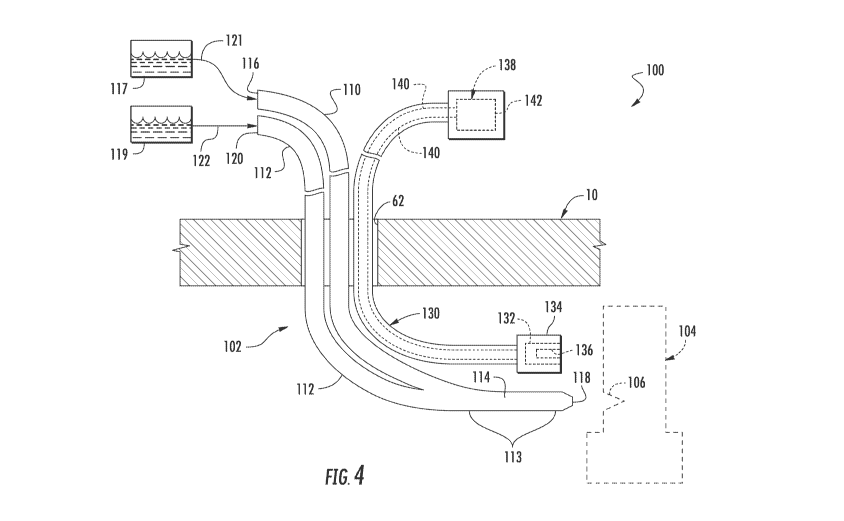
[0037] Referring now to FIGS. 4 and 5, simplified views of one embodiment
of a system 100
for performing an in situ repair of an internal component of a gas turbine
engine 10 are illustrated
in accordance with aspects of the present subject matter. The system 100 may
include a repair
tool 102 configured to be inserted within an interior of the gas turbine
engine 10to allow an in
situ repair procedure to be performed on an internal component(s) (indicated
by dashed lines 104
in FIG. 4) of the engine 10. More specifically, as shown in the embodiment
depicted in FIG. 4,
the repair tool 102 may be configured to be inserted through an access port 62
of the gas turbine
10, such as any of the access ports 62 described above with reference to FIGS.
1-3.
[0038] In general, the repair tool 102 may correspond to any suitable
tool(s) and/or
component(s) that may be inserted within the interior of the gas turbine
engine 10 to allow a
8
CA 03027708 2018-12-13
WO 2017/218385 PCT/US2017/036966
repair agent 124 (FIG. 5) to be supplied within the engine 10 for repairing an
identified defect
106 of the internal engine component(s) 104 being repaired (e.g., a turbine
blade(s)). For
example, as particularly shown in FIG. 5, the defect 106 corresponds to a
crack, void or other
defective area formed along the exterior of the component 104 that defines an
open or fillable
volume 108. As such, by supplying the repair agent 124 to the location of the
defect via the
repair tool 102, the fillable volume 108 may be filled-in with the repair
agent 124, thereby
repairing the defect 106.
[0039] In several embodiments, when the repair tool 102 is inserted within
the interior of the
gas turbine engine 10, the repair tool may define a mixing location 113 along
its length that is
positioned within the interior of the gas turbine engine 10. In such
embodiments, the repair tool
102 may be configured to supply separate constituent materials of the repair
agent 124 to the
mixing location 113 defined within the interior of the gas turbine engine 10.
For example, a first
constituent material 121 and a second constituent material 122 may be
transported via the repair
tool 102 from a location exterior to the gas turbine engine 10 to the mixing
location 113 within
the engine 10. At the mixing location 113, the first and second constituent
materials 121, 122
may be intermixed to form the repair agent 124, which may then be injected or
otherwise
directed into the fillable volume 108 defined by the defect 106 to repair the
internal component
104.
[0040] It should be appreciated that the first and second constituent
materials 121, 122 of the
repair agent 124 may generally correspond to any suitable material, such as
any suitable filler
material configured to "fill" the fillable volume 108 defined by the defect
106. For example, in
one embodiment, the first constituent material 121 may correspond to a resin,
and the second
constituent material 122 may correspond to a hardener. In such an embodiment,
the resin and
hardener may intermix at the mixing location 113 to form the repair agent 124,
such as by
forming an epoxy at the mixing location 113.
[0041] As shown in FIG. 4 , the repair tool 102 may generally extend
lengthwise between
first and second supply ends 116, 120 configured to be positioned outside the
gas turbine engine
and a tip end 118 configured to be positioned within the gas turbine engine
10. In several
embodiments, the repair tool 102 may include first and second conduits 110 and
112 for
transporting the first and second constituent materials 121, 122 from outside
the gas turbine
engine 10 to a corresponding mixing conduit 114 of the repair tool 102
extending from the
mixing location 113 within the gas turbine engine 10. For example, the first
conduit 110 may be
configured to extend from the first supply end 116 of the repair tool 102
through the access port
62 to the interior of the gas turbine engine 10 while the second conduit 112
may be configured to
extend from the second supply end 120 of the repair tool 102 through the
access port 62 to the
9
CA 03027708 2018-12-13
WO 2017/218385 PCT/US2017/036966
interior of the gas turbine engine 10. Additionally, as shown in FIGS. 4 and
5, the first and
second conduits 110, 112 may be configured to merge with one another within
the gas turbine
engine 10 at the mixing conduit 114 such that the mixing conduit 114 extends
from the merged
location of the first and second conduits 110, 112 to the tip end 118 of the
repair tool 102.
[0042] As shown in FIGS. 4 and 5, the first conduit 110 may be configured
to receive the
first constituent material 121 at the first supply end 116 of the repair tool
102 (e.g., from a
suitable material source 117) while the second conduit 112 may be configured
to receive the
second constituent material 122 at the second supply end 120 of the repair
tool 102 (e.g., from a
suitable material source 119). In such an embodiment, the first conduit 110
may deliver the first
constituent material 121 from the first supply end 116 to the mixing location
113 defined within
the mixing conduit 114, and the second conduit 112 may deliver the second
constituent material
122 from the second supply end 120 to the mixing location 113. Within the
mixing conduit 114,
the first and second constituent materials 121 and 122 may be intermixed to
form the repair agent
124.
[0043] It should be appreciated that the tip end 118 of the repair tool 102
may generally be
configured to be positioned adjacent to the location of the defect 106 for
directing the repair
agent 124 into the fillable volume 108. In several embodiments, the repair
tool 102 may also
include a nozzle 126 positioned at or adjacent to the tip end 118 of the
repair tool. In general, the
nozzle 126 may be configured to provide enhanced control of the direction of
the flow of the
repair agent 124 expelled from the repair tool 102. It should be appreciated
that, in one
embodiment, the nozzle 126 may be formed integrally with the mixing conduit
114.
Alternatively, the nozzle 126 may correspond to a separate component
configured to be
separately coupled to the mixing conduit 114.
[0044] Additionally, the system 100 may also include an optical probe 130
configured to be
used in association with the repair tool 102. For instance, as shown in FIG.
4, the optical probe
130 corresponds to a separate component configured to be used in combination
with the repair
tool 102 for repairing the defect 106. However, in other embodiments, the
optical probe 130
may be coupled to or integrated within the repair tool 102. Additionally, as
shown in FIG. 4, the
optical probe 130 may be inserted through the same access port 62 as the
repair tool 102.
However, in other embodiments, the optical probe 130 may be inserted into a
different access
port 62 than the repair tool 102, such as an access port 62 located adjacent
to the access port
within which the repair tool 102 has been inserted.
[0045] In general, the optical probe 130 may correspond to any suitable
optical device that
allows images of the interior of the engine 10 to be captured or otherwise
obtained. For instance,
in several embodiments, the optical probe 130 may correspond to a borescope,
videoscope,
CA 03027708 2018-12-13
WO 2017/218385 PCT/US2017/036966
fiberscope or any other similar optical device known in the art that allows
for the interior of a gas
turbine engine 10 to be viewed through an access port 62. In such embodiments,
the optical
probe 130 may include one or more optical elements (indicated schematically by
dashed box
132), such as one or more optical lenses, optical fibers, image capture
devices, cables, and/or the
like, for obtaining views or images of the interior of the gas turbine engine
10 at a tip 134 of the
probe 130 for transmitting or relaying such images from the probe tip 134
along the length of the
probe 130 to the exterior of the gas turbine engine 10 for viewing by the
personnel performing
the repair procedure on the internal component(s) 104. In addition, the probe
130 may include a
light source (indicated by dashed box 136) positioned at or adjacent to the
probe tip 134 to
provide lighting within the interior of the engine 10.
[0046] As shown in FIG. 4, the optical probe 130 may also include an
articulation assembly
138 that allows the orientation of the probe tip 134 to be adjusted within the
interior of the gas
turbine engine 10. For example, the articulation assembly 138 may allow for
the probe tip 134 to
be rotated or pivoted about a single axis or multiple axes to adjust the
orientation of the probe tip
134 relative to the remainder of the probe 130. It should be appreciated that
the articulation
assembly 138 may generally have any suitable configuration and/or may include
any suitable
components that allow for adjustment of the orientation of the probe tip 134
and one or more
articulation motors 142. In such an embodiment, by adjusting the tension of
cables 140 via
motor(s) 142, the probe tip 134 may be reoriented within the gas turbine
engine 10.
[0047] Referring now to FIG. 6, a variation of the embodiment of the repair
tool 102 shown
in FIG. 5 is illustrated in accordance with aspects of the present subject
matter. As shown, the
repair tool 102 may, in some embodiments, include a mixing element 150
positioned within the
mixing conduit 114. The mixing element 150 may be configured to urge the first
and second
constituent materials 121,122 to intermix with one another at the mixing
location 113 to form the
repair agent 124. As shown, the mixing element 150 may define a helical shape
and extend
along a length L of the mixing conduit 114 to promote intermixing of the first
and second
constituent materials 121, 122 throughout the mixing conduit 114. For example,
the mixing
element 150 may force the first and second constituent materials 121, 122
along a helically-
shaped travel path along the length L of the mixing conduit 114, thereby
facilitating intermixing
of the first and second constituent materials 121, 122 within the mixing
conduit 114 as such
constituent materials 121, 122 are supplied from the first and second conduits
110, 112 to the tip
end 118 of the repair tool 102. Further, in one embodiment, the outer
dimensions of the mixing
element 150 may be adapted to the inner dimensions of the mixing conduit 114
to ensure that the
first and second constituent materials 121, 122 cannot bypass the mixing
element 150. For
11
CA 03027708 2018-12-13
WO 2017/218385 PCT/US2017/036966
instance, the outer diameter of the mixing element 150 may be substantially
equal to the inner
diameter of the mixing conduit 114.
[0048] Referring now to FIGS. 7-9, simplified views of another embodiment
of a system 200
for performing an in situ repair of an internal component of a gas turbine
engine 10 is illustrated
in accordance with aspects of the present subject matter. The system 200 may
include a repair
tool 202 configured to be inserted within an interior of the gas turbine
engine to allow an in situ
repair procedure to be performed on an internal component(s) (indicated by
dashed lines 104 in
FIG. 7) of the gas turbine engine 10. More specifically, as shown in the
embodiment depicted in
FIG. 7, the repair tool 202 may be configured to be inserted through an access
port 62 of the gas
turbine 10, such as any of the access ports 62 described above with reference
to FIGS. 1-3.
[0049] Similar to the repair tool 102 described above, the repair tool 202
may be configured
to be inserted through an access port 62 of the gas turbine engine 10 to allow
a repair agent 224
(FIGS. 8 and 9) to be supplied within the gas turbine engine 10 for filling-in
a fillable volume
108 defined by an identified defect 106 formed in the internal component(s)
104 to be repaired
(e.g., turbine blade(s)). However, unlike the embodiment described above, the
repair tool 202 is
not configured to supply first and second constituent materials of the repair
agent 224 into the
interior of the gas turbine engine 10 via separate conduits of the repair tool
202. Instead, the
repair agent 224 may be pre-loaded into a mixing chamber 230 of the repair
tool 202, wherein the
mixing chamber 230 may define a mixing location 220 within the gas turbine 10.
More
specifically, the mixing location 220 of the repair tool 202 may, as shown in
FIGS 7-9, be
defined immediately upstream of its tip end 218. In such an embodiment, first
and second
constituents 225, 228 of the repair agent 224 may be continuously or
periodically intermixed
with one another within the mixing chamber 230 as the tip end 218 of the
repair tool 202 is being
positioned adjacent to the defect 106 of the internal engine component(s) 104.
[0050] As shown in FIGS. 8 and 9, the mixing chamber 230 of the repair tool
202 may, in
some embodiments, include an agitator 240 disposed therein. In one embodiment,
the agitator
240 may include an actuator 250 operatively coupled to a spring 260 extending
lengthwise
between a first end 262 and a second end 264. In addition, the agitator 240
may include a
plunger 270 attached to the second end 264 of the spring 260. In the
embodiment shown, the
plunger 270 is sized such that the plunger 270 may translate along a length L
of the chamber 230.
[0051] In operation, the agitator 240 may be configured to intermix two or
more constituent
materials of the repair agent 224, such as the first and second constituents
225, 228, by operating
the actuator 250 at a first vibratory or oscillatory rate in order to agitate
the constituent materials.
For example, in some embodiments, the actuator 250 may be an ultrasonic or
pneumatic mixing
driver configured to oscillate the plunger 270 (e.g., via the spring 260) at a
mixing rate ranging
12
CA 03027708 2018-12-13
WO 2017/218385 PCT/US2017/036966
from about 2 pounds per square inch (psi) to about 10 psi, such as from about
2 psi to about 8 psi,
or from about 2 psi to about 5 psi or from about 2 psi to about 4 psi and/or
any other subranges
therebetween. By oscillating the plunger 270 at the mixing rate, the various
constituents 225,
228 of the repair agent 224 may be agitated in a manner that results in the
constituents 225, 228
being intermixed with one another within the mixing chamber 250.
[0052] It should be appreciated that, in several embodiments, the actuator
250 may be
configured to receive electrical power from any suitable source. For instance,
in one
embodiment, the actuator 250 may receive electrical power from an articulation
assembly
(described below) of the repair tool 202. Alternatively, the actuator 250 may
be configured to
receive electrical power from an external source (not shown) via an electrical
conduit extending
between the external source and the actuator 250.
[0053] It should also be appreciated that, in several embodiments, the two
or more of the
constituents 225, 228 of the repair agent 224 may correspond to differently
sized aggregates. For
instance, in one embodiment, a cross-sectional area of the first constituent
225 may be greater
than a cross-sectional area of the second constituent 228. In another
embodiment, the cross-
sectional area of the first constituent 225 may be less than the cross-
sectional area of the second
constituent 228.
[0054] Further, in several embodiments, the actuator 250 may be configured
to oscillate the
plunger 270 (e.g., via the spring 260) at a second vibratory or oscillatory
rate that is higher than
the first mixing rate such that the spring 260 forces the plunger 270
outwardly away from the
actuator 250 along the length L of the chamber 230 towards the tip end 218 of
the repair tool 202
to allow the repair agent 224 to be expelled from the repair tool 202.
Additionally, the repair tool
202 may, optionally, include a cover 280 that is removably coupled to the tip
end 218 of the
repair tool 202. In such an embodiment, when the actuator 250 is operated so
as to oscillate the
plunger 270 at the second higher rate, a force may be generated through the
repair agent 224 that
is sufficient to push the cover 280 off of the tip end 218 of the repair tool
202, thereby allowing
the repair agent 224 to be expelled from the tip end 218.
[0055] As shown in FIG. 7, the repair tool 202 may also include an
articulation assembly 210
positioned at an exterior end 204 of the repair tool 202. In operation, the
articulation assembly
210 allows the orientation of the repair tool 202 to be adjusted within the
interior of the gas
turbine engine 10. For example, the articulation assembly 210 may allow for
the tip end 218 to
be rotated or pivoted about a single axis or multiple axes to adjust the
orientation of the tip end
218. It should be appreciated that the articulation assembly 210 may generally
have any suitable
configuration and/or may include any suitable components that allow for
adjustment of the
orientation of the tip end 218. For example, in one embodiment, a plurality of
articulation cables
13
CA 03027708 2018-12-13
WO 2017/218385 PCT/US2017/036966
212 may be coupled between the tip 218 and one or more articulation motors
214. In such an
embodiment, by adjusting the tension of the cables 212 via the motor(s) 214,
the tip end 218 may
be reoriented within the gas turbine engine 10.
[0056] Additionally, the system 200 may also include an optical probe 130
configured in
substantially the same manner as the optical probe 130 depicted in FIG. 4, and
accordingly, the
same or similar numbers may refer to the same or similar parts. For example,
the optical probe
130 may include one or more optical elements 132, a probe tip 134, an
articulation assembly 138,
articulation cables 140, and articulation motor(s) 142. Accordingly, the
optical probe 130 of
FIG. 7 may operate in substantially the same manner as described above for the
optical probe 130
of FIG. 4.
[0057] Referring now to FIG. 10, a flow diagram of one embodiment of a
method 300 for
performing an in situ repair of an internal component of a gas turbine engine
is illustrated in
accordance with aspects of the present subject matter. In general, the method
300 will be
discussed herein with reference to the gas turbine engine 10 and the systems
100, 200 described
above with reference to FIGS. 1-9. However, it should be appreciated by those
of ordinary skill
in the art that the disclosed method 300 may generally be implemented with gas
turbine engines
having any other suitable engine configuration and/or with systems having any
other suitable
system configuration. In addition, although FIG.10 depicts steps performed in
a particular order
for purposes of illustration and discussion, the methods discussed herein are
not limited to any
particular order or arrangement. One skilled in the art, using the disclosures
provided herein, will
appreciate that various steps of the methods disclosed herein can be omitted,
rearranged,
combined, and/or adapted in various ways without deviating from the scope of
the present
disclosure.
[0058] As shown in FIG. 10, at (302), the method 300 may include inserting
a repair tool
within an interior of the gas turbine engine. Specifically, in one embodiment,
the repair tool may
be inserted through an access port of the gas turbine engine such that a tip
end of the repair tool is
positioned within the interior of the gas turbine engine, and at least one
exterior end of the repair
tool is positioned outside the gas turbine engine. Additionally, at (304), the
method 300 may
include positioning the tip end of the repair tool adjacent to a defect of an
internal component of
the gas turbine engine. As indicated above, the defect may define a fillable
volume along a
portion of the internal component.
[0059] Moreover, at (306), the method 300 may include intermixing two or
more constituents
of a repair agent within the repair tool at a mixing location within the gas
turbine engine. For
example, as indicated above, the repair tool may, in one embodiment, include
first and second
conduits that extend into the gas turbine engine separately and merge within
the gas turbine at the
14
CA 03027708 2018-12-13
WO 2017/218385 PCT/US2017/036966
mixing location such that a first constituent material flowing through the
first conduit and a
second constituent material flowing through the second conduit merge at the
mixing location to
allow the first and second constituent materials to be intermixed to form the
repair agent. As
another example, the repair agent may be pre-loaded into a mixing chamber
positioned at the
mixing location. In such an embodiment, an agitator disposed within the mixing
chamber may
be configured to periodically or continuously intermix two or more
constituents of the repair
agent within the gas turbine engine.
[0060] Further, at (308), the method 300 may include expelling the repair
agent from the tip
end of the repair tool. In particular, the repair agent may be expelled in a
direction of the defect
of the internal component to at least partially fill the fillable volume with
the repair agent,
thereby allowing the defect to be repaired
[0061] This written description uses examples to disclose the invention,
including the
best mode, and also to enable any person skilled in the art to practice the
invention, including
making and using any devices or systems and performing any incorporated
methods. The
patentable scope of the invention is defined by the claims, and may include
other examples that
occur to those skilled in the art. Such other examples are intended to be
within the scope of the
claims if they include structural elements that do not differ from the literal
language of the
claims, or if they include equivalent structural elements with insubstantial
differences from the
literal languages of the claims.