Note: Descriptions are shown in the official language in which they were submitted.
0521710.0062
PATENT
1
SEALABLE CONTAINER
CROSS-REFERENCE TO RELATED APPLICATIONS
[0001] This application claims priority to U.S. Provisional Patent Application
Ser. No.
62/608,042, filed on December 20, 2017, the disclosure of which is hereby
incorporated by
reference in its entirety.
BACKGROUND
[0002] Containers, such as sacks, pouches, or bags, are generally used to hold
or store
objects. Containers may be used, for example, to package merchandise for
delivery to clients or
customers. Some containers include a closing or sealing mechanism that allows
the container to
be sealed or closed. Some known containers are closed, for example, using
twist ties, draw
strings, zipper-like self-closing features, adhesive strips, and/or heat
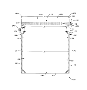
seals. At least some known
containers, however, are prone to leaking. It can be onerous and/or costly to
seal at least some
known containers in a leak-proof manner.
SUMMARY
[0003] Examples of the disclosure enable one or more containers to be sealed
in a leak-
proof, tamper-evident, and user-friendly manner. In one aspect, a sealable
container is provided.
The sealable container includes a first layer and a second layer coupled to
the first layer to define
a cavity therebetween. The second layer is coupled to the first layer at a
first side sector, a lower
sector, and a second side sector opposite the first side sector such that an
opening in fluid
communication with the cavity is defined between the first layer and the
second layer at an upper
sector opposite the lower sector. The second layer includes a flap portion at
the upper sector
extending beyond an upper edge of the first layer. A first coupling mechanism
is coupled to an
inner surface of the second layer generally facing the first layer at the
upper sector, and a second
coupling mechanism is coupled to an outer surface of the second layer
generally facing away
from the first layer at the upper sector.
[0004] In another aspect, a sealable container is provided. The sealable
container
includes a first layer and a second layer coupled to the first layer to define
a cavity there
between. The second layer is coupled to the first layer at a first side
sector, a lower sector, and a
second side sector opposite the first side sector such that an opening in
fluid communication with
CA 3028204 2018-12-20
0521710.0062
PATENT
2
the cavity is defined between the first layer and the second layer at an upper
sector opposite the
lower sector. The second layer includes a flap portion at the upper sector
extending beyond an
upper edge of the first layer. In some embodiments, a coupling mechanism is
coupled to an inner
surface of the second layer generally facing the first layer at the upper
sector. In some
embodiments, a coupling mechanism is coupled to an outer surface of the second
layer generally
facing away from the first layer at the upper sector.
[0005] In another aspect, a method is provided for manufacturing a sealable
container.
The method includes extending a front layer at a first level and a rear layer
at a second level. The
rear layer includes a flap portion extending beyond an upper edge of the front
layer. The rear
layer is coupled to the front layer to define a cavity and an opening in fluid
communication with
the cavity between the front layer and the rear layer. The opening is at an
upper sector. A first
coupling mechanism is coupled to an anterior surface of the rear layer at the
upper sector, and a
second coupling mechanism is coupled to a posterior surface of the rear layer
at the upper sector.
[0006] In another aspect, a method is provided for manufacturing a sealable
container.
The method includes extending a front layer at a first level and a rear layer
at a second level. The
rear layer includes a flap portion extending beyond an upper edge of the front
layer. The rear
layer is coupled to the front layer to define a cavity and an opening in fluid
communication with
the cavity between the front layer and the rear layer. The opening is at an
upper sector. A
coupling mechanism is coupled to one of an anterior surface of the rear layer
at the upper sector
or a posterior surface of the rear layer at the upper sector.
[0007] In yet another aspect, a method is provided for using a sealable
container to
contain one or more objects. The method includes using a first coupling
mechanism at an upper
sector to couple an anterior surface of a rear flap to a posterior surface of
a front flap. The front
flap and the rear flap include a pair of lateral portions and a pair of tab
portions extending
laterally from the pair of lateral portions. The rear flap includes an
overhang portion extending
upwardly beyond an upper edge of the front flap. The pair of tabs are folded
medially to couple
the anterior surface of the rear flap to itself. The overhang portion is
folded downwardly to
couple the anterior surface of the rear flap to an anterior surface of the
front flap. A second
coupling mechanism at the upper sector is used to couple the posterior surface
of the rear flap to
an anterior surface of the sealable container below the front flap.
[0008] In yet another aspect, a method is provided for using a sealable
container to
CA 3028204 2018-12-20
0521710.0062
PATENT
3
contain one or more objects. The method includes using a coupling mechanism at
an upper
sector to couple one of an anterior surface of a rear flap to a posterior
surface of a front flap or an
upper sector to couple the posterior surface of the rear flap to an anterior
surface of the sealable
container below the front flap. The front flap and the rear flap include a
pair of lateral portions
and a pair of tab portions extending laterally from the pair of lateral
portions. The rear flap
includes an overhang portion extending upwardly beyond an upper edge of the
front flap. The
pair of tabs are folded medially to couple the anterior surface of the rear
flap to itself. The
overhang portion is folded downwardly to couple the anterior surface of the
rear flap to an
anterior surface of the front flap.
[0009] This Summary is provided to introduce a selection of concepts in a
simplified
form that are further described below in the Detailed Description. This
Summary is not intended
to identify key features or essential features of the claimed subject matter,
nor is it intended to be
used as an aid in determining the scope of the claimed subject matter.
BRIEF DESCRIPTION OF THE DRAWINGS
[0010] FIG. 1 includes a front view of an example sealable container.
[0011] FIG. 2 includes a front view of an example layer that may be used with
a
container, such as the sealable container shown in FIG. 1.
[0012] FIG. 3 includes a front view of another example layer that may be used
with a
container, such as the sealable container shown in FIG. 1.
[0013] FIG. 4 includes a rear view of the layer shown in FIG. 3.
[0014] FIG. 5 includes a side view of the layers shown in FIGS. 2 and 3.
[0015] FIG. 6 includes a flowchart of an example method of manufacturing a
container,
such as the sealable container shown in FIG. 1.
[0016] FIG. 7 includes a flowchart of an example method of using a container,
such as
the sealable container shown in FIG. 1.
[0017] FIGs. 8-11 include detailed schematic views of an example sealing
system that
may be used with a container, such as the sealable container shown in FIG. 1,
in various states.
CA 3028204 2018-12-20
0521710.0062
PATENT
4
[0018] Corresponding reference characters indicate corresponding parts
throughout the
drawings. Although specific features may be shown in some of the drawings and
not in others,
this is for convenience only. In accordance with the examples described
herein, any feature of a
drawing may be referenced and/or claimed in combination with any feature of
any other
drawing.
DETAILED DESCRIPTION
[0019] The present disclosure relates to containers and, more particularly, to
a leak-
proof sealable container. Examples described herein include one or more panels
arranged in
multiple layers to define a cavity. Exemplary containers include a panel that
includes a flap that
has a coupling mechanism on each side of it such that one of the coupling
mechanisms (e.g., the
inner coupling mechanism) is between the layers. Other exemplary containers
include a panel
that includes a flap that has a single coupling mechanism on one side of it.
An upper sector
includes laterally-extending tabs that are foldable to facilitate keeping
liquids inside the
container. In this manner, the examples described herein enable a user to
effectively and/or
efficiently seal a container in a leak-proof manner.
[0020] In at least some examples, the container includes a first layer and a
second layer
coupled to the first layer to define a cavity between the first layer and the
second layer. The
second layer is coupled to the first layer along the side edges and along the
lower edge such that
there is an opening at the upper sector (e.g., proximate the upper edge of the
first layer and/or
second layer). The second layer includes a flap portion at the upper sector
that extends beyond an
upper edge of the first layer. A first coupling mechanism is coupled to an
inner surface of the
second layer, and a second coupling mechanism is coupled to an outer surface
of the second
layer. While the examples described herein are described using a rectangular-
shaped container,
one of ordinary skill in the art would understand and appreciate that the
container may have any
shape that enables a user to seal the container as described herein.
[0021] FIG. 1 shows an example sealable pouch, bag, and/or container 100. The
container 100 includes a first layer 110 and a second layer 120 coupled to the
first layer 110.
FIG. 2 shows a front view of the first layer 110. FIG. 3 shows a front view of
the second layer
120. FIG. 4 shows a rear view of the second layer 120. FIG. 5 includes a side
view of the first
layer 110 and the second layer 120. The first layer 110 and/or second layer
120 may be
fabricated, for example, from one or more liquid-impermeable, odor-
neutralizing, and/or
CA 3028204 2018-12-20
0521710.0062
PATENT
antibacterial materials. For example, the first layer 110 and/or second layer
120 may include a
plastic film material. In this manner, the first layer 110 and/or second layer
120 may be used to
prevent or restrict at least some liquid (e.g., water) from passing through
the first layer 110
and/or second layer 120. Additionally or alternatively, at least a portion of
the first layer 110
and/or second layer 120 may be fabricated from a breathable material that
allows at least some
gas (e.g., air) to pass through the first layer 110 and/or second layer 120.
[0022] The second layer 120 may be coupled to the first layer 110 to define a
cavity
between the first layer 110 and the second layer 120. One or more objects may
be contained in
the cavity between the first layer 110 and the second layer 120. The second
layer 120 may be
coupled to the first layer 110, for example, at a first side sector 122, a
lower sector 124, and a
second side sector 126 opposite the first side sector such that an opening in
fluid communication
with the cavity is defined between the first layer 110 and the second layer
120 at an upper sector
128 opposite the lower sector 124. In some examples, the second layer 120 is
coupled to the first
layer 110 along a right edge 132 of the first layer 110 and/or second layer
120, along a lower
edge 134 of the first layer 110 and/or second layer 120, and/or along a left
edge 136 of the first
layer 110 and/or second layer 120 while an upper edge 138 of the first layer
110 is free from an
upper edge 139 of the second layer 120. The second layer 120 may be coupled to
the first layer
110 using one or more side seals 140, for example. Alternatively, the second
layer 120 may be
coupled to the first layer 110 using any closing or sealing mechanism that
enables the container
100 to be sealed as described herein.
[0023] The first layer 110 includes a first flap portion 142 at the upper
sector 128, and
the second layer 120 includes a second flap portion 144 at the upper sector
128. The first flap
portion 142 is free from the second layer 120 and/or the second flap portion
144 is free from the
first layer 110 along the right edge 132, left edge 136, and/or upper edge
138. In some examples,
the first flap portion 142 extends vertically a first height 146 from an upper
edge 147 of the side
seal 140, and the second flap portion 144 extends vertically a second height
148 greater than the
first height 146 from the upper edge 147 of the side seal 140. That is, the
second flap portion 144
may extend beyond an upper edge 138 of the first layer 110 (e.g., first flap
portion 142). In some
examples, the second height 148 is approximately twice the first height 146.
For example, the
first height 146 may be approximately 0.25-1.25 inches (in.), and the second
height 148 may be
approximately 0.50-2.50 in. In one example, the first height 146 is 1.0 in.,
and second height 148
is 2.0 in. Alternatively, the first flap portion 142 and/or second flap
portion 144 may have any
CA 3028204 2018-12-20
0521710.0062
PATENT
6
height that enables the container 100 to be sealed as described herein.
[0024] A first coupling mechanism 150 is coupled to an anterior or inner
surface of the
second layer 120 at the upper sector 128, and a second coupling mechanism 152
is coupled to a
posterior or outer surface of the second layer 120 at the upper sector 128.
The inner surface of
the second layer 120 faces forward, generally toward the first layer 110, and
the outer surface of
the second layer 120 faces rearward, generally away from the first layer 110.
In some examples,
the first coupling mechanism 150 and/or second coupling mechanism 152 extend
horizontally
substantially across a width 154 of the container 100 at the upper sector 128
(an "upper width").
[0025] In some examples, the first coupling mechanism 150 extends vertically a
first
height 156 from the upper edge 147 of the side seal 140, and the second
coupling mechanism
152 extends vertically a second height 158 less than the first height 156 from
the upper edge 147
of the side seal 140. That is, the second coupling mechanism 152 may be
smaller in area than the
first coupling mechanism 150. In some examples, the first height 156 is
substantially similar or
equal to the second height 148 (i.e., the height of the second flap portion
144), and/or the second
height 158 is substantially similar or equal to the first height 146 (i.e.,
the height of the first flap
portion 142). For example, the first height 156 may be approximately 0.50-2.50
in., and the
second height 158 may be approximately 0.25-1.25 in. In one example, the first
height 156 is 2.0
in., and the second height 158 is 1.0 in. Alternatively, the first coupling
mechanism 150 and/or
second coupling mechanism 152 may have any height that enables the container
100 to be sealed
as described herein. For example, the first coupling mechanism 150 may be
spaced a first
distance from the upper edge 139 of the second layer 120 (e.g., the first
height 156 may be less
than the second height 148), and/or the second coupling mechanism 152 may be
spaced a second
distance greater than the first distance from the upper edge 139 of the second
layer 120 (e.g., the
second height 158 may be less than the first height 146).
[0026] As shown in FIG. 5, the first coupling mechanism 150 includes one of
more first
adhesive strips coupled to an anterior surface of the second flap portion 144,
and the second
coupling mechanism 152 includes one or more second adhesive strips coupled to
a posterior
surface of the second flap portion 144. In some examples, the first coupling
mechanism 150 can
be an elongated interference fit (also known as a friction fit or press fit),
which enables to
container 100 to be sealed when the interference fit is pressed together. The
first coupling
mechanism 150 extends between the first layer 110 and second layer 120. In
this manner, the
container 100 may be at least partially closed or sealed using the first
coupling mechanism 150.
CA 3028204 2018-12-20
0521710.0062
PATENT
7
In some examples, the first coupling mechanism 150 and/or second coupling
mechanism 152
include one or more release liners 159 (shown in FIG. 5) extended across the
first adhesive strip
and/or second adhesive strip, respectively. The release liners 159 are
detachably coupled to the
first adhesive strip and/or second adhesive strip.
[0027] The container 100 includes one or more tabs 160 at the upper sector
128. The
tabs 160 may extend laterally outward from a core section 162 between the tabs
160 at the first
side sector 122 and/or second side sector 126. The tabs 160 may extend
laterally outward from a
respective lateral portion of the core section 162, for example, a width 164
of approximately
0.50-1.00 in. Alternatively, one or more tabs 160 may extend laterally outward
from the core
section 162 any width that enables the container 100 to be sealed as described
herein.
[0028] One or more side seals 140 may extend at least partially along a lower
edge 166
of the tabs 160. That is, the second layer 120 may be coupled to the first
layer 110 at least
partially along the lower edge 166. In some examples, the side seals 140
extend vertically a
height 168 of approximately 0.125-0.375 in. Alternatively, the side seals 140
may have any
height at the lower edge 166 of the tabs 160 that enables the container 100 to
be sealed as
described herein.
[0029] The container 100 includes a midsection 170 between the lower sector
124 and
the upper sector 128. The midsection 170 includes a first cutout portion 172
at the first side
sector 122 and a second cutout portion 174 at the second side sector 126. The
first cutout portion
172 and/or second cutout portion 174 may define one or more zones 176 between
the tabs 160 at
the upper sector 128 and a "body" of the container 100 at the lower sector
124. One or more
portions of the first layer 110 and/or a second layer 120 may be removed from
the zones 176, for
example, to form the first cutout portion 172 and/or second cutout portion 174
at the midsection
170 and/or one or more tabs 160 at the upper sector 128. In this manner, the
container 100 may
extend horizontally a middle width 178 at the midsection 170 that is less than
the upper width
154. The middle width 178 may also be less than a width 180 of the container
100 at the lower
sector 124 (a "lower width"). In some examples, the lower width 180 is
substantially similar or
equal to the upper width 154.
[0030] One or more side seals 140 at the first cutout portion 172 and/or
second cutout
portion 174 may have a J-shaped configuration including a linear segment and a
curved segment.
In some examples, the linear segment extends vertically a height 182 greater
than the second
CA 3028204 2018-12-20
0521710.0062
PATENT
8
height 148 (i.e., the height of the second flap portion 144). For example, the
height 182 may be
approximately 0.75-3.00 in. Alternatively, the linear segment of the side
seals 140 at the first
cutout portion 172 and/or second cutout portion 174 may have any height that
enables the
container 100 to be sealed as described herein.
[0031] In some examples, the container 100 includes a first tear notch portion
192 at
the first side sector 122 and a second tear notch portion 194 at the second
side sector 126. The
first tear notch portion 192 and/or second tear notch portion 194 may have one
or more lines of
weakness or notches 196 defined therein. One or more portions of the first
layer 110 and/or a
second layer 120 may be removed from the notches 196, for example, to form the
first tear notch
portion 192 and/or second tear notch portion 194.
[0032] FIG. 6 shows operations of a method 200 of manufacturing the container
100.
At operation 210, a front layer (e.g., first layer 110) is extended at a first
level, and a rear layer
(e.g., second layer 120) is extended at a second level. The front layer and/or
rear layer are
extended such that a rear flap (e.g., second flap portion 144) extends beyond
an upper edge of the
front layer (e.g., upper edge 138). In some examples, a single panel is folded
such that one
section of the sheet extends at the first level (e.g., the front layer) and
another section of the sheet
extends at the second level (e.g., the rear layer). The single panel may be
folded, for example, so
that the rear layer is coupled to the front layer along a lower edge at a
lower sector (e.g., lower
sector 124). That is, the lower edge of the front layer and rear layer may be
a fold edge.
Alternatively, one sheet extending at the first level (e.g., the front layer)
may be coupled to
another sheet extending at a second level (e.g., the rear layer).
[0033] One or more portions (e.g., zones 176) may be removed from the front
layer
and/or rear layer to form a first cutout portion (e.g., first cutout portion
172) at a first side sector
(e.g., first side sector 122) and a first laterally-extending tab (e.g., tab
160) at an upper sector
(e.g., upper sector 128), and/or to form a second cutout portion (e.g., second
cutout portion 174)
at a second side sector opposite the first side sector (e.g., second side
sector 126) and a second
laterally-extending tab opposite the first laterally-extending tab (e.g., tab
160) at the upper sector.
The portions may be cut, for example, using a die cutting press.
[0034] At operation 220, the rear layer is coupled to the front layer to
define a cavity
and an opening in fluid communication with the cavity between the front layer
and the rear layer.
The rear layer may be coupled to the front layer, for example, using a heat
seal press. In some
CA 3028204 2018-12-20
0521710.0062
PATENT
9
examples, the front layer and/or rear layer may be sealed along one or more
side edges (e.g.,
right edge 132, left edge 136), including at a midsection (e.g., midsection
170), and/or along one
or more lower edges at the upper sector (e.g., lower edge 166) such that the
opening is defined at
the upper sector. In some examples, the rear layer is coupled to the front
layer such that the front
layer includes another flap portion (e.g., first flap portion 142). The flap
portion included in the
front layer may have a flap height (e.g., first height 146), for example, that
is less than a flap
height of the flap portion included in the rear layer (e.g., second height
148).
[0035] A first coupling mechanism (e.g., first coupling mechanism 150) is
coupled to
an anterior surface of the rear layer at the upper sector at operation 230.
The first coupling
mechanism may be coupled to the anterior surface of the rear layer, for
example, such that the
first coupling mechanism has a coupling mechanism height (e.g., first height
156) that is
substantially equal to the flap height of the front layer. In some examples,
the first coupling
mechanism is spaced a first distance from an upper edge of the rear layer
(e.g., upper edge 139).
[0036] A second coupling mechanism (e.g., second coupling mechanism 152) to a
posterior surface of the rear layer at the upper sector at operation 240. The
second coupling
mechanism may be coupled to the posterior surface of the rear layer, for
example, such that the
second coupling mechanism has a coupling mechanism height (e.g., second height
158) that is
less than that of the first coupling mechanism. In some examples, the second
coupling
mechanism is spaced a second distance from the upper edge of the rear layer
that is greater than
the first distance.
[0037] In some examples, the midsection is identified, and one or more
portions of the
front layer and/or rear layer (e.g., notches 196) are removed to form one or
more tear notch
portions (e.g., first tear notch portion 192, second tear notch portion 194)
below the midsection.
For example, a first portion may be removed to form a first tear notch portion
at the first side
sector, and/or a second portion may be removed to form a second tear notch
portion at the second
side sector.
[0038] FIG. 7 shows operations of a method 300 of using the container 100.
FIGs. 8-11
show the container 100 after various operations of the method 300. At
operation 310, a first
coupling mechanism (e.g., first coupling mechanism 150) at an upper sector
(e.g., upper sector
128) is used to couple an anterior surface of a rear flap (e.g., second flap
portion 144) to a
posterior surface of a front flap (e.g., first flap portion 142). In some
examples, one or more
CA 3028204 2018-12-20
0521710.0062
PATENT
release liners (e.g., release liner 159) are detached or uncoupled from the
first coupling
mechanism to expose the first coupling mechanism for coupling the anterior
surface of the rear
flap to the posterior surface of the front flap. FIG. 8 shows the container
100 after operation 310.
[0039] At operation 320, one or more tab portions of the rear flap and/or the
front flap
(e.g., tab 160) are folded inwardly (e.g., in a medial direction) to couple
the anterior surface of
the rear flap and/or front flap to itself (i.e., one area of the anterior
surface is coupled to another
area of the anterior surface). In some examples, a right tab portion extending
rightward from a
right lateral portion (e.g., at the core section 162) is folded in a leftward
direction so that its
anterior surface is re-oriented to face the anterior surface of the right
lateral portion, and/or a left
tab portion extending leftward from a left lateral portion (e.g., at the core
section 162) is folded
in a rightward direction so that its anterior surface is re-oriented to face
the anterior surface of
the left lateral portion. The tab portions may be securely coupled or secured
to the lateral
portions, for example, using the first coupling mechanism.
[0040] At operation 330, an overhang portion of the rear flap (e.g., a portion
of the rear
flap extending upwardly beyond the upper edge 138 of the front flap) is folded
downwardly over
the top (e.g., upper edge 138) of the front flap to couple the anterior
surface of the rear flap to an
anterior surface of the front flap. In some examples, the overhang portion is
folded in a
downward direction so that its anterior surface is re-oriented to face the
anterior surface of the
front flap. The overhang portion may be securely coupled or secured to the
front flap, for
example, using the first coupling mechanism. FIG. 9 shows the container 100
after operation
330.
[0041] At operation 340, a second coupling mechanism (e.g., second coupling
mechanism 152) at the upper sector is used to couple the posterior surface of
the rear flap to an
anterior surface of the container 100 below the front flap. For example, the
rear flap may be
coupled to one or more cutout portions (e.g., first cutout portion 172, second
cutout portion 174)
at the midsection (e.g., midsection 170). In some examples, one or more
release liners (e.g.,
release liner 159) are detached or uncoupled from the second coupling
mechanism to expose the
second coupling mechanism for coupling the posterior surface of the rear flap
to the anterior
surface of the cutout portions. FIG. 11 shows the container 100 after
operation 340.
[0042] In some examples, the second coupling mechanism is spaced from the
upper
edge of the rear layer (e.g., upper edge 139) such that the posterior surface
of the overhang
CA 3028204 2018-12-20
0521710.0062
PATENT
11
portion is free from the second coupling mechanism. That is, the second
coupling mechanism
may have a height (e.g., second height 158) that is substantially similar to,
equal to, or less than a
height of the front flap (e.g., first height 146), and/or have an elevation
(i.e., a height from the
lower edge of the front layer and/or rear layer) that is substantially similar
to, equal to, or less
than an elevation of the front flap. In this manner, the second coupling
mechanism may be
desirably positioned by making successive folds or rolling the overhang
portion in a downward
direction. For example, after the overhang portion is brought over the front
flap at operation 330,
the second coupling mechanism may face rearward at an upper elevation of the
container 100.
FIG. 9 shows the container 100 after one fold of the overhang portion. On the
next (e.g., second)
fold of the overhang portion, the second coupling mechanism may be brought
over the top and
re-oriented to face forward at a new upper elevation of the container 100.
FIG. 10 shows the
container 100 after two folds of the overhang portion. And, on the next (e.g.,
third) fold of the
overhang portion, the second coupling mechanism may be tucked in under the
fold and re-
oriented to face the anterior surface of the cutout portions to couple the
rear flap to the cutout
portions. FIG. 11 shows the container 100 after three folds of the overhang
portion.
[0043] In at least some examples, the container includes a first layer and a
second layer
coupled to the first layer to define a cavity between the first layer and the
second layer. The
second layer is coupled to the first layer along the side edges and along the
lower edge such that
there is an opening at the upper sector (e.g., proximate the upper edge of the
first layer and/or
second layer). The second layer includes a flap portion at the upper sector
that extends beyond an
upper edge of the first layer. In some embodiments, a coupling mechanism is
coupled to an inner
surface of the second layer. In other embodiments, a coupling mechanism is
coupled to an outer
surface of the second layer. While the examples described herein are described
using a
rectangular-shaped container, one of ordinary skill in the art would
understand and appreciate
that the container may have any shape that enables a user to seal the
container as described
herein.
[0044] As described herein, the first layer and/or second layer may be
fabricated, for
example, from one or more liquid-impermeable, odor-neutralizing, and/or
antibacterial materials.
For example, the first layer and/or second layer may include a plastic film
material. In this
manner, the first layer and/or second layer may be used to prevent or restrict
at least some liquid
(e.g., water) from passing through the first layer and/or second layer.
Additionally or
alternatively, at least a portion of the first layer and/or second layer may
be fabricated from a
CA 3028204 2018-12-20
0521710.0062
PATENT
12
breathable material that allows at least some gas (e.g., air) to pass through
the first layer and/or
second layer.
[0045] As described herein, the second layer may be coupled to the first layer
to define
a cavity between the first layer and the second layer. One or more objects may
be contained in
the cavity between the first layer and the second layer. The second layer may
be coupled to the
first layer, for example, at a first side sector, a lower sector, and a second
side sector opposite the
first side sector such that an opening in fluid communication with the cavity
is defined between
the first layer and the second layer at an upper sector opposite the lower
sector. In some
examples, the second layer is coupled to the first layer along a right edge of
the first layer and/or
second layer, along a lower edge of the first layer and/or second layer,
and/or along a left edge of
the first layer and/or second layer while an upper edge of the first layer is
free from an upper
edge of the second layer. The second layer may be coupled to the first layer
using one or more
side seals, for example. Alternatively, the second layer may be coupled to the
first layer using
any closing or sealing mechanism that enables the container to be sealed as
described herein.
[0046] As described herein, the first layer includes a first flap portion at
the upper
sector, and the second layer includes a second flap portion at the upper
sector. The first flap
portion is free from the second layer and/or the second flap portion is free
from the first layer
along the right edge, left edge, and/or upper edge. In some examples, the
first flap portion
extends vertically a first height from an upper edge of the side seal, and the
second flap portion
extends vertically a second height greater than the first height from the
upper edge of the side
seal. That is, the second flap portion may extend beyond an upper edge of the
first layer (e.g.,
first flap portion). In some examples, the second height is approximately
twice the first height.
For example, the first height may be approximately 0.25-1.25 inches (in.), and
the second height
may be approximately 0.50-2.50 in. In one example, the first height is 1.0
in., and second height
is 2.0 in. Alternatively, the first flap portion and/or second flap portion
may have any height that
enables the container to be sealed as described herein.
[0047] Some example containers include a coupling mechanism 150 is coupled to
an
anterior or inner surface of the second layer at the upper sector. Some
example containers
include a coupling mechanism coupled to a posterior or outer surface of the
second layer at the
upper sector. The inner surface of the second layer faces forward, generally
toward the first
layer, and the outer surface of the second layer faces rearward, generally
away from the first
layer. In some examples, the coupling mechanism extends horizontally
substantially across a
CA 3028204 2018-12-20
0521710.0062
PATENT
13
width of the container at the upper sector (an "upper width"). Some example
containers include
an elongated interference fit (also known as a friction fit or press fit),
which enables to container
100 to be sealed when the interference fit is pressed together.
[0048] In some example containers, the coupling mechanism extends vertically a
first
height from the upper edge of the side seal. In some example containers, the
coupling
mechanism extends vertically a second height less than the first height from
the upper edge of
the side seal. Alternatively, the coupling mechanism may have any height that
enables the
container to be sealed as described herein. For example, the coupling
mechanism may be spaced
a first distance from the upper edge of the second layer (e.g., the first
height may be less than the
second height), and/or the coupling mechanism may be spaced a second distance
greater than the
first distance from the upper edge of the second layer (e.g., the second
height may be less than
the first height). In some example containers, the coupling mechanism can be
combined with an
elongated interference fit (also known as a friction fit or press fit), which
enables to container
100 to be sealed when the interference fit is pressed together, and further
sealed as described
herein.
[0049] The coupling mechanism includes one of more adhesive strips coupled to
an
anterior surface of the second flap portion. Alternatively, the coupling
mechanism includes one
or more adhesive strips coupled to a posterior surface of the second flap
portion. The coupling
mechanism extends between the first layer and second layer. In this manner,
the container may
be at least partially closed or sealed using the coupling mechanism. In some
example containers,
the coupling mechanism can be combined with an elongated interference fit
(also known as a
friction fit or press fit), which enables to container 100 to be sealed when
the interference fit is
pressed together. In some examples, the coupling mechanism includes one or
more release liners
extended across the adhesive strip. The release liners are detachably coupled
to the adhesive
strip.
[0050] As described herein, the container includes one or more tabs at the
upper sector.
The tabs may extend laterally outward from a core section between the tabs at
the first side
sector and/or second side sector. The tabs may extend laterally outward from a
respective lateral
portion of the core section for any width that enables the container to be
sealed as described
herein.
[0051] As described herein, one or more side seals may extend at least
partially along a
CA 3028204 2018-12-20
0521710.0062
PATENT
14
lower edge of the tabs. That is, the second layer may be coupled to the first
layer at least partially
along the lower edge. The side seals may have any height at the lower edge of
the tabs that
enables the container to be sealed as described herein.
[0052] As described herein, the container includes a midsection between the
lower
sector and the upper sector. The midsection includes a first cutout portion at
the first side sector
and a second cutout portion at the second side sector. The first cutout
portion and/or second
cutout portion may define one or more zones between the tabs at the upper
sector and a "body"
of the container at the lower sector. One or more portions of the first layer
and/or a second layer
may be removed from the zones, for example, to form the first cutout portion
and/or second
cutout portion at the midsection and/or one or more tabs at the upper sector.
In this manner, the
container may extend horizontally a middle width at the midsection that is
less than the upper
width. The middle width may also be less than a width of the container at the
lower sector (a
"lower width"). In some examples, the lower width is substantially similar or
equal to the upper
width.
[0053] As described herein, one or more side seals at the first cutout portion
and/or
second cutout portion may have a J-shaped configuration including a linear
segment and a
curved segment. In some examples, the linear segment extends vertically a
height greater than
the second height (i.e., the height of the second flap portion).
Alternatively, the linear segment of
the side seals at the first cutout portion and/or second cutout portion may
have any height that
enables the container to be sealed as described herein.
[0054] As described herein, in some examples, the container includes a first
tear notch
portion at the first side sector and a second tear notch portion at the second
side sector. The first
tear notch portion and/or second tear notch portion may have one or more lines
of weakness or
notches defined therein. One or more portions of the first layer and/or a
second layer may be
removed from the notches, for example, to form the first tear notch portion
and/or second tear
notch portion.
[0055] Example containers are described herein and illustrated in the
accompanying
drawings. The examples described herein provide a container that is sealable
in a leak-proof,
tamper-evident, and user-friendly manner. The cavity may be accessed, for
example, by tearing
the container 100 (e.g., at the notches 196). This written description uses
examples to disclose
aspects of the disclosure and also to enable a person skilled in the art to
practice the aspects,
CA 3028204 2018-12-20
=
0521710.0062
PATENT
including making or using the above-described systems and executing or
performing the above-
described methods. For example, the examples described herein include a
sealable closure
including a panel or flap having an adhesive on both sides of the flap.
Additionally, the examples
described herein include a container with cutouts forming tabs that do not
extend wider than the
rest of the container and tear notches below the cutouts.
[0056] Having described aspects of the disclosure in terms of various examples
with
their associated operations, it will be apparent that modifications and
variations are possible
without departing from the scope of the disclosure as defined in the appended
claims. That is,
aspects of the disclosure are not limited to the specific examples described
herein, and all matter
contained in the above description and shown in the accompanying drawings
shall be interpreted
as illustrative and not in a limiting sense. For example, the examples
described herein may be
implemented and utilized in connection with many other applications such as,
but not limited to,
sacks, pouches, and/or bags.
[0057] Components of the systems and/or operations of the methods described
herein
may be utilized independently and separately from other components and/or
operations described
herein. Moreover, the methods described herein may include additional or fewer
operations than
those disclosed, and the order of execution or performance of the operations
described herein is
not essential unless otherwise specified. That is, the operations may be
executed or performed in
any order, unless otherwise specified, and it is contemplated that executing
or performing a
particular operation before, contemporaneously with, or after another
operation is within the
scope of the disclosure. Although specific features of various examples of the
disclosure may be
shown in some drawings and not in others, this is for convenience only. In
accordance with the
principles of the disclosure, any feature of a drawing may be referenced
and/or claimed in
combination with any feature of any other drawing.
[0058] When introducing elements of the disclosure or the examples thereof,
the
articles "a," "an," "the," and "said" are intended to mean that there are one
or more of the
elements. References to an "embodiment" or an "example" of the present
disclosure are not
intended to be interpreted as excluding the existence of additional
embodiments or examples that
also incorporate the recited features. The terms "comprising," "including,"
and "having" are
intended to be inclusive and mean that there may be elements other than the
listed elements. The
phrase "one or more of the following: A, B, and C" means "at least one of A
and/or at least one
of B and/or at least one of C."
CA 3028204 2018-12-20
=
0521710.0062
PATENT
16
[0059] The patentable scope of the invention is defined by the claims, and may
include
other examples that occur to those skilled in the art. Such other examples are
intended to be
within the scope of the claims if they have structural elements that do not
differ from the literal
language of the claims, or if they include equivalent structural elements with
insubstantial
differences from the literal language of the claims.
CA 3028204 2018-12-20