Note: Descriptions are shown in the official language in which they were submitted.
CA 03029164 2018-12-21
WO 2018/007631 PCT/EP2017/067168
1
Hearing Test and Modification of Audio Signals
Field
This disclosure relates to a hearing test. This disclosure also relates to the
modification of
audio signals, for example speech and music, using results of the hearing
test. It is particularly suitable
for, but by no means limited to, enhancement of audio signals for people with
addressable hearing loss
or needs, in particular over a communications network such as a mobile
telephone network.
Background
The current solutions for enhanced audio over a mobile or fixed device, for
example a mobile or
landline phone, provide software applications that can be loaded into or
implemented by typical user
devices to simulate a hearing aid on a mobile or fixed terminal, for example
by making use of digital
technology to use local processing at the user device to emulate a hearing aid
for people with mild to
severe hearing loss, but not for the case of profound to extreme hearing loss
that may require specialist
treatment or medical solution. Other solutions provide complex device
accessories as add-ons to a
mobile device by way of replacing or working in combination with a hearing aid
or implant for people
with mild to severe hearing loss.
Such solutions require processing power at the user device and/or additional
hardware or
firmware.
Accordingly, there is a need for providing the convenience of audio
enhancement carried out
by a central system, for example at the network level, such that the
enhancement is transparent to a user
device and can therefore be implemented or provided on or to any user device
(which may be mobile,
fixed or a stand alone speaker or other such communication method), and not
restricted to higher end
devices with greater processing power and local resources. Further, avoiding
the need for device
accessories may increases audio enhancement availability for more users as
hardware or firmware
requirements are reduced, implementation costs and energy use may be lower,
hence potentially
allowing audio enhancement to reach a wider range of users.
Summary
According to an aspect, there is provided a method comprising: conducting a
hearing test for a
user over a communication link established between a network entity in a
communication network and
a user device of a user; wherein the hearing test comprises providing audio
stimuli to the user device at
a plurality of test frequencies over the communication link, and monitoring
responsiveness to the audio
stimuli received from the user device; generating a hearing profile based on
results of the hearing test;
and storing the hearing profile and information associated with the user in a
memory of a network
entity, such that the hearing profile is available for modifying of audio
signals to the user device.
The information associated with the user may comprise an identifier of the
user and/or an
identifier of the user device.
According to some embodiments the network entity in which the hearing profile
is stored is
the same network entity which has the communication link with the user device.
CA 03029164 2018-12-21
WO 2018/007631 PCT/EP2017/067168
2
According to some embodiments the network entity in which the hearing profile
is stored
comprises a second network entity, and the network entity which has the
communication link with the
user device comprises a first network entity, the first and second network
entities being in
communication with each other.
According to some embodiments the identifier comprises a unique identifier.
According to some embodiments, the identifier comprises an MSISDN.
The audio stimuli may comprise white noise, the white noise based on one or
more human
voices.
The audio stimuli may comprising 1/3 octave wide bands of noise.
The providing of audio stimuli to the user at a plurality of test frequencies
may comprise
providing audio stimuli at two or more of 500Hz; 1000Hz; 2000Hz; 3000Hz;
6000Hz.
According to some embodiments, the plurality of test frequencies are provided
to the user in a
step-wise fashion.
According to some embodiments, the method comprises synchronising clocks
between the
user device and the network entity which has the communication link with the
user device prior to
playing the audio stimuli.
The method may comprise obtaining an indication of hearing loss of the user,
and using the
indication of hearing loss to determine an initial volume of the hearing test.
The method may comprise adjusting a volume of the audio stimuli at each test
frequency in
response to the monitoring responsiveness.
In response to a positive response from the user the method may comprise
decreasing the
volume of the audio stimuli.
According to some embodiments, the decreasing the volume comprising decreasing
the
volume in 5dB steps.
In response to a null response from the user, the method may comprise
increasing the volume
of the audio stimuli.
According to some embodiments, the increasing the volume comprises increasing
the volume
in 10dB steps.
A duration of each audio stimuli may be at or about 1000ms.
Each audio stimuli may comprise one or more ramps of increasing/decreasing
volume
between a background noise level and 60dB or about 60dB.
The method may comprise visually displaying results of the hearing test to the
user and/or an
operator.
The method may comprise using the stored hearing profile of the user to modify
audio signals
to the user in real-time, the modifying of the audio signals being carried out
at the network entity such
that modified audio signals are delivered to the user device of the user.
CA 03029164 2018-12-21
WO 2018/007631 PCT/EP2017/067168
3
The modifying audio signals may comprise one or more of: filtering the audio
signal;
adjusting the amplitude of the audio signal; adjusting the frequency of the
audio signal; adjusting the
pitch and/or tone of the audio signal.
According to some embodiments the audio signal modification is executed by a
sound
processing engine comprising a network interface.
The modifying audio signals may comprise modifying voice signals of a second
user in a call
between the user and second user.
The method may comprise: enabling selective activation or deactivation of a
setting which
provides the audio signal modification.
The method may comprise measuring ambient noise using one or more microphones
of the
user device, receiving ambient noise information from the user device at the
network entity that has the
communication link with the user device, and storing the received ambient
noise information at the
network entity which stores the hearing profile for use in modification of
audio signals to the user.
The method may comprise determining a channel insertion gain for delivering
the audio
signals to the user device.
According to some embodiments, the determined channel insertion gain is user-
specific.
According to some embodiments, the determining a channel insertion gain
comprises
dynamically varying the gain.
The method may comprise splitting the audio signals in to multiple channels.
According to some embodiments the multiple channels comprises three or four
channels.
The method may comprise determining a power level for each channel.
According to some embodiments, the determining a channel insertion gain
comprises using
user parameters.
According to some embodiments the user parameters comprise one or more of: an
initial
perceived estimate of the user hearing threshold; an initial user volume
preference; an audiogram or a
combined digital hearing threshold information of a user based on the combined
input parameters of
the user hearing loss and device in use to generate such a hearing threshold;
age of a user; hearing aid
information of a user; gender of user.
The channel insertion gain may be applied prior to dynamic compression of the
audio signals
to the user.
According to some embodiments the dynamic compression comprises determining
attack and
release levels for each channel.
According to some embodiments the attack level comprises a time for a gain
signal to settle
relative to a final value, and the release level comprises a time for the gain
signal to settle relative to a
final value.
CA 03029164 2018-12-21
WO 2018/007631 PCT/EP2017/067168
4
According to some embodiments the attack level comprises a time for a gain
signal to settle
within 3dB of a final value, and the release level comprises a time for the
gain signal to settle to within
4dB of a final value, for a 35dB change applied at a compressor for the
dynamic compression.
According to some embodiments, the method comprises processing audio signal
frames prior
to transmission of the audio signal frames to the user, the processing of the
audio signal frames
comprising applying a finite impulse response filter to the audio signal
frames.
Some embodiments may comprise a server arranged to carry out the method of any
of the
method features described previously.
According to another aspect, there is provided a method comprising:
participating in a
hearing test for a user over a communication link established between a user
device and a network
entity in a communications network to provide a hearing profile for a user;
wherein the hearing test
comprises receiving audio stimuli at the user device at a plurality of test
frequencies over the
communication link, and providing one or more responses to the audio stimuli
to the network entity;
and subsequently receiving audio signals at the user device modified in
dependence on the hearing
profile.
Some embodiments may comprise a user device arranged to carry out this method.
According to an aspect there is provided a user device comprising a display,
and a plurality of
microphones. According to some embodiments the plurality of microphones are
directionally focused.
According to some embodiments the microphones are configured for communication
with an
operating system of the user device.
According to some embodiments the microphones are configured to detect ambient
noise.
According to some embodiments the user device is configured to provide
information of the
ambient noise to a network entity.
According to some embodiments the user device comprises a coating or layer.
According to some embodiments the coating or layer is configured to act as an
antenna and/or
an induction loop and/or a tele-coil.
According to some embodiments the coating or layer comprises a battery and/or
a processor
and/or a memory.
According to some embodiments the coating or layer comprises tagging and/or
internet of
things capability.
According to some embodiments the coating or layer is in the form of a casing
which is
attachable and detachable from the user device.
According to some embodiments the user device may be used in conjunction with
the methods
described herein.
According to another aspect there is provided a method of real-time
enhancement of an audio
signal to a first user. This may provide a real-time enhancement without undue
delay. Thus there is
provided a method of real-time enhancement of an audio signal to a first user
on a network comprising
CA 03029164 2018-12-21
WO 2018/007631 PCT/EP2017/067168
characterising a first user's hearing in a unique hearing profile, the profile
comprising predetermined
parameters, the parameters being derived from hearing capabilities of the
first user at predetermined
input frequencies and using the predetermined parameters of the hearing
profile to enhance the audio
signal to the first user in real time.
5 Optionally, enhancing the audio signal comprises filtering originating
audio signal and/or
adjusting amplitude and/or frequency according to the predetermined parameters
of the first user's
hearing profile.
Optionally, the method further comprises i characterising a second user's
voice in a unique
voice profile, the profile comprising predetermined parameters, the parameters
being derived from
voice pitch and/or tone of the second user and using the predetermined
parameters of the voice profile
to enhance the audio signal to the first user in real time.
Optionally, enhancing the audio signal comprises shifting the pitch and/or
tone of the second
user's voice according to the second user's voice profile towards requirements
defined by the first
user's hearing profile.
Optionally, the method further comprises characterising the ambient noise of
the network in
an ambient noise profile, the profile comprising predetermined ambient noise
parameters and using the
predetermined ambient noise parameters to enhance the audio signal to the
first user in real time.
Optionally, the predetermined ambient noise parameters comprise at least one
of signal to
noise ratio, echo, device transducer effect or data packet loss.
Optionally, the audio signal enhancement is executed by a sound processing
engine
comprising a network independent interface.
Optionally, the network independent interface comprises a first interface with
a parameter
database and a second interface with an audio signal data packet interface for
intercepting and
enhancing the audio signal in real time.
Optionally, the second interface comprises an RIP interface.
Optionally, the sound processing engine resides on a server and the enhanced
audio signal is
delivered to the first user's device pre-enhanced.
Optionally, the sound processing engine resides on the first user's device and
the enhanced
audio signal is provided to the first user after the sound processing engine
has received the
predetermined parameters.
Optionally, the audio signal is carried in audio data packets on an IP network
and further
wherein the audio data packets are routed to the sound processing engine by
way of SIP via a media
gateway.
Optionally, hearing profile parameters are derived by testing a user's hearing
at the
predetermined frequencies with white noise based on one or more human voices.
Optionally, each user is identified by a unique identification reference.
CA 03029164 2018-12-21
WO 2018/007631 PCT/EP2017/067168
6
Optionally, enhancement of the audio signal is capable of being enabled and
disabled in real
time.
Optionally, the parameters of the hearing profile are determined after
synchronisation of user
device and server clocks respectively.
Optionally, the parameters of the hearing profile are changed based on at
least one of age of
the user, sex of the user, or time since last hearing profile parameters were
derived.
Optionally, a voice profile is associated with a user unique identification
reference such as an
MSISDN such that re-characterisation of a user's voice in a voice profile is
not required when the user
is using the known MSISDN.
According to another aspect there is provided a user device comprising a
processor arranged
to perform the above method.
According to another aspect there is provided a server arranged to carry out
the above method
(s).
According to another aspect, there is provided a computer program product for
a computer
device, comprising software code portions for performing the steps of any of
the above method aspects,
when the program is run on the computer device. The computer device may be a
server, a computer, a
user device, a mobile phone, a smart phone or any other suitable device.
According to another aspect there is provided a computer readable medium
comprising
instructions that when executed, cause a processor to carry out any of the
previous methods.
A computer program comprising program code configured when run on at least one
processor
to cause any of the previous methods to be performed.
In the above, many different embodiments have been described. It should be
appreciated that
further embodiments may be provided by the combination of any two or more of
the embodiments
described above.
Brief Description of the Drawings
Embodiments will now be described, by way of example only, and with reference
to the
drawings in which:
Figure 1 illustrates an architectural overview of two users communicating via
enhanced audio
as provided in an embodiment;
Figure 2 illustrates a high level example of a call initiated over a PSTN as
well switching and
routing of the calls providing a voice enhancement service according to an
embodiment;
Figure 3 illustrates data protocol flow involving when audio enhancement is
taking place
according to an embodiment;
Figure 4 illustrates the audio enhancement component deployed in relation to
first/second
networks according to an embodiment;
Figure 5 illustrates data flow associated with call initiation and audio
enhancement by the
sound processing engine according to an embodiment;
CA 03029164 2018-12-21
WO 2018/007631 PCT/EP2017/067168
7
Figure 6 illustrates the processes involved in acquiring a user's hearing and
voice profile by
way of input conditioning (figure 6A), output conditioning (figure 6B) and
ambient conditioning
(figure 6C) according to an embodiment;
Figure 7 illustrates processing steps undertaken by the sound processing
engine when it is
enhancing audio according to an embodiment;
Figure 8 illustrates frequency response of the audio enhancement;
Figure 9 illustrates the frequency spectrum of real time audio enhancement
using wideband
voice processing at 16kHz;
Figure 10 illustrates the frequency spectrum of real time audio enhancement
using narrowband
voice processing at 8kHz;
Figure 11 illustrates an example user device according to an embodiment;
Figure 12 illustrates a flow chart of a method according to an example;
Figure 13 illustrates a flow chart of a method according to an example; and
Figure 14 illustrates a user device according to an example.
In the figures, like elements are indicated by like reference numerals
throughout.
Detailed Description
Overview
This disclosure illustrates a hearing test and audio enhancement of voice
signals, in particular
over a communications network, for example a mobile communications network.
This disclosure
utilises an approach whereby parameters associated with a user are first
assumed on a pre-defined basis
and subsequently refined in the hearing test and then used to enhance the
audio associated with that
user, preferably centrally, whenever that user is communicating over the
communications network.
The parameters associated with any user's hearing characteristics are referred
to as their hearing
biometrics and may be protected by way of encryption in the network to avoid
unwarranted access to
that information.
That is to say that a central communications network provides fixed or mobile
access to audio
enhancement, for example via a cloud service, or other central resource.
Hence, the enhanced audio
signal can be provided by way of any central resource accessible to both users
and with which at least
one of the users has registered voice and/or hearing parameters in the form of
a profile, such that those
parameters can be applied to the audio signal to provide a unique enhanced
signal, tailored for that user
(originating from and/or being delivered to the user), preferably centrally,
or optionally at that user's
device.
Architecture
Turning to Figure 1, an architectural overview is shown of two users
communicating via
enhanced audio as provided in an embodiment. A first user 10 with a
communications device
connected to a first network II and a second user 14 with a communications
device connected to a
second network 13 are able to communicate via communication means 12. The
first and second
CA 03029164 2018-12-21
WO 2018/007631
PCT/EP2017/067168
8
networks may comprise any of a mobile communications network, a fixed line
network or a VoIP
network. Communication means 12 may comprise a PSTN, the internet, WAN LAN,
satellite or any
form of transport and switching network capable of delivering
telecommunication services, for
example but not limited to fixed line, WiFi, IP networks, PBX (private
exchanges), apps, edge
computing, femotocells, VoIP, VoLTE, and/or Internet of Things. Basically, any
means by which a
digital or analogue signal can be transmitted/distributed such as a national
or local power distribution
network (the National Grid in the UK) and capable of delivering an audio
signal to a user end device
which then processes the signal including audio enhancement. In other
embodiments, audio
enhancement may be processed on the user device as an app or embedded
firmware.
In Figure 1, first user 10 may be a subscriber 15A to the disclosed enhanced
audio service or a
non-subscriber 15B. A subscriber 15A is able to gain access to enhanced audio
processing by way of
audio enhancement component 20 as described further herein.
Based on the architectural structure shown in Figure 1, and turning to figure
2, a high level
example of a call initiated by first user 10 over a PSTN 12 operates as now
described. Once a call is
initiated, first network II detects whether the first user 10 is a subscriber
15A. If so, audio enhancing
is provided by way of audio enhancement component 20, if not, a standard call
is forwarded by first
network 11 to second user 14 via PSTN 12.
Audio enhancement component 20 (shown by way of the area inside the dashed
line)
comprises a media gateway controller 21A, media gateway 21B, sound processing
engine 22 and
configuration management module 23, and may be positioned within the core
network of a
communication network, in this embodiment the first network 11 . In the
embodiment of figure 2,
session initiation protocol (SIP) 16 is used to initiate a call as would be
understood (and allow creation
of additional audio enhancement services) involving audio enhancement via
media gateway 21B of
audio enhancement component 20. Other appropriate non-IP protocols may
alternatively be used. The
embodiments described herein may utilise standard network interfacing
components and protocols such
as IP, SIP and VoIP protocols and various components such as a session border
controller (SBC) or a
media gateway and its controller or equivalent to connect with
telecommunication or other underlying
networks. Such networks may vary in their signalling and interfaces based on
today's technology for
legacy CAMEL/IN, ISDN or IMS network specifications when communicating with
fixed or mobile
networks as would be understood.
As would be understood, networks 11, 13 may vary based on the 'last mile'
access and core
network technology used for connecting to their users. Media gateway 21B
provides means for
conversion of signalling as well as traffic from a variety of possible
standards from, for example,
legacy operator networks to more recent IP based solutions. SIP for signalling
and RTP for traffic flow
of a voice service.
Before audio enhancement component 20 is described in more detail, figure 3
illustrates data
protocol flow involving audio enhancement component 20 when audio enhancement
is taking place on
CA 03029164 2018-12-21
WO 2018/007631
PCT/EP2017/067168
9
the underlying architecture of figure 1. Media gateway controller 21A deals
with initiation of an
enhanced audio call (in this embodiment by way of SIP packets). Media gateway
21B deals with
multimedia real time protocol (RTP) packets 17 including an interface with
sound processing engine
22 (see interfaces 'D' and 'X' described herein) and is in communication
between first network li
to/from first user 10 and second network 13 to/from second user 14 of an on-
going call as would be
understood. Sound processing engine 22 modifies the audio stream contained in
the RTP packets 17
originating from and/or provided to first user 10 subsequent to SIP 16
initiation such that first user 10
(in the embodiment of figure 1 and who is a subscriber 15A to enhanced audio
processing) is provided
with audio enhancement based on a hearing and voice profile contained within
configuration
management module 23. Sound processing engine may additionally be capable of
using a different
hearing and voice profile in either direction such that two users with hearing
impairment may have
their audio enhanced simultaneously (see figure 5 and accompanying text).
As described later, in an alternative embodiment, interfaces 'D' and 'X' allow
sound
processing engine 22 to reside at a distributed node of a network, for example
associated with a mobile
network of any country or in a user device by way of a pre-installed codec,
for example, if the user
device has enough processing power and local resources. In such an embodiment,
configuration
management module 23 provides parameters to be utilised by the codec when
providing audio
enhancement. Accordingly, hearing biometric data centrally may be kept within
the network, and it is
possible to execute the sound enhancement function as a distributed functional
node in a server
operating physically in a location other than where configuration management
system 23 is executed or
the media gateway 21B is operating. This distributed functionality of the
sound enhancement can be
considered to he executed at the edge of the network closer to the user's (10,
14) device, or in certain
cases where compatibility and interoperability allow, it can be implemented
within the user device
itself as one of the supported sound codecs.
Audio Enhancement Module Interfaces and Performance
Interaction of audio enhancement component 20 with first network 11 and second
network 13
is now described in more detail. Figure 4 shows audio enhancement component 20
deployed in
relation to first/second networks 11, 13 which provide a SIP/VoIP environment
such as IP PBX, IMS,
CAMEL/IN or other SIP environment.
Audio enhancement component 20 interfaces with the networks 11, 13 by way of
interface 'A'
at media gateway controller 21A, interface 'M' at media gateway 21B, and
interface 'B' at
configuration management module 23.
Interface 'A' comprises signalling to/from the core network 11, 13. Unique
identifiers are
provided for the first user 10 and second user 14 of a call as well as routing
information for RTP
packets 17 of the call. RTP packets 17 of interface 'M' comprise sound
carrying packets to be
processed by sound processing engine 22 via media gateway 21B. Interface 'B'
comprises operation
CA 03029164 2018-12-21
WO 2018/007631 PCT/EP2017/067168
and maintenance connectivity between configuration management module 23 and a
network operator's
operational support system (OSS) 26.
As previously discussed, audio enhancement component 20 comprises media
gateway
controller 21A, media gateway 21B, sound processing engine 22 and
configuration management
5 module 23.
Media gateway controller 21A comprises interface 'A', interface 'C' and
interface `E'.
Interface 'C' is an interface internal to audio enhancement component 20
between the media gateway
controller 2IA and the media gateway 21B and comprises a media portion and a
control portion. In an
embodiment, interface 'C' may comprise a physical layer of 1Gb Ethernet with
an application layer of
10 RTP over user datagram protocol (UDP) for the media portion and media
gateway control protocol
(MGCP) over UDP for the control portion. Interface `E' may be used to monitor
and control media
gateway controller 21A by way of the configuration management module 23.
The media gateway 21B allows the performance of sound processing in creating
an RTP
proxy in which real time voice data may be extracted for processing and
returned to the same gateway
for routing. In short, the media gateway is a SIP router for signaling
conversion from the network of
interest to SIP 16 and also routing the traffic as RTP 17 towards sound
processing engine 22.
Configuration management module 23 comprises database 25, interface 'B',
interface 'D' and
a user interface 24, which may comprise a web portal for example on a laptop
or handheld device
which may be voice activated and/or used in combination with an accessory such
as a headset or other
hearing and microphone setup, the user interface comprising interfaces 'F'
and/or `G'. User interface
24 provides user access to audio enhancement component 20. Interface 'F' of
user interface 24
provides user setup for capturing a user hearing and voice profile (biometrics
enrolment) by way of
initial and on-going calibration as well as parameters for sound processing
algorithms (see later in
relation to Figure 6). Interface `G' comprises administration and support
functionality. Interfaces 'F'
and `G' may be part of the same interface. Database 25 comprises user
information in relation to
biometric data, and hearing and voice profile information for use with sound
processing engine 22 as
described later. Interface 'D' is for passing sound processing parameters as
defined in a user hearing
and voice profile on the request of the sound processing engine 22.
Turning to Figure 5, and in relation to a call from first user 10 (a
subscriber 15A of the audio
enhancement service) by way of, for example, a mobile origination point (MO)
to second user 14, for
example a mobile termination point (MT), data flow (50) associated with call
initiation and audio
enhancement by sound processing engine 22 is shown. Core network 11, 13 has no
visibility of the
internal functionality of audio enhancement component 20, a network merely has
to know which user
identifier to use for which user, for example, the MSISDN which is unique for
each user.
In the example of Figure 1, the MSISDN numbers associated with both
terminating points 10
and 14 are associated with a session ID for the call by the application server
(media gateway controller
21A) and associated parameters are passed to the audio sound processing engine
22 via interface 'X'.
=
CA 03029164 2018-12-21
WO 2018/007631 PCT/EP2017/067168
11
For example, a unique identifier for the first user 10 is provided via
interface 'A' to media gateway
controller 21A and in turn to media gateway 21B via interface 'C' and onto
sound processing engine 20
via interface 'X'.
Sound processing engine then requests corresponding biometrics over interface
'D' in the
form of a hearing and voice profile from database 25 of configuration
management module 23 for that
user at the start of a particular telephone call. Once the profile is returned
to the sound processing
engine 20, audio enhancement of RTP packets 17 can proceed in real time.
In the example of figure 5, first user 10 therefore benefits from enhanced
audio.
For the call to proceed with audio enhancement, database 25 is interrogated
for biometrics
associated with the both the MO and MT MSISDN numbers.
In an embodiment where both MO and MT are enrolled for audio enhancement, the
sound
processing engine will apply parameters from the biometric profiles of each
user contained within
database 25 to both sides of the conversation. This may include employing
audio enhancement in
relation to a hearing profile, voice profile or both, independently for each
user.
Even if a particular user is not registered for voice enhancement, their voice
biometric profile
may be captured and stored in database 25 against their unique MSISDN number
such that whenever
they communicate with a registered user, that registered user can benefit from
a higher degree of
enhancement by the initial input signal conditioning for the unregistered user
being optimised for the
registered user.
As described, sound processing engine 20 requires a hearing and voice profile
in order to be
provided with parameters to feed into a sound processing algorithm. Database
25 holds the values
associated with each hearing and voice profile of each individual user, for
example, by way of a look-
up table.
Each user's hearing and voice profile is configurable to their specific
hearing impairment both
by way of enhancing the voice originating from the user, and the voice
delivered to the user. Phone
feedback (transducer effect) and/or ambient noise may as an option be taken
into account.
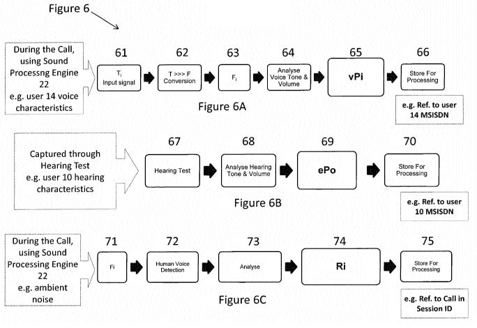
Figure 6 illustrates the processes involved in acquiring a user's hearing and
voice profile by
way of input conditioning for voice (figure 6A), output conditioning for
hearing (figure 6B) and
optional ambient conditioning (figure 6C). Any or all of the input, output and
ambient conditioning
can be enabled or disabled as required by the user. For example, if a user of
enhanced audio is holding
a telephone conversation and then passes their phone to a friend to continue a
conversation, the friend
may not require audio enhancement as they may not have impaired hearing.
With reference to Figure 6A (conditioning the incoming voice through sound
processing
engine 22 towards user 10 as a registered subscriber 15A with hearing loss),
upon commencement and
during the call in session, the incoming voice is sampled at step 61 from a
user's communications
device (14 in Figure 1), or from another input device associated with user
14's unique identifier, for
example an MSISDN number. The signal is converted from the time domain to the
frequency domain
CA 03029164 2018-12-21
WO 2018/007631
PCT/EP2017/067168
12
at step 62 to provide a frequency domain signal, Fi at step 63. At step 64,
voice type (for example
soprano, mezzo-soprano, contralto, counter tenor, tenor, baritone or bass) and
volume is analysed to
result in a voice profile at step 65 where the voice profile of the speaker's
voice (characterisation of the
actuator) is derived. This allows the optional automatic moving of the sound
of the originator of the
voice (user 14) by one or more frequency (tone) steps as an error function
towards the hearing profile
of the hearing characteristic of the user receiving or hearing the incoming
voice (user 10 in this
instance). This voice profile is stored in database 25 with an associated
voice originator user id unique
to the user in question at step 66. This results in the voice profile not
necessarily needing to be derived
again if the same user (14) uses the same line (MSISDN) in a future call.
Statistical variation of the
voice may also be captured. This could indicate that a particular line
(MSISDN) is used by multiple
people and therefore, for such a line, voice characterisation may need to be
performed every time a new
call is made as it is not sufficiently predictable which user (voice) will be
making the call.
With reference to Figure 6B (conditioning the signal a user will hear from the
sound
processing engine 22), an audio hearing test signal is provided at step 67 to
a user's communications
device, or to another output device associated with user interface 24 of
configuration management
module 25. At step 68, the hearing tone and volume is analysed to result in a
hearing profile at step 69
(characterisation of the sensor ¨ the user's ear). The hearing profile
comprises parameters for
balancing different frequencies on the sound wave that is presented to a
subscribing user. It is a pseudo
prescription of the hearing of the user. Any particular user will hear an
incoming sound most
efficiently and with most clarity if the incoming voice is matched to their
hearing profile.
This hearing profile is stored in database 25 with an associated user id
unique to the user in
question at step 70. The profile may be considered a combination of the user's
hearing loss in
association with and taking into account the measured transducer and system
noise impact involved in
the test to give a combined hearing threshold specific to that user at that
time tailored to the telecoms
network. The combined hearing threshold may be unique to that user. It may be
a digital 'voiceprint'
threshold that is bespoke to the user. The term "threshold" may be considered
a hearing threshold, in as
much as a level (e.g. volume and/or frequency) at which a user can
satisfactorily hear an audio signal,
This threshold may be below that threshold of hearing loss. This
representation of hearing threshold
contrasts with traditional measures such as audiogram given the difference in
how the hearing loss is
_ .
transcribed to work on, be modified and transferred over a communications
network.
Further details as to the hearing test performed at step 67 are as follows:
Based on perceived hearing loss of the user (none, mild, moderate, severe or
severe-to-
profound according to various institutional measures), an initial volume for
the hearing test is
determined. The initial value may be determined by the user, in some
embodiments. In some
embodiments, the gender and/or age of the user may be alternatively or
additionally taken into account
when setting the initial volume.
The hearing test commences:
CA 03029164 2018-12-21
WO 2018/007631
PCT/EP2017/067168
13
I. Start Hearing Test
a) Instructions to the user for the hearing test may be provided via user
interface 24.
b) The media gateway controller 21B places a call to the user's phone.
As would be understood, it is the underlying network for example a broadband
network that
provides the user interface 24 (e.g. web portal to a user or voice activated
interface), and a voice
communications network for example telephony or VoIP that provides voice to a
user handset or
device. These networks run on different clocks e.g. a browser or laptop
clock versus a
telecommunications network clock. Therefore, knowledge of the delay between a
user hearing a tone
on their device, and acknowledging the tone being heard on the web portal may
cause errors or
inaccuracies in the hearing test where time to react to an automated test,
which could be altered by
differing clock values between networks, can determine an erroneous true or
false outcome at a
particular hearing test frequency which may affect measured threshold levels
of a user's hearing
capability and hence adversely affect that user's biometric profile (see
later). Therefore, master clock
and timers for the client and server (media gateway controller) platforms are
synchronised.
One way to synchronise clocks across a server and user device is as follows.
The user (client)
device, at the time of requesting commencement of a hearing test, requests a
plurality of pings from the
server (for example five). One or more of the plurality of pings may comprise
a spread of frequencies
representing voice or white noise. This may contrast with standard hearing
tests which uses specific
single frequency tones. The server sends a ping packet with a data payload of
the current server time.
The ping packet is received by the client device and sent after a set time gap
(for example one second).
After a further set time gap (for example two seconds) a replica of the ping
packet is sent back. This
can be repeated several times such that the server receives a plurality of
ping packets, each relative to
the corresponding originating packet sent back form the client device. From
these packets, the server
can calculate the transmission travel time from user to server as well as the
drift in the clocks at the
client and the server. This helps avoid the previously mentioned erroneous
true or false test results.
Further, as volume of a test decreases (see below), the time delay in a
keypress for a missed
hearing test is important for a test outcome. Test results are fine tuned with
half steps (5dB as opposed
to 10dB). The time taken to test can be reduced by having accurate clock
syncing information so that
the number of half steps can be reduced.
c) Deactivate the Sound Enhancement function towards the user's phone
d) Stream reference speech to the user's phone and request user to adjust the
sound volume in the
handset for comfort in hearing the reference speech
e) Synchronise the timers & test for hearing threshold @ 500Hz
f) Synchronise the timers & test for hearing threshold @ 1000Hz
g) Synchronise the timers & test for hearing threshold @ 2000Hz
Ii) Synchronise the timers & test for hearing threshold @ 3000Hz
i) Synchronise the timers & test for hearing threshold @ 6000Hz
CA 03029164 2018-12-21
WO 2018/007631 PCT/EP2017/067168
14
j) Activate the Sound Enhancement function towards the user's phone
k) Synchronise the timers & stream reference speech to the user's phone and
via user interface to
request the user to adjust the volume index
2. Hearing test is complete
On completion of the above hearing test, parameters are captured as a hearing
profile
(biometric data) within database 25 of the configuration and management module
23. The parameters
may be dependent on one or more of user hearing loss, system noise and
transducer effects.
Typically, for the hearing test, the stimuli will be 1/3 octave wide bands of
noise centred at
500, 1000, 2000, 3000 and 6000 Hz or higher. Preferably, the duration of each
test is about 1000ms,
including 20ms ramps for increasing and decreasing volume of stimuli between
background noise and -
60dB as an example. The spectral slopes of the stimuli are preferably steep,
preferably 90 dB/oct or
more.
The 1/3 octave wide noise is, in effect, white noise comprising a mix of one
or more human
voices and is tested at frequency bands up to the capability of the
communication system being used.
White noise comprising human voices provides the benefit of a more real world
test that rellects how a
conversation is delivered to the user and enables a more accurate
characterisation of both actuator
parameters (vocal chords) and sensor parameters (user ear). The white noise
used for each test may
characterise alternative sounding pronunciation (differing alphabets) sent to
user for fine tuning of
hearing profile parameters.
The suggested order of testing is: 500, 1000, 2000, 3000, 6000 Hz or higher
for a wideband or
super-wideband voice codec or up to 3000 - 3400Hz for a narrowband codec.
Narrowband and
wideband codes being the typical codecs used in legacy telecoms systems. A
test can be tailored for
the underlying communication means such as the network capability for
transporting audio be it via a
narrower or wider band. Measurements at one centre frequency are preferably
completed before the
next centre frequency is selected.
More detailed procedure for each test frequency is given below as an example
implementation:
a) The sound is presented at the initial level estimated as above
b) If a response of "yes" is given within, for example, 2 seconds of the end
of the sound, this is taken
as a "hit" and the level of the next sound is reduced by 10dB. If there is no
response within 2
seconds after the end of the sound, this is scored as a "miss" and the level
of the next sound is
increased by 10dB.
c) The next test sound may be presented after a variable time interval, to
avoid the user responding
"yes" at an anticipated time. If the response to a previous sound is a hit,
the next sound is
presented after a delay preferably randomly selected from the range 0.5 to 2
seconds after the
"yes" response. If the response to a previous sound is a miss, the next sound
should be presented
CA 03029164 2018-12-21
WO 2018/007631 PCT/EP2017/067168
after a delay preferably randomly selected from the range, for example, 2.5 to
4 seconds after the
end of the previous sound.
d) Step (b) is repeated until at least one hit has occurred, followed by a
miss. After the miss, the
signal is presented with the level increased by 10dB.
5 a. If the response is a hit, the signal level is decreased in 5dB
steps until a miss occurs. The
lowest level at which a hit occurs is taken as the threshold level for that
frequency.
b. If the response is a miss, the level is increased in 5dB steps
until a hit occurs, and then
the level is decreased in 5dB steps until a miss occurs. The lowest level at
which a hit
occurs is taken as the threshold level for that frequency.
10 This
procedure is repeated for each test frequency in turn. However, if the initial
response to
the previous test sound is a miss (meaning that the starting level was too
low), the starting level for the
current centre frequency is set to the threshold level at the previous
frequency plus a predetermined
amount, for example plus 25 dB.
The hearing test may be repeated at a later time which allows the user to see
the long term
15 change
in their biometrics parameters and reduces the standard deviation in the
captured threshold
parameters.
The final result of the combined hearing threshold or 'digital voiceprint' may
then be visually
and/or otherwise presented as specific to that user. The result can be
interpreted including, for example,
listening to the test result, saving the test result, cancelling the test
result or redoing the test. The
hearing test results can then be listened to to compare the processed versus
the unprocessed voice. This
may or may not lead to the recorded hearing threshold also being fine-tuned
further, for example using
adaptation of compression ratios and/or frequency levels such that the digital
voiceprint or the original
combined hearing threshold more accurately reflects user preferences and
tonality which can and may
be adapted over time as hearing loss or needs change. This digital fine tuning
is possible once the
combined hearing threshold reflecting personal hearing loss or needs alongside
system noise and
transducer effect has been measured as above. In other words, a user may
interface with a screen to
record and map their hearing loss. That is the combination of system "noise"
plus transducer impact is
used to create a digital threshold. The visual output may be considered a
"graphic" representation of the
conjoined hearing threshold of hearing loss and device transducer effect.
With reference to Figure 6C (taking into account at least one of ambient
noise, signal to noise
ratio, echo, packet loss and other detrimental effects), at step 71, a
frequency domain signal, F1 which
may be the same signal as that of step 63, or may be a newly acquired signal
to cater for live
conditions, is processed by a standard human voice detection algorithm at step
72, and analysed at step
73 to result in an ambient noise profile at step 74 (characterising the
channel used for audio delivery).
This noise profile is stored in database 25 with an associated user id unique
to the user in question at
step 75. As an extension to ambient noise conditioning, an optional alarm or
other signal indicative of
an audio signal to noise ratio that makes cognitive information exchange
difficult may trigger certain
CA 03029164 2018-12-21
WO 2018/007631 PCT/EP2017/067168
16
recorded messages to be sent to the users on a call so that they are aware of
the ambient noise issue and
they can move to an environment where noise is less perceptible. The user may
accept or reject the
alarm and hence provide feedback such that future alarms occur at an
appropriate time when the
individual user would have find cognitive information exchange difficult.
Other functionality such as
the ability to record a conversation may be provided to aid a hearing impaired
user to review and verify
the conversation after the event. For example, calls can be recorded and
stored and in combination
with feedback from the user, knowledge derived to pre-define and anticipate
future situations in which
a particular voice experience occurred could and therefore could be overcome ¨
in effect the sound
processing engine 22 can learn how to recognise, avoid or compensate for such
potentially difficult
voice scenarios by way of artificial intelligence. Over time this knowledge
databank can be built up
and stored in database 25, shared and used to develop and enhance the audio
enhancement and
processing algorithms for more generic use in other situations - such as fine
tuning a hearing threshold
for a range of voice ambient situations that cater for the environment and /
or the network signal
strength at that time, whether over a fixed, mobile or wireless network for
example. Typically, the use
of Al to improve user experience is not used real-time in the telecoms / IP
network, therefore the
present disclosure can improve the voice experience for those with addressable
hearing loss needs.
Figure 7 illustrates processing steps undertaken by sound processing engine 22
when it is
enhancing audio. As will be shown, parameters derived in the profiling process
of figures 6A, 6B and
optional 6C are used to enhance audio to the needs of the receiving user (user
10 in the example of
figure 1).
At a first step, 80, an input audio signal from a user (14) to be sent to a
subscribing user (10) is
acquired, and decoded at step 81. The audio signal is transformed into the
frequency domain at step 82
to result in a frequency domain signal at step 83. At step 84, ambient noise
is evaluated in the same
manner as Figure 6C, and the noise is removed at step 85. Thereafter, voice
profile parameters as
stored in database 25 during step 66 of voice conditioning are applied (step
86) to produce an enhanced
voice output at step 87 (still in the frequency domain).
At step 88, hearing profile parameters as stored in database 25 for the
recipient (subscribing
user 10) during step 70 are applied to the enhanced voice output, and at step
89 an enhanced voice
output is provided (in the frequency domain). At step 90, the enhanced voice
output is transformed
into the time domain so that an enhanced time domain signal results at step
91. At step 92, the
enhanced voice output is normalised to avoid clipping so that a normalised
voice output is provided at
step 93. Finally, the output is encoded for the underlying transmission
protocol at step 94 and
enhanced audio (termed a voiceprint) tailored for the hearing of the
subscribing user recipient (10) is
provided at step 95.
By way of examples, figures 9 and 10 illustrate the waveforms produced by the
sound
processing engine (frequency domain) when providing enhanced audio.
CA 03029164 2018-12-21
WO 2018/007631 PCT/EP2017/067168
17
Firstly, turning to figure 8, frequency response of the audio enhancement may
be tailored by
any or all of the response curves shown. Frequency bands are represented in
the horizontal axis, and
the vertical axis show the thresholds (the limit of hearing of a user for that
frequency) as determined
during a hearing test as previously described. The scale on the threshold axis
represents a sound
pressure level indicative of the sound volume.
A "flat" response (no variation in the frequencies) is shown by 100. "Low" is
enhancing the
sounds at lower frequencies (101), "Mid" enhances the mid bands (102) and
"High" enhances the
higher bands (103).
Figure 9 illustrates the frequency spectrum of sample real time sound passing
through sound
simulator processing using wideband voice processing at 16kHz. Figure 10
illustrates the same using
narrowband voice at 8kHz. The narrowband and wideband frequencies shown are
for illustrative
purposes only. Many other bandwidths of input signal may be dealt with.
When undergoing real time enhancement of audio signals such as speech or
music, any or all
of the flat, low, mid and high filters can be applied at any time depending on
hearing and voice profile
parameters stored in database 25 for a particular user.
As well as the derivation of the voice profile and hearing profile for a
particular user as
described above, an input voice to be sent to a subscribing user, may
optionally, in real time, have its
input tone moved towards the voice type of the recipient of the audio as
previously described in
relation to steps 64 and 65. This is by way of an error function acting on the
audio signal and applied
in sound processing engine 22, for example across filter banks. The variation
in tone desired can be
stored alongside the user's other profile data for future use. The tone
variation may be carried out
automatically when a subscribing or non-subscribing user calls a subscribing
user from a known
MSISDN. The voice type from a particular MSISDN can be stored in database 25
such that if a
different user calls from the same MSISDN, the automatic tone variation can be
turned off by way of
artificial intelligence built into sound processing engine 22. An example
implementation may be to
observe the standard deviation of the parameters representing the voice
profile and compare this with a
learnt threshold. Where the standard deviation value exceeds the learnt
threshold, sound processing
engine 22 can automatically turn off tone variation as it will assume a
different person is likely to be
using this incoming line.
As well as a hearing profile and ambient profile in relation to an input to be
sent to a
subscribing user, the volume of voice to be received can be adjusted a number
of ways:
= Simply amplify the volume of the output at the last processing stage
(step 92)
= Amplify the digital range of the input signal after removal of ambient
noise (step 85). The
amplification may be based on an error function using a feedback parameter
evaluated over a
time period, for example, 20 processing time intervals in the current
conversation.
= The above feedback parameter may be stored in the user's profile
information in database 25
as a long term variable.
CA 03029164 2018-12-21
WO 2018/007631 PCT/EP2017/067168
18
= Over a longer period of time, for example many conversations, the initial
parameters as used
by sound processing engine 20 can be tailored based on real world experience
of
conversations between certain users, providing an optimised voiceprint for a
user.
= Further, parameters of a hearing profile can be altered over time to
account for degradation in
a user's hearing whether or not the user undertakes a subsequent hearing test
to update their
hearing profile. For example, a user's hearing threshold worsens with age. The
disclosed
method and system can measure threshold loss over time, and, via the
combination of user
feedback, interrogation and artificial intelligence, hearing loss data in
relation to that user's
use of the phone, their age, sex and frequency loss is used to create a
predictive, dynamic
hearing threshold that can automatically adapt to that user's age and sex by
virtue not just of
its predictive abilities but by comparing such data to the relevant peer
group. In essence, the
algorithms link in with the Al by allowing interpretation not just of the
user's hearing
characteristics but also of the network signalling strength for a particular
conversation (e.g.
packet loss in fixed network or RF signal strength in wireless networks) such
that it can
predict that if the signal is poor, the hearing threshold can be shifted to a
lower level to
enhance the audio processing to deliver a more pronounced (higher volume)
voice signal.
This measure of hearing threshold, its adaptation of such a threshold over
time (age of user)
and against signal strength is unique since it allows the adjustment of user
hearing profiles
both over time to cater for degradation in user hearing, and for the immediate
conversation to
hand.
A hearing test, and use of results of the hearing test in order to modify
audio signals to a user
will now be described in more detail with respect to Figure 12. It will be
understood that the methods
now described can be used in conjunction with the method described, for
example, with respect to
Figures 6A to 6C and Figure 7 (and indeed any other embodiments of the
description).
The method described with respect to Figure 12 relates to a hearing test
carried out between a
network entity, for example a server residing in a communication network, and
a user communicating
with the server via a user device. The communication network may be a
telecommunication network.
The user device may be a phone, such as a mobile phone; alternatively the user
device could be a
laptop, tablet etc. It will be understood that by carrying out the hearing
test over the network, and with
a user's device, then this gives a more accurate portrayal of how the user's
hearing is affected in real-
world conditions. It also takes into account aspects specific to a particular
user. For example, the
hearing test may take into account network effects such as interference or
noise, or aspects particular to
a user's particular network provider such as particular compression algorithms
they use. It may also
take in to account aspects related to a user's specific device, =for example
transducer effect of the
device's speakers. It may also take into account aspects of the user's other
hearing devices, such as
hearing aids and/or implants.
CA 03029164 2018-12-21
WO 2018/007631 PCT/EP2017/067168
19
As shown at SI, a hearing test is conducted for a user over a communication
link established
between a network entity (for example an entity or server comprised in audio
enhancement component
20) in a communications network and a user device of a user (e.g. user 14).
(The communication link
may be established between the network entity and the user device by the user
initiating contact with
the server, for example by the user phoning a contact number of a service
provider of the hearing test.
Alternatively, the service provider may call the user on their user device,
for example at a pre-arranged
time. However, the link is established, it will be understood that the hearing
test is conducted over a
link that is established between a network entity in a communications network
and in combination with
a user device of a user.
In some embodiments, the hearing test may use a platform. This may be the same
media
enhancement platform as is used during calls or similar to such a platform.
The hearing test may
alternatively or additionally use a web based testing portal. This may
initiate and/or receive automated
calls to and/or from the user's phone. This portal may guide the user through
the test process via one or
more on-screen prompts or instructions. This portal may do this by interacting
with the media
enhancement platform.
The hearing test may be carried out in an automated or semi-automated fashion.
For example,
the user may follow automated prompts from the server/service provider.
Alternatively, the user may
speak directly with a human operator of the service provider who conducts the
hearing test. The
prompts may be visual prompts and/or spoken prompts. The prompts may be
displayed on a user
device of the user. The prompts may be provided on the same user device which
is in communication
with the server for conducting the hearing test. Alternatively, the prompts
may be provided on a
separate user device. For example, the user may follow prompts displayed on a
laptop or tablet, in
conjunction with carrying out the hearing test via their user device which has
the communication link
with the server of the service provider.
As shown at S2, the hearing test comprises providing audio stimuli to the
user. The audio
stimuli are provided to the user device at a plurality of test frequencies.
According to some embodiments the audio stimuli comprises white noise. The
white noise
may be based on one or more human voices, which more accurately mimics the
type of sounds that a
user will typically hear on their user device, such as during a telephone
call. According to some
embodiments the audio stimuli comprises 1/3 octave wide bands of noise.
According to some embodiments the providing audio stimuli to the user at a
plurality of test
frequencies comprises providing audio stimuli at two or more of 500Hz; 1000Hz;
2000Hz; 3000Hz;
6000Hz. These values are by way of example only and different values may be
used, including
frequencies lower than 500Hz and higher than 6000Hz. For example, values
higher than 6000Hz may
be used for a wideband or super-wideband voice codec, or up to 3000 - 3400Hz
for a narrowband
codec. The white noise may be played at the test frequencies in a pre-defined
order e.g. 500Hz;
1000Hz; 2000Hz; 3000Hz; 6000Hz. The change of frequency may be conducted in a
step-wise fashion.
CA 03029164 2018-12-21
WO 2018/007631 PCT/EP2017/067168
At S3, responsiveness to the audio stimuli received from the user device is
monitored. This
may also comprise measuring responsiveness. The monitoring responsiveness
effectively checks
whether the user has heard the audio stimuli that has been played to them. The
monitoring may for
example include monitoring for feedback from the user, such as a key-press on
their user device (which
5 may be the user's phone or associated laptop, tablet etc.) or for a
speech response from the user.
Prior to playing audio stimuli to the user, information may be obtained from
the user
regarding their hearing ability. In some embodiments, this may be at least in
part, assumed and/or pre-
defined also by gender and/or age. This may include obtaining an indication of
hearing loss of the user.
This may include obtaining information such as whether the user's hearing loss
is none, mild,
10 moderate, severe or severe-to-profound according to various
institutional measures. The user may be
requested to provide this information. The indication of the user's hearing
loss can be used to
determine an initial volume of the hearing test. The volume of the audio
stimuli can then be adjusted
during the hearing test, in response to the monitoring of responsiveness. For
example, in response to a
positive response from the user the volume may be decreased for the next
stimuli. This may occur in
15 5dB steps. Of course, the step change may be by other amounts in
different embodiments. In response
to a null response from the user, the method may comprise increasing the
volume of the audio stimuli.
The increasing the volume may comprise increasing the volume in 10dB steps. Of
course, the step
change may be by other amounts in different embodiments. In some embodiments
the adjustment of
volume of audio stimuli may occur at each test frequency.
20 According to some embodiments the duration of each audio stimuli is
1000ms or about
1000ms. Of course, this is by way of non-restrictive example and in other
embodiments the duration of
the audio stimuli could take other values. There may be a change or a
variation of volume within each
audio stimuli. For example, each audio stimuli may include one or more ramps
of
increasing/decreasing volume between a background noise level and 60dB (or
about 60dB). Again, this
value of 60dB is by way of example only and in other embodiments different
values may be used.
Based on the hearing test, and as shown at S4, a hearing profile may be
generated for the user.
This may be considered a hearing profile threshold. The hearing profile
comprises an accurate measure
of the user's hearing loss, taking in to account network effects such as
signal quality, network noise etc.
as well as effects pertaining to the user's device e.g. transducer effect.
Once the hearing profile is generated it can be stored in a memory of the
network entity. This
may be the same network entity which had the communication link with the user
device of the user and
which conducted the hearing test. Alternatively, it may be a different network
entity or on a device.
This is shown at SS. The hearing profile may additionally be stored at other
entities, including other
network entities or at the user device. In storing the hearing profile an
association may be made
between the user and/or user device. For example, the association may be
stored in a look-up table.
This enables that user's hearing profile to be obtained and used when
transmitting and modifying audio
signals to the user device of that user. In other words, the stored hearing
profile is available for
CA 03029164 2018-12-21
WO 2018/007631 PCT/EP2017/067168
21
modifying of audio signals to the user device. Of course, the network entity
may store a plurality
(which may be hundreds, thousands, millions etc.) of such associations between
users and/or user
devices and associated hearing profiles. According to some embodiments the
information associated
with the user comprises an identifier of the user. The identifier may be a
unique identifier. The
identifier may be for example a name of the user. The identifier may
additionally or alternatively
comprise an identifier of the user device of the user. For example, the
identifier may comprise an
MSISDN of the user device.
In some embodiments, the hearing test may comprise processing and fine tuning
of the output
of the hearing test. This may take place whilst the network entity is in
communication with the user, or
could take place after the user has completed listening to the audio stimuli.
This may enable fine tuning
of the hearing profile to the user's natural ear, and/or to fine tune the
hearing profile to a further
hearing device of the user (e.g. hearing aid or cochlear implant). In this
regard the method may
comprise visually displaying results of the hearing test to the user and/or an
operator in communication
with the network entity. The fine tuning may be carried out by the user, for
example via their user
device or a separate laptop, tablet etc. Additionally, or alternatively the
line tuning may be carried out
by an operator who is in communication with the network. For example, the
operator may be an
employee of the service provider of the audio modification service.
Figure 13 is a flow chart showing a method according to an example, viewed
from the
perspective of a user device.
At S 1 a user, via their user device, participates in a hearing test on a
communication link
established with a network entity.
At S2, the device receives audio stimuli at a plurality of test frequencies
over the
communication link. That is the hearing test is carried out in a manner as
described in detail above.
At S3, the user provides one or more responses to the audio stimuli to the
network entity. The
responses may be provided via the user device on which the user is listening
to the audio stimuli, or the
responses may be provided via a separate device of the user e.g. a laptop or
tablet of the user.
Subsequently the user can receive, at their user device, modified audio
signals as shown at
step S4. These modified audio signals are modified based on the hearing
profile that is created for the
user following the hearing test, as described in detail above.
The modified audio signals can be delivered to the user device of the user in
real time (and
ultimately to the user's natural ear, hearing aid or implant etc.). Say for
example a user who has carried
out a hearing test and has a stored hearing profile is user A. User A's
identifier (e.g. MSISDN) is stored
in association with the hearing profile of User A in the network. When a
second user, User B, calls
User A then, User A's hearing profile is retrieved from memory and the call
can continue with User
Ws voice (and indeed any other audio signals), being modified in accordance
with User A's hearing
profile (or "voiceprint"). The modifying of an audio signal may comprise any
one or more of: filtering
the audio signal; adjusting the amplitude of the audio signal; adjusting the
frequency of the audio
CA 03029164 2018-12-21
WO 2018/007631 PCT/EP2017/067168
22
signal; adjusting the pitch and/or tone of the audio signal. According to some
embodiments the audio
signal modification may be carried out by a sound processing engine in the or
a network entity.
According to some embodiments, ambient noise at a location of the user device
may be
recorded. The ambient noise may be recorded using one or more microphones of
the user device. The
ambient noise information can be transmitted to the network where it may be
stored. The ambient noise
information may be collected and stored in real time during a phone call, for
example. The ambient
noise information can then also be used in delivering modified audio signals
in real time to the user
device.
Some further details of audio signal modification will now be described, by
way of example.
Overview of an FFT-based signal processing function
Digital audio is usually regarded as consisting of a time series of audio
samples. In order to
preserve the illusion of a continuous sound, a new sample has to be converted
to analogue every time
period, this period being the reciprocal of the sampling frequency. However,
the actual processing of
the audio in this algorithm is not necessarily on a continuous sample-by-
sample basis, but by "frames"
of audio samples, which are 128 samples in length. Each frame, both reading
and writing may be
overlapped with the previous frame by 50 %. So each sample in the audio stream
may actually he sent
for processing twice.
The processing rate of the frames may be much slower than the audio sample
rate:
Fsl-F1 =Fs/(framelength/2)
where FsFFT is the sampling rate of the frame, Fs is the sampling rate in Hz
(of the audio samples) and
framelength is the number of samples in the frame. The sampling rate of the
processing may always be
one value, for example 16 kHz, but that if the audio stream arrives at any
other rate a sample rate
conversion may be required between the two rates.
In embodiments, an FFT (Fast Fourier Transform) length of 128 samples at 16
kHz may be
used. However, due to the context in which this algorithm is required, it may
be necessary to adapt the
number of audio samples which are inserted into each FFT frame.
With the two different sample rates running simultaneously, there may need to
be two
processes running in parallel to keep the processing continuous.
(1) An interrupt-driven process that takes the sample from the input stream
and puts it in an input
buffer, along with taking a sample from an output buffer to place in the
output stream.
(2) Frame based processing, which may be accomplished before the current
input/output sample
buffers overfill or empty, respectively.
The minimum audio time delay between input and output of this form of "overlap-
add"
processing is, in an example, 1.5 times the frame length. The buffer pointers
for the interrupt-driven
process may be updated within one sample period (1/Fs) once the full/empty
flag occurs, otherwise
stuttering of the audio may occur. If the frame processing is sufficiently
powerful, the frame may be
processed before the input/output buffers have run out or filled up.
CA 03029164 2018-12-21
WO 2018/007631 PCT/EP2017/067168
23
In the following pseudocode example of the processing, the major function of a
step is
indicated by a Roman numeral in bold (0, I, II, III, IV, V, VI) and each sub-
step of the processing is
numbered in normal type, eg (1). If there is conditional processing in a step,
the conditions are
indicated by numbers after the decimal point eg (1.1, 1.2, ....).
(0) Start: assuming that there has been accumulated either:
(0.0) 32 samples of audio at a sampling rate of 8 kHz or
(0.1) 64 samples of audio at a sampling rate of 16 kHz
in a buffer called input(i), i = 0....31 or 0...63, depending on sample rate.
Then the process continues as follows
(I) All audio samples need to be converted into a linear representation in
single precision (4-byte)
floating point format samples, hence any instantaneous compression needs to be
undone.
(1.1) if samples arrive in "mu-law" or
(1.2) "A-law"coding,
(1.3) any other non-linear coding format
These can be undone with the inverse function (using a look-up table).
Pseudocode : xt_lin = inv_law(input);
where xt_lin are the sample values in linear format, and input is the incoming
latest buffer. inv_law() is
the mapping function between compressed sample value (8 bit integer, hence 256-
entry table
sufficient) and the floating point representation of the linear sample value.
In embodiments, this is done one buffer at a time, to prevent repeated
function calls for every sample.
(II) Data is expected to arrive at one of two sampling rates, either 8 kHz,
(standard telephone
rate) or 16 kHz (wide bandwidth). Hence, in embodiments, all processing is
performed at a 16
kHz sampling rate in fixed length "frames".
(1) Sample-rate conversion may be performed within the FFT structure.
Each FFT frame is half filled with the most recent input buffer, the remaining
half is filled from the
previous input buffer. Thus, there may be a 50% overlap of samples between
adjacent frames (each
input buffer appears in two consecutive frames). There may also be "zero-
padding" outside of the
inserted audio samples.
(2) Construct an empty frame of length 128 samples once to hold the linear-
coded audio samples.
(index 0 to 127)
Pseudocode: x= zeros(128,1);
(3.1) If the audio is at 8 IcHz sampling rate, after the arrival of the latest
32 audio samples, then these
samples can be inserted into input(0 ......................................
31) at index positions 65 , 67, 69 127 in x. For the very first
frame in a new processing sequence, the rest of the array may be left unfilled
(filled with zero's). For
all other frames, index positions 1, 3, 5 ....................... 63 may be
filled with the 32 samples from the previous
input buffer (0 .. 31).
CA 03029164 2018-12-21
WO 2018/007631 PCT/EP2017/067168
24
(3.2) If the audio is at 16 kHz sampling rate, the latest 64 audio samples may
be inserted into
input(0 .... 63) and place them at index positions 64, 65, 66, .......... 127
in the frame. For the first frame in a
new processing sequence, the rest of the frame may be left unfilled (0....63).
For all other frames, index
positions 0, 1, 2, 3, .. 63 may be filled with the 64 samples of the previous
input buffer.
(4) Generate a "window" function. This may be a symmetric ramp in shape and a
0-pi representation of
a sine wave. This can be pre-calculated into a small array, and may be used
again in the processing.
The sample values of this window at index i are called W(i).
Pseudocode: for = 0, 1,2 .. 127
W(i) = sin ((i+0.5)*(pi/N))
where pi = 3.14159265 and N is the audio array size (N=128).
(5) The frame array is "windowed". This is a sample by sample multiplication
between the audio
stream and the window W(i).
Pseudocode: xw(i) = W(i) * x(i); for i = 0 127
(III) Perform a forward FFT on this data frame.
(6) Pseudocode: xf = fwd_fft(xw);
The FFT function will generate a same-length array, but the data type will
change to comprising
complex numbers.
(a) The output array is considered as two halves, positive frequency and
negative frequency. For each
point in the output array, its equivalent frequency can be calculated as:
f(i) = i*Fs/N for i ¨ 0,1, 63(2)
f(i) = (1284)*Fs/N for i = 64, 65, ...... 127 (3)
where Fs is the sampling rate (16 kHz), and i is the index into the 128-point
array (assuming that the
function has returned the full array. N is the array size (N=128). Equation
(2) defines the "positive
frequency" side of the FFT array while equation (3) defines the "negative
frequency" side of the array.
Ri=o) is 0 Hz, and therefore a real number, representing the average level (DC
level).
Using Fs = 16,000 and N = 128, then the "bin spacing" or (f(i+1)-f(i)) = 125
Hz.
(b) Some libraries may include an FFT function explicitly designed for audio,
more specifically for
real-only data. They will produce a half-sized array comprising just the
values for the positive
frequency. Internally, such library functions will perform the necessary
manipulations on the negative
frequency components to produce the correct forward and inverse transforms,
thereby saving
processing power.
(c) If the returned array from the FFT has both positive and negative
frequency components, any
calculation performed on a frequency point in the positive frequency domain
does not have to be
repeated in the negative frequency domain, just the complex conjugate of the
equivalent positive
frequency point needs to be copied across.
CA 03029164 2018-12-21
WO 2018/007631 PCT/EP2017/067168
(6.1) If the input audio stream was originally sampled at 8 kHz, then the
components in the FFT array
where f(i) > 4000 (Fs/2) will need to be set to zero (potentially both halves
of the array).This is to
remove "aliasing"; performing a sample rate conversion from 8 kHz to 16 kHz.
Pseudocode: i_stop_pos = round(4000*Fs/N);
5 i_stop_neg = round (128¨ (4000*Fs/N) );
xf( i> i_stop_pos & i <63) = 0;
xf( i < i_stop_neg & i > 63) = 0;
The rounding function is used to ensure that no fractional indices are
generated, and guards against
future changes in sample rate or N.
10 (6.2) If the input audio stream was originally sampled at 16 kHz, then
no processing is necessary.
(IV). The core of the code: software to implement insertion gain and
compression during the
FFT. (Effectively a loop back function if no processing inserted here)
The compression system here is designed to operate in the frequency domain,
but splitting the audio
signal into 4 channels, calculate the short-term channel power and on the
basis of this, apply a
15 dynamically varying gain that maps the audio signal back into audibility
and comfort for the, for
example, hearing-impaired user.
Software for one-off pre-calculations necessary for each user
Every user will have different hearing characteristics, thus for every user a
unique hearing aid setting
may be calculated:
20 (A) Insertion gain (IG) for "65" dB SPL speech, IG65, as a function of
FFT frequency
The precise value of gain as a function of frequency is calculated via the
audiogram measure.
Pseudocode: [freq_ig, gain_dB] = IG65(audiogram, age, hearing aid experience);
Whereby, freq_ig may be on a logarithmic scale, and gain_dB will express the
gain in decibels, a
logarithmic function of linear gain.
25 Pseudocode: gain_dB = 20 log10(gain_linear);
gain_linear = 10^(0.05 * gain_dB);
This gain may be applied in the frequency domain to the FFT of the audio
frame. Therefore, the gain
values are interpolated from the [freq_ig, gain_dBI grid to the linear
frequency grid of the FFT.
This is done with two different methods: a first method is to interpolate the
linear gain on a linear
frequency scale, or a second method of interpolating the logarithmic gain (dB)
on a logarithmic
frequency scale.
Given:
f(i) i*Fs/N for i = 0,1, 63 (2)
and f(i) = (128-i)*Fs/N .......... for i = 64, 65, 127 (3)
(assuming 2-sided FFT calculation)
then
Pseudocode:
CA 03029164 2018-12-21
WO 2018/007631 PCT/EP2017/067168
26
If (f(i) <min(freq_ig))
Glinf(i) = gain_lin(min(freq_ig));
Glogf(i) = gain_dB(min(freq_ig));
elseif (f(i) > max(freq_ig))
Glinf(i) = gain_lin(max(freq_ig));
Glogf(i) = gain_dB (max(freq_ig));
else
scale
Glinf = lin_interp(freq_ig, gain_lin, f);
Glogf = lin_interp(log10(freq_ig), gain_dB, log10(f));
end
In the first 'if' loop it may be determined whether the handle gains are for
frequencies below
the lowest of the IG65 array. If the condition is met then the logarithmic
gain may be interpolated
against a logarithmic frequency using minimum frequency values.
The second `elseir loop will determined whether the handle gains are for
frequencies above
those of the IG65 array. If the condition is met then the logarithmic gain may
be interpolated against a
logarithmic frequency using maximum frequency values.
If neither of the conditions are met then the values may be linearly
interpolated.
Where values of gain are required at frequencies outside of the original
insertion gain array
then there is no extrapolation, but the same gain value is extended from the
relevant end of the insertion
gain array.
Care may be taken that the log 1 0(f) or log10(freq_ig) does not get violated
if f=0 or f < 0, as
this could cause errors.
Pseudocode for linear interpolation:
NewY(i) = OldY(f(j)) + (01dY(f(j+1) ¨ OldY(f(j))) * (NewX(i) ¨ OldX(j)) /
(01dX(j+1) ¨
OldX(j));
where OldX(j) and OldXf(j+1) are X points within the known (x,y) function,
which bound the value
NewX(i), where NewY(i) is desired to he calculated.
(B) Calculate the channel levels for a speech-shaped noise after application
of IG65.
This forms part of a calibration procedure. There are two principle stages of
gain applied to
the 141-1 array. (i) the prescribed insertion gain (for 65 dB SPL speech) and
(ii) the dynamic
compression gain. The user-specific insertion gain may be applied before the
dynamic range
compression software. For a speech input of 65 dB SPL, the combinations of
gains need to be the same
as the prescribed insertion gain. A correction factor may be calculated so
that the dynamic compression
gain is 0 dB when the channel power for the compressor is that generated when
a 65-dB SPL speech
noise is applied. Hence the channel levels are calculated under such a
circumstance. Although this can
be done in the PET domain, in preferred embodiments it is completed with a
signal file with the same
CA 03029164 2018-12-21
WO 2018/007631
PCT/EP2017/067168
27
digital RMS as the level at which the insertion gains are specified. MAS can
supply a 2-sec noise file
with the desired spectrum, but which may be scaled before use, depending on
defined reference levels.
Channel edge frequencies may be calculated for the compression system. This
allows the audio signals
to be split into 3 or 4 separate channels in the FFT processing in order to
manipulate them semi-
independently. Since the calculations are completed in the FFT domain, the
bandpass filtering has
already been performed, but on a fixed, linear frequency grid. To calculate
channel powers, the power
from the individual FFT bins that lie within the band-pass section of our
desired channels may be
summed. Although the power is summed in the FFT bins, the "edge frequencies"
of the channels are
half-way between "bins" of the FF1, at n*125 + 125/2 Hz, where n is an
integer.
(a) POTS, where speech occupies 300-3400 Hz, and transition bands at the edge
of the signal are
allowed for.
Frequency span FFT bin numbers (called ChanjFFTbin{ Start/End })
Channel (1) 250 to 750 Hz 2 ¨ 6
Channel (2) 750 to 1500 Hz 7 ¨ 12 (NB do not double-count bin at 750
Hz)
Channel (3) 1500 to 3500 Hz 13 ¨28 (NB do not double-count bin at 1500 Hz)
Channel (4) 3500¨ 3875 Hz 29¨ 126 (Dummy channel, should not be
carrying signal)
(11) wide-bandwidth speech:
Frequency span FFT bin numbers (called ChanjFFTbin{ Start/End })
Channel (I) 0 (DC) to 750 Hz 0 ¨ 6
Channel (2) 750 to 1500 Hz 7 ¨ 12
Channel (3) 1500 to 3500 Hz 13 ¨ 28
Channel (4) 3500 to 7875 Hz 29¨ 126
So process the noise calibration signal in the FFT domain and form the average
level of the channel
powers.
Pseudocode
(i) The array is initialised (only needed at the very start).
for j = I, 2, 3 ; ChannelPower65(j) = 0; end
(ii) Apply insertion gain to xf:
xf_ig(i) = xf(i) * Glin(i);
(iii) Calculate the power in each FFT "bin"
BinPower(i) = xf ig(i) .*conj(xf ig(i);
(iv) Sum the powers from each bin into its relevant compression channel. Start
and end bins are given
above, in variables ChanjW1binStart to ChanjFFTbinEnd
for j= 1, 2,3, 4
Channe1Power65(j) = sum( BinPower(i) );
The T value will span several bins.
CA 03029164 2018-12-21
WO 2018/007631 PCT/EP2017/067168
28
The vector `ChannelPower65' is calculated for each frame generated in
processing the calibration
signal (indexed by k).
Then: CalibPower65(j) = mean (ChannelPower65(j, k));
Finally convert this power to dB:
CalibLeve165dB(j) = 10*logIO(CalibPower65(j) ); for j = 0....3;
Note that this 10*log10() contains an implicit sqrt(), to convert from
CalibPower to CalibMagnitude.
Although insertion gains and CR are selected for each individual user, other
parameters may not, and
are defined so as to give good audio quality.
These are:
(a) Channel compression thresholds, Chan_dBthr, which are expressed as a
decibel number relative to
the channel level when carrying 65 dB speech-shaped noise, ChanOdBGn_lvl.
Chan_dBthr ranges from
0 to -15.
(b) Attack and release times for the channel compressors: att and rel,
expressed in milliseconds, the
speed with which the compressor responds to changes in input level. Attack
times (when the signal
level is rising) are usually much less than the release times (when the signal
is falling in level), but at
least a 2:1 ratio.
(c) The relative level at which a channel compression limiter cuts in above
the output of the channel
compressor, deltaFSdB, expressed in deciBels, typical values 10¨ 20.
(d) Attack and release times for the channel limiters: t_att_lim and
t_rel_lim. These are typically set to
3 and 80 msec respectively.
(C) At the very start of the processing, the following calculations may be
completed for each
channel (assume that each variable may be calculated on a per channel basis)
(C.1) Expon = (1 -CR)/CR
[CR] may never be below 1.
(C.2) The compression threshold, expressed in dB, is converted to a linear
value
c thresh = 10A(.05*Chan_dBthr)
(C.3) A channel calibration factor is calculated. This is referenced to the
channel level when carrying
65 dB speech, hence why this was calculated in sect B above.
GOdB_norm = (10"(-.05*CalibLeve165dB))^Expon
(C.4) Constants are calculated to implement the attack and release times of
the system used to calculate
the short-term mean level, I. These times are defined as the time for the gain
signal to settle to within 3
dB of final value (attacking), or 4 dB of final value (releasing) when a 35 dB
step change in level has
been applied at the input to the compressor (the numbers 35, 3 & 4 will appear
below). For very low
values of CR, typically around < 1.2, the full gain change is barely above 3
or 4 dB, meanings errors
can occur in calculations. Therefore error checking is implemented, requiring
the compressor to
implement at least this gain change. Calculations of the short-term mean
level, I, are updated every
CA 03029164 2018-12-21
WO 2018/007631 PCT/EP2017/067168
29
frame, using a calculated sampling rate, which depends on the FFT size, degree
of overlap and sample-
based sampling rate.
_______________ = Fs/(14.F1 size/Overlap) = 16000/(128/2) = 250;
Frames per seconds are calculated. The overlap between FFTframes is 50%, hence
"/2" figure.
Calculate:
(i) min_dstpdB = 35/8;
To ensure that no problems at low CRs. Here the value used is to divide by 8
to get greater than 4 dB
change, effective when CR<=1.14
(ii) dstp_att = max(min_dstpdB, 35 ¨ 3*CR/(CR ¨ 1));
Select maximum gain change value.
(iii) dstp_rel = max(min_dstpdB, 35 ¨ 4*CR/(CR ¨ 1));
Select maximum gain change value.
(iv) k_att = 10^(0.05*(-dstp_att/(t_att*FsFFT/1000)));
Lan is converted to milliseconds
(v) k_rel = 10^(0.05*(-dstp_rel/(t_rel*FsFFT/ I 000)));
(C.5) Constants may be calculated to implement the attack and release times of
the compression limiter
guarding each channel from overload.
(i) CRlim = 100;
Very high CR so as to get true limiter
(ii) dstp_att = max(min_dstpdB, 35 ¨ 3*CRlim/(CRlim ¨ 1));
dstp_rel = max(min_dstpdB, 35 ¨ 4*CRlim/(CRlim ¨ 1));
(iii) k_att = 10^(0.05*(-dstp_att/(t_att_lim*FsFFT/1000)));
k_rel = 10^(0.05*(-dstp_rel/(t_rel_lim*FsFFT/1000)));
(iv) ExponLim = (1 - CRlim )/CRlim;
(v) deltaFSlin = 10^(-0.05*de1taFSdB);
The difference ratio between channel compressor action and limiter action.
(C.6) Initialise "state" vectors that will carry the most recent versions of
the channel mean levels.
for j = 1, 2, 3, 4
ChanMeans(j) = Cthresh(j);
ChanLimMeans = Cthresh(j);
End
(D) Frame-based processing
For every 141-'1 frame an array is expected (xf) of frequency-domain samples.
Apart from the FFT array
to process, and the pre-calculated constants (insertion gains, compressor
settings, calibration constants),
a "state" vector of the running means of the channel compressors may be passed
in and the channel
limiters.
Pseudocode
CA 03029164 2018-12-21
WO 2018/007631 PCT/EP2017/067168
function [xfproc, ChanMeans, ChanLimMeans] = implement_hearing_aid(xf,
ChanMeans,
ChanLimMeans );
Which comprises the following steps:
(D.1) Implement linear insertion gains
5 xf_ig(i) = xf(i) Glin(i)
(D.2) Calculate compressor channel powers in a similar method used for
calculating channel levels in
calibration:
(i) for j = 1, 2, 3 ; ChannelPower65(j) = 0;
Initialise array. This is only needed at very start.
10 (ii) Apply insertion gain to xf:
xf_ig(i) = xf(i) * Glin(i);
(iii) Calculate the power in each FFT "bin"
BinPower(i) = xf ig(i) .*conj(xf_ig(i);
(iv) Sum the powers from each bin into its relevant compression channel. Start
and end bins are given
15 above, in variables ChanjFFTbinStart to ChanjFFTbinEnd
for j = 1, 2, 3, 4
ChannelPower(j) = sum( BinPower(i) ); (NB T spans several bins)
ChannelLevel(j) = sqrt( ChannelPower(j) );
end
20 In the calculation look the sqrt() function is computationally heavy.
(D.3) 4 gains may be calculated, one for each compression channel. Therefore,
a running average is
generated. If the new signal level is higher than the previously measured mean
level, then the signal is
deemed to be "attacking". If the signal is deemed 'attacking', the faster
attack time constants are used.
If the new signal level is less than or equal to the previously measured mean
level, then the signal is
25 deemed to be "releasing". If the signal is deemed 'releasing', the
slower release time constants are
used. The max() function is used to stop the NewChanMeans dropping below the
compression
threshold. If this is not implemented, then after a long period of silence, if
a high level is experienced,
the compressor may take a long time to come out of a very low mean level.
(i) Generate new mean values for both a channel compressor and its limiter
30 for j = 1, 2, 3, 4
Calculate new ChannelMean for compressor
if ChannelLevel(j) > ChanMeans(j)
k = k_att;
else
k = k_rel;
end
NewChanMeans(j) = max(cthresh(j), (1-k).* ChannelLevel(j) + k.*ChanMeans);
CA 03029164 2018-12-21
WO 2018/007631
PCT/EP2017/067168
31
The limiter value is calculated in a similar way to the mean calculation, its
mean value tracks relative to
the compressor levels
LimiterLevel(j) = ChanLevelardeltaFSlin(j);
if LimiterLevel(j) > ChanLimMeans(j)
k = k_attlim; To% in 1-1,1 implementation this may be unity.
else
k =
end
NewLimMeans(j) = max(cthresh(j), (1-k).* LimiterLevel(j) +
k.*ChanLimMeans(j));
end
(ii) Calculate compressor gain from new mean level, but also, in some
embodiments, add in an extra
gain reduction based on the ratio of the limiter mean to the compressor mean.
The computational
complexity of (a) a divide and (b) two exponentiations, may be removed using
look up tables to
eliminate exponentiations.
Gain(j) = (NewChanMeans(j) A Expon(j) ) * GOdB_norm(j);
if NewChanMeans(j) < NewLimMeans(j) // Limiter will cut in.
Gain(j) = Gain(j) * (NewLimMeans(j)/NewChanMeans(j)) A ExponLim(j));
end
(iii) Expand the 4 channel gains up to the FFT arrray size. Each gain is
assigned to the bin index from
which the corresponding channel power was calculated. Indexes were stored in
variables
ChanjFFTbinStart to ChanjFFTbinEnd
Initialise array once, at the start of processing.
GainFFT = zeros(1,NFFT);
Then in every frame (and account for negative frequencies in filling FFT
array, if necessary):
for j = 1, 2, 3, 4
GainFFT(ChanjFFTbinStart(j) ....... ChanjFF1 binEndChannelPower(j) =
Gain(j);
End
(iv) This leaves GainFFT as an array with rectangular steps at the channel
edges. This could cause
errors when the values are transformed back into the time domain. Therefore
the edge values are
smoothed with a 3-tap FIR filter, whose coefficients are Tap3 = [0.28 0.44
0.28], which is indexed by
k. The filter is "run" forwards & backwards across the entire half of the
(frequency domain) array,
taking care to ensure that the filtering does not "shift" the Gain function
relative to its starting points.
Since it is a symmetric FIR filter, forwards and backwards are the same,
meaning the same code can be
applied for the second pass, but with a different starting array.
(iv. I) Pass 1 : Remove potential overlap/indexing problems at the ends of the
arrays.
for i = {0,63}
SmootheGainl(i) = Gain (i);
CA 03029164 2018-12-21
WO 2018/007631
PCT/EP2017/067168
32
end
Perform an FIR filter on the edge values
for i = 2 ........ 62
SmootheGainl(i) = Gain(i-1)*Tap3(1) + Gain(i)*Tap3(2) + Gain(i+1)*Tap3(3);
end
(iv.2) Pass 2 : Remove the potential overlap/indexing problems at the ends of
the arrays.
for i = {0, 63}
SmootheGain2(i) = SmootheGainl (i);
end
Perform an FIR filter on the edge values
for i = 2 ........ 62
SmootheGain2(i) = SmootheGain1(i-1)*Tap3(1) + SmootheGainl(i)*Tap3(2) +
SmootheGainl(i+1)*Tap3(3);
end
(iv.3) Expand SmootheGain2 array back out to negative frequencies, if
necessary.
(iv.5) Apply compressor gain to array which has already had the insertion gain
applied.
for i = 0 ........ 63
xf proc(i) = xf_ig * SmootheGain2(i);
end
(iv.5) Update and save variables holding these mean levels
ChanMeans = NewChanMeans; //4 channels
ChanLimMeans = NewLimMeans; //4 channels
(iv.6) return xf_proc from function, along with updated means (or keep them
safe until next frame)
(V) Perform an inverse FFT on this data frame.
(i) Pseudocode: xproc = inv_flt(xf);
Unless using an audio-specific inverse FFT function, the output of this
function should be real. If the
output is returned as an array of complex numbers, then a check may be
performed during development
to ensure that the imaginary parts are zero.
Once the checks have been performed, discard the imaginary part and keep the
real part. Additionally,
if the forward and backward fft() functions are reciprocal, there should be no
change in scaling of the
audio.
(ii) Perform the same point-by-point multiplication, as in the windowing
function described in section
(5) above.
Pseudocode: for i ¨ 0 .. 127
xwproc(i) = W(i) * xproc(i);
(VI) Perform insertion of new frame of data into output audio stream
CA 03029164 2018-12-21
WO 2018/007631 PCT/EP2017/067168
33
The earliest 64 samples of xwproc (0 63) are overlapped with the last 64
samples of the previous
frame of xwproc and added together and indexed as the next available time
buffer to be sent to the
output stream (prepared for once the output stream has finished playing out
the last output buffer).
This is called an "overlap-add" procedure. The latter 64 samples from xwproc
are saved for the arrival
of the next version of xwproc.
(i) Pseudocode output16(i) = xwproc(i) + xwproc'(i+64); for i = 0 63
xwproc = xwproc; II save for next iteration of algorithm.
where xwproc' is the previously calculated frame.
"output16" is therefore a 64-long array of audio samples, at the 16 kHz
sampling rate.
(ii) In embodiments, if the original audio sampling rate was 8 kHz, an output
buffer is created
consisting of the odd-numbered elements of output 1 6. No low-pass filtering
is necessary since there
should be no alias components due to the low-pass filter performed at stage
III(6.1).
Pseudocode: output8 = output16(1, 3,5, 63);
In embodiments, if the original audio sampling rate was 16 kHz, the output
buffer is the same
as output16.
So overall, the frame-based processing takes an input buffer (size of 32
samples at 8 kHz or
64 samples at 16 kHz) and produces one output buffer (size of 32 samples at 8
kHz or 64 samples at 16
kHz), thus maintaining a constant flow of audio between input and output.
The double-windowing function, with the overlap-add, produces unity
recombination where
the inverse-fft output arrays overlap. If a "buzz" at the framerate appears in
the output audio then a
possible error has occurred.
According to some embodiments the user of the user device, or a network
operator, can
selectively activate or deactivate a setting which provides the audio signal
modification. This may be
useful, for example, if a user does not require the audio modification for
some reason. This may also be
useful where the user device of the user is also used by other people who may
not require the audio
modification.
A further aspect is shown in Figure 14, which shows a user device 1400. The
user device 1400
may be a mobile phone, for example, or indeed any other kind of digital
device. The user device 1400
comprises a display 1402. The user device 1400 also comprises a plurality of
microphones, as
represented by the black circles 1404. In this example the device comprises
twelve microphones. It will
be understood that in other examples more or fewer microphones may be
provided. Such a user device
may operate in conjunction with the earlier described embodiments. The array
of microphones 1404
can receive noise, and transmit information of that noise, to the network to
be processed as previously
described. The microphones 1404 may be directionally focused. The microphones
may be linked to an
operating system of the user device 1400. In turn, the operating system may be
communicatively linked
to the hearing profile of the user, which enables audio signal adjustment
unique to that person. By way
of example the user device 1400 may be placed at the front of a desk or on a
support, and picks up
CA 03029164 2018-12-21
WO 2018/007631 PCT/EP2017/067168
34
audio signals (e.g. voice or music). Those audio signals can then be
transmitted by the user device 1400
to the network, where they may be processed for tailoring audio signals to the
user of the user device,
in conjunction with the hearing profile for that user.
The user device 1400 further comprises a coating or layer 1406. The coating
1406 may be in
the form of a metal band or a coil. The coating 1406 may act as an antenna
and/or an induction loop
and/or a T-coil (tele-coil), or indeed any other assistive device or accessory
to communicate from the
user device 1400 to a hearing aid of a user. The coating 1406 may further
comprise a battery and/or
processor and/or memory, so as to increase battery life and/or processing
power and/or storage
capability of the user device 1400. This can also help the T-coil or other
applications needed to connect
to hearing aids. The coating 1406 may also have tagging and/or internet of
things (IoT) capability
incorporated therein. Such capability may specify a user's unique Hearing
Identification Code. In some
embodiments the coating 1406 is in the form of a casing which is attachable
and detachable from the
user device 1400.
Accordingly, improved audio enhancement is provided tailored for the hearing
requirements
of a particular user in a real time manner based on and specific to pre-
measured and configured hearing
loss and needs of the individual.
The described methods may be implemented by a computer program. The computer
program
which may be in the form of a web application or 'app' comprises computer-
executable instructions or
code arranged to instruct or cause a computer or processor to perform one or
more functions of the
described methods. The computer program may be provided to an apparatus, such
as a computer, on a
computer readable medium or computer program product. The computer readable
medium or
computer program product may comprise non-transitory media such as as
semiconductor or solid state
memory, magnetic tape, a removable computer memory stick or diskette, a random
access memory
(RAM), a read-only memory (ROM), a rigid magnetic disc, and an optical disk,
such as a CD-ROM,
CD-R/W, DVD or Blu-ray. The computer readable medium or computer program
product may
comprise a transmission signal or medium for data transmission, for example
for downloading the
computer program over the Internet.
An apparatus or device such as a computer may be configured to perform one or
more
functions of the described methods. The apparatus or device may comprise a
mobile phone, tablet,
laptop or other processing device. The apparatus or device may take the form
of a data processing
system. The data processing system may be a distributed system. For example,
the data processing
system may be distributed across a network or through dedicated local
connections.
The apparatus or device typically comprises at least one memory for storing
the computer-
executable instructions and at least one processor for performing the computer-
executable instructions.
Fig. 11 shows the architecture of an example apparatus or device 104. The
apparatus or
device 104 comprises a processor 110, a memory 115, and a display 135. These
are connected to a
central bus structure, the display 135 being connected via a display adaptor
130. The example
CA 03029164 2018-12-21
WO 2018/007631
PCT/EP2017/067168
apparatus or device 100 also comprises an input device 125 (such as a mouse,
audio input device
and/or keyboard), an output device 145 (for example an audio output device
such as a speaker or
headphone socket) and a communications adaptor 105 for connecting the
apparatus or device to other
apparatuses, devices or networks. The input device 125, output device 145 and
communications
5 adaptor 105 are also connected to the central bus structure, the input
device 125 being connected via an
input device adaptor 120, and the output device 145 being connected via an
output device adaptor 140.
In operation the processor 110 can execute computer-executable instructions
stored in the
memory 115 and the results of the processing can be displayed to a user on the
display 135. User
inputs for controlling the operation of the computer may be received via input
device(s) 125.