Note: Descriptions are shown in the official language in which they were submitted.
CA 03029166 2018-12-21
WO 2018/019868 PCT/EP2017/068846
- 1 -
Method and Apparatus for Manufacturing a Liquid-Filled Capsule
The present invention relates to a method and an apparatus for manufacturing a
liquid-filled breakable capsule for use in a smoking article, such as a
cigarette or
the like, as well as to a liquid-filled breakable capsule itself.
Smoking articles, such as cigarettes or the like, are popular consumer
products
that typically have a generally cylindrical rod shaped configuration and
include a
charge, roll, or column of a smokable material, such as shredded tobacco (e.g.
in
cut filler form), surrounded by a paper wrapper forming a so-called "tobacco
rod".
A cigarette will also usually have a cylindrical filter element aligned in end-
to-end
relationship with the tobacco rod. The filter element may, for example,
comprise
cellulose acetate tow, and the tow is circumscribed by a paper material known
as
"plug wrap". Typically, the filter element is attached to one end of the
tobacco rod
using a circumscribing wrapping material known as "tipping paper".
In recent years there has been increasing consumer demand for smoking articles
providing modified sensory attributes, and particularly for cigarettes
incorporating
filter elements which may act as vehicles for adding flavour to mainstream
smoke
of the cigarettes. Specifically, these smoking articles have included flavour-
altering
substances in breakable pellets or capsules. During cigarette manufacture, the
filter material is formed into a continuous filter rod having such pellets or
capsules
positioned within that rod; e.g., along a longitudinal axis thereof. The
continuous
filter rod is then divided or cut at predetermined intervals to form a
plurality of filter
elements, such that each filter element includes at least one of the capsules.
The
capsules are then manually broken by the consumer to release a substance into
the filter material which, in turn, may act to alter the flavour or taste of
the main-
stream smoke during smoking.
CA 03029166 2018-12-21
WO 2018/019868 PCT/EP2017/068846
- 2 -
For this purpose, a breakable capsule having a shell or casing containing a
liquid
is used. The shell or casing defines a cavity for receiving and holding the
liquid
and includes an open end, which is typically sealed or covered with a cap. The
casing or shell may include a predefined rupture region such that, when the
s consumer applies pressure to the capsule, the casing or shell breaks
preferentially
in the rupture region. In this manner, it is possible to control release of
the liquid to
ensure that it is directed to a desired area.
Japanese unexamined patent application published as JP H 05-330503 discloses
a manufacturing process for mass-producing such liquid-filled breakable
capsules.
As shown in Figure 4 of that Japanese patent application (included as Fig. 1
of the
present application), a tray feed zone B supplies a tray 3 upon which a
plurality of
capsule shells 2 are arranged and positioned under a sheet 1 fed or supplied
from
a sheet feed zone A. A heat seal apparatus C hot welds the sheet 1 to each of
the
shells 2 on the tray 3 and a cross-feed device D cuts the sheet 1 welded to
each of
the shells 2 to form a square cover on each shell 2. Top-cover wrap equipment
E
then bends an edge region of the cover to an outer peripheral surface of the
shell.
A discharge device G discharges the tray 3 with the finished capsules and a
sheet
winding portion F winds up remaining sheet 1 from which the covers were cut.
It has been found that the known techniques for manufacturing such liquid-
filled
capsules produce an excessive number of capsules which do not meet the desired
operating or use requirements; for example, with respect to the amount of
liquid
contained within the capsule and/or the sealing efficacy. It is therefore an
object of
the invention to provide an improved method and apparatus for manufacturing a
liquid-filled capsule for use in a smoking article. In particular, it is an
object of the
invention to increase a yield of the manufacturing process for this type of
capsule
with adequate capsule filling and/or sealing.
In accordance with this invention, a method and an apparatus for manufacturing
a
liquid-filled capsule for use in a smoking article is provided having the
features as
recited in claim 1 and claim 9, respectively. Furthermore, in accordance with
this
CA 03029166 2018-12-21
WO 2018/019868 PCT/EP2017/068846
- 3 -
invention, a liquid-filled capsule for use in a smoking article is provided
having the
features recited in claim 13. Advantageous or preferred features of the
invention
are recited in the dependent claims.
Thus, according to one aspect, the invention provides a method of
manufacturing
breakable capsules for use in smoking articles, comprising the steps:
providing a capsule shell defining a cavity and having an open end;
dispensing a volume of liquid into the cavity through the open end, whereby
a space or clearance is provided between an upper surface of the liquid
dispensed
into the cavity and the open end of the shell; and
sealing the open end of the shell with sheet material, such as polymer sheet
or film, to provide a breakable capsule containing the volume of liquid.
In this regard, the inventors have ascertained that the amount of liquid
within the
cavity has a significant impact or influence upon the production and
performance
characteristics of the capsule. For example, the ability to seal the open end
of the
shell can be compromised, especially when the speed of the production process
is
increased. On the one hand, if the filling ratio of the capsule is less than a
pre-
defined threshold value, the capsule will generally not contain sufficient
liquid and
a consumer may experience an unsatisfactory smoking experience. On the other
hand, if the space or clearance between the open end of the shell and the
liquid is
less than a predefined threshold value, the capsule may not seal properly and
may
leak in situ before the smoking article reaches a consumer.
It will be noted that the term "filling ratio" as used herein refers to a
ratio of volume
of liquid contained in the capsule to a filling capacity of the capsule
cavity. It will
also be noted that the term "filling capacity" as used herein refers to a
nominal
value of the volume of the cavity defined by the shell and not to a real value
of the
volume of the cavity that takes into account accepted manufacturing
tolerances.
In a preferred embodiment, the space or clearance is a linear dimension
measured
from an upper surface of the liquid dispensed into the cavity and the open end
of
CA 03029166 2018-12-21
WO 2018/019868 PCT/EP2017/068846
- 4 -
the capsule shell. That is, the clearance is typically measured between the
upper
surface of the liquid and a rim or an edge of the open end of the shell. In
this
regard, it will be appreciated that this measurement is typically performed
with the
capsule positioned in an upright orientation; that is, with the sealed open
end (i.e.
the filling end) of the capsule facing upwards. The space or clearance is
preferably
at least 0.4 mm, but is more preferably at least 0.6 mm, and further
preferably at
least 0.8 mm.
The clearance may be measured, for example, using a laser measuring device
that makes two relative distance measurements from a reference position. In
this
regard, a first relative distance corresponds to a distance between the sealed
end
(excluding a thickness of the sealing sheet or "cap") and the reference
position,
while a second relative distance corresponds to a distance between the upper
surface of the liquid and the reference position. The clearance is then
calculated
as the absolute value of the subtraction of the first and second relative
distances.
In a preferred embodiment, the liquid dispensed may comprise purified water or
a
water-based liquid which contains a dissolved or suspended flavouring
substance.
Such a liquid typically generates a negative meniscus and, thus, the upper
surface
of the liquid would be located at a position where the liquid in the cavity
contacts a
side wall of the shell.
In a preferred embodiment, the step of dispensing the volume of liquid into
the
shell comprises providing the capsule with a filling ratio above a
predetermined
minimum, and preferably within a pre-defined range. As noted above, the
filling
ratio of the capsule is a ratio of the volume of liquid dispensed to a filling
capacity
of the cavity. The predetermined minimum of the filling ratio is preferably
0.5. The
pre-defined range of the filling ratio is preferably from 0.5 to 0.9, more
preferably
from 0.75 to 0.9, and most preferably 0.8 to 0.9. A filling ratio of 0.88 has
been
found to provide exceptionally good production and performance characteristics
of
the capsule.
CA 03029166 2018-12-21
WO 2018/019868 PCT/EP2017/068846
- 5 -
In a preferred embodiment, the step of sealing the open end of the shell
includes:
covering the open end of the capsule shell with a section of the sheet
material;
fusing or bonding the section of sheet material to seal said end of the shell;
and
cutting excess sheet material from the section of sheet material at the sealed
end
of the shell, especially from a rim. Preferably, the step of sealing the open
end of
the shell comprises substantially contouring or shaping the end of the shell
during
cutting of the excess sheet material from the sealed end of the shell. The
cover or
closure formed by the sheet material over the end of the shell may be referred
to
as a cap. The sheet material is preferably cut with a rotary blade cutter due
to the
relatively small size of the capsules, which typically have a diameter in the
range
of between 2.5 mm and 8.0 mm. Alternatively, however, a laser or a punch may
be
used to cut the sheet material.
In a preferred embodiment, the method further comprises the steps of:
inspecting
the liquid-filled capsule or a component thereof (e.g. the capsule shell, the
cover,
or the liquid contained in the shell) for a manufacturing defect; and
identifying the
capsule as defective if a manufacturing defect is detected. Possible
manufacturing
defects may, for example, include a deviation or discrepancy in shell
dimensions,
a misalignment of the cover and shell, a deviation or discrepancy in the
capsule
dimensions, and/or liquid leakage. The term "manufacturing defect" used herein
is
understood as an unacceptable deviation or discrepancy from a target or
desired
manufacturing parameter, i.e. outside a predetermined tolerance band.
Preferably,
the method comprises the step of rejecting a capsule which has been identified
as
defective. In this way, a defective capsule can be ejected or removed from
further
processing in the production of the smoking articles. This, in turn, avoids
wasting
manufacturing effort on capsules which are unsatisfactory for use in the
smoking
article (e.g. which will not operate satisfactorily for a consumer in use) or
are likely
to break during production of the smoking article (i.e. creating waste and/or
soling
of equipment).
In a preferred embodiment, the method comprises the steps of: providing a
holding
device to hold the capsule shell; and conveying the holding device together
with
CA 03029166 2018-12-21
WO 2018/019868 PCT/EP2017/068846
- 6 -
the capsule shell during and/or between one or more of the steps of:
introducing a
liquid into the cavity, sealing the open end of the shell, inspecting the
capsule or a
component thereof, identifying the capsule as defective, and rejecting a
capsule
identified as defective. In a particularly preferred embodiment, the holding
device
is configured to hold a plurality of capsule shells. Thus, the holding device
may be
configured as a tray having a plurality of cells or receptacles, each of which
is
adapted or designed to hold a respective capsule shell, which is conveyed
along
or between two or more of the dispensing, sealing, inspecting, identifying and
rejecting steps.
As will be appreciated, the step of dispensing the liquid into the cavity
through the
open end of the capsule shell involves substantially filling the cavity of the
shell
with the liquid. In the event that a holding device configured to hold a
plurality of
capsule shells is employed, the step of dispensing the liquid or of filling
the cavity
may occur for the plurality capsule shells simultaneously. In this regard, a
liquid
dispensing device may be employed which is configured to dispense or inject
the
liquid into a plurality of shell cavities simultaneously.
In the event that a holding device configured to hold a plurality of capsule
shells is
employed, in a preferred embodiment the method includes the steps of:
positioning a plurality of capsule shells on the holding device;
referencing a position of each individual shell relative to the holding
device;
and
conveying the holding device with a position reference conveyor system
between at least two steps selected from the steps of: introducing or
dispensing a
liquid into the cavity, sealing the open end of the shell, inspecting the
capsule or a
component thereof, identifying the capsule as defective, and rejecting a
capsule
identified as defective.
By referencing the position of each individual shell relative to the holding
device
and conveying the holding device with a position reference conveyor system,
the
relative position of each individual shell can be known and tracked along a
path of
CA 03029166 2018-12-21
WO 2018/019868 PCT/EP2017/068846
- 7 -
the manufacturing process. As a result, when a defective capsule is identified
and/or rejected, it is possible to trace the origin of the capsule, thereby
reducing
maintenance time.
In the event that a holding device configured to hold a plurality of capsule
shells is
employed in the method of this invention, the step of sealing the open end of
the
shell may include: covering the open end of each a plurality of capsule shells
with
the sheet material; fusing or bonding the sheet material to seal said end of
each of
the plurality of shells; and cutting excess sheet material from the sheet
material at
the sealed end of each shell. As noted above, the step of sealing the open end
of
the shells may comprise substantially contouring or shaping the ends of the
shells,
which may occur during cutting of the excess sheet material from the sealed
ends
of the shells.
According to another aspect, the present invention provides an apparatus for
manufacturing a liquid-filled capsule for use in a smoking article,
comprising:
a holder for holding one or more capsule shells;
a conveyor for moving or transporting the holder with the one or more
capsule shells;
a filling station for dispensing a liquid into a cavity of each of the capsule
shells held by the holder, wherein the filling station is configured to
provide a pre-
defined space or clearance between the liquid dispensed into the cavity and
the
open end of each shell; and
a sealing station for covering and sealing an open end of each capsule shell
with a sheet material to form a capsule.
As noted above, in a preferred embodiment the pre-defined space or clearance
is
at least 0.4 mm, more preferably at least 0.6 mm, particularly preferably at
least
0.8 mm.
In a preferred embodiment, the holder for holding the one or more capsule
shells
comprises a tray having a plurality of cells, each of which is configured to
receive
CA 03029166 2018-12-21
WO 2018/019868 PCT/EP2017/068846
- 8 -
and hold a respective capsule shell. The conveyor for moving or transporting
the
holder may comprise one or more of a conveyor arm, a conveyor belt, and a
turntable. The filling station preferably comprises one or more nozzles in
fluid
connection with a supply reservoir of the liquid. Each nozzle is configured to
dispense a predetermined volume of the liquid into a respective one of the
shells
via an open end of each shell.
In a preferred embodiment, the sealing station comprises a supply roll of the
sheet
material, a heat-sealing device for fusing the sheet material to a rim at the
open
end of each capsule, and/or a cutting device for cutting excess sheet material
from
the rim at the end of each capsule. The sheet material is preferably drawn
from the
supply roll by a feed roller. The cutting device is preferably configured to
cut the
excess sheet material and to contour or shape the rim at the end of each
capsule.
In a preferred embodiment, the apparatus further comprises a discharge
conveyor
for discharging the capsules from an inspecting station to a delivery station.
The
discharge conveyor is preferably configured as a vacuum conveyor that suctions
or draws (via suction) the capsules from the holder.
In a preferred embodiment, the apparatus further comprises a rejecting station
at
which a defective capsule is removed.
According to a further aspect, the present invention provides a liquid-filled
capsule
for use in a smoking article, the capsule comprising: a capsule shell defining
a
cavity and having an end with a filling opening; a volume of liquid contained
within
the cavity; and a cap which covers and seals the filling opening. The capsule
has a
pre-defined space or clearance provided between an upper surface of the liquid
contained in the cavity and the end of the shell.
In a preferred embodiment, a maximum diameter of the capsule is in the range
from 2.5 mm to 8.0 mm, preferably from 3.0 mm to 7.5 mm, more preferably from
CA 03029166 2018-12-21
WO 2018/019868 PCT/EP2017/068846
-9-
35 mm to 7.0 mm. In this regard, a maximum capsule diameter at the lower end
of
the range is naturally preferred for fat slim cigarettes and super slim
cigarettes.
In a preferred embodiment, a height of the capsule is in the range from 3 mm
to 17
mm, preferably from 6 mm to 14 mm, further preferably from 8 mm to 12 mm, and
particularly preferably from 9 mm to 11 mm.
In a preferred embodiment, the pre-defined space or clearance is at least 0.4
mm,
preferably at least 0.6 mm, more preferably at least 0.8 mm; e.g. about 1.0
mm.
In a preferred embodiment, a filling ratio of the capsule is above a
predetermined
minimum, and preferably within a pre-defined range. The predetermined minimum
of the filling ratio is 0.5, and the pre-defined range of the filling ratio is
from 0.5 to
0.9, preferably from 0.75 to 0.9, and more preferably 0.8 to 0.9. In this
regard, the
filling capacity of the cavity may be in the range of 50 I to 300p.1,
preferably in the
range of 751.1.1 to 2504 and optionally in the range of 1000 to 2004
For a more complete understanding of the invention and the advantages thereof,
exemplary embodiments of the invention are explained in more detail in the
following description with reference to the accompanying drawing figures, in
which
like reference characters designate like parts and in which:
Fig. 1
is a schematic illustration of a known manufacturing method and
apparatus from the prior art;
Fig. 2a
is a perspective side view of a capsule manufactured according to
one preferred embodiment of the invention;
Fig. 2b
is a perspective side view of a capsule manufactured according to
another preferred embodiment of the invention;
CA 03029166 2018-12-21
WO 2018/019868 PCT/EP2017/068846
- 10 -
Fig. 2c is a cross-sectional view of a capsule manufactured
according to a
further preferred embodiment of the invention;
Fig. 2d is a schematic side view of a capsule manufactured
according to a
preferred embodiment of the invention;
Fig. 3 shows a schematic example of a holding device used to
convey
shells in a manufacturing method and apparatus according to an
embodiment of the invention; and
Fig. 4 is a diagram schematically illustrating an apparatus for
performing
a method of manufacturing a capsule according to an embodiment
of the invention.
is The accompanying drawings are included to provide a further
understanding of the
present invention and are incorporated in and constitute a part of this
specification.
The drawings illustrate particular embodiments of the invention and together
with
the description serve to explain the principles of the invention. Other
embodiments
of the invention and many of the attendant advantages of the invention will be
readily appreciated as they become better understood with reference to the
following detailed description.
It will be appreciated that common and well understood elements that may be
useful or necessary in a commercially feasible embodiment are not necessarily
depicted in order to facilitate a more abstracted view of the embodiments. The
elements of the drawings are not necessarily illustrated to scale relative to
each
other. It will further be appreciated that certain actions and/or steps in an
embodiment of a method may be described or depicted in a particular order of
occurrences while those skilled in the art will understand that such
specificity with
respect to sequence is not actually required. It will also be understood that
the
terms and expressions used in the present specification have the ordinary
meaning as is accorded to such terms and expressions with respect to their
CA 03029166 2018-12-21
WO 2018/019868 PCT/EP2017/068846
- 1 1 -
corresponding respective areas of inquiry and study, except where specific
meanings have otherwise been set forth herein.
With reference now to Figs. 2a, 2b, 2c and 2d of the drawings, three
embodiments
of a liquid-filled breakable capsule 100 according to the invention are
illustrated. In
each case, the capsule 100 comprises an open-ended shell 101 which is closed
and sealed with a cap 102. The shell 101 has a side wall or lateral wall 103
that
extends from an end wall 104 to an open end 105 and thus surrounds or defines
a
cavity 106 in the shell 101. Preferably, the lateral wall 103 ends in a rim
107 at the
open end 105 to facilitate application of the cap 102. The lateral wall 103
may be
generally cylindrical (cf. Figs. 2a and 2c) or may be faceted (cf. Fig. 2b).
The side
or lateral wall 103 may taper or narrow from the open end 105 towards the end
wall 104.
The end wall 104 of each shell 101 may include one or more lines of weakness
or
one or more stress concentrator elements 108 to create a weakened region, in
which the shell 101 is configured to break preferentially upon application of
a
compressive force to its side wall or lateral wall 103. In other words, the
shell 101
includes a predefined rupture region such that, when the consumer compresses
the sides of the capsule 100, the shell 101 will break preferentially in the
rupture
region. The shell 101 is typically made from a resiliently deformable
material, such
as a polymer material. The cap 102 is typically formed and cut from a section
or an
expanse of sheet material, such as a laminated plastic sheet material. The
liquid L
in the capsule may comprise purified water or a water-based liquid which
contains
a dissolved or suspended flavouring substance. As shown schematically in Fig.
2d, a volume of liquid L dispensed into the cavity 106 through the open end
105 of
each shell 101 is selected to provide a pre-defined space or clearance 6
between
an upper surface of the liquid L and the end 105 of the shell 101. The pre-
defined
space or clearance 6 may, for example, be selected to be in the range of about
0.8
to about 2.0 mm, and preferably in the range of about 0.9 mm to about 1.5 mm.
CA 03029166 2018-12-21
WO 2018/019868 PCT/EP2017/068846
- 12 -
An example of a breakable capsule 100 that can be adequately manufactured with
the method of the invention comprises a shell 101 made of LOPE and a cap 102
made of a plastic laminate having a layer of PE and a layer of PET, where the
PE
layer is the layer that is in contact with the rim 107 of the shell 101 in the
finished
capsule 100. The thickness of such a laminate layer is typically about 0.05
mm;
i.e. 50 pm. The liquid dispensed into the capsule 100 comprises purified water
with
a flavouring substance.
The target height of the shell 101 is 10.0 mm and the target outer diameter of
the
shell 106 is 6.28 mm. Such a shell 101 has a filling capacity of 131p1. The
target
height of the capsule 100 is 10.0 mm, whereas the target outer diameter of the
shell 101 is 6.70mm. The target volume of retained liquid is 115p1 and the
target
weight of the capsule 100 (shell 101, cap 102, and water) is 195 mg. In this
case,
this exemplary capsule 100 has a clearance 6 of about 0.95 mm and a filling
ratio
.. of about 0.88.
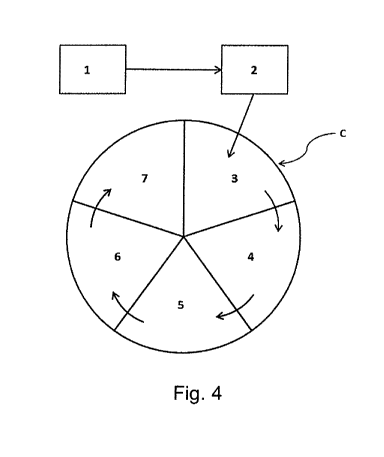
With reference now to Fig. 3 and Fig. 4 of the drawings, an embodiment of the
method and apparatus of the invention will be described. The shells 101 may be
moulded, preferably injection-moulded, in a moulding station 1 with a pair of
dies
(not shown) configured to produce a batch of shells 101. The shells 101 are
then
positioned on a tray 10 having a plurality of cells 11 configured to receive
and hold
the shells 101, preferably arranged in an array. The cells 11 are referenced
such
that their position within the tray 10 is known. As a result, each individual
shell 101
has a known position within the tray 10. The tray 10 may have capacity for
holding
one or more batches of multiple moulded shells 101.
Once the tray 10 is fully loaded with shells 101, a conveyor arm (not shown)
picks
up the tray 10 and conveys it to a shell inspection station 2. The conveyor
arm
moves or transports the tray 10 while maintaining the positioning reference of
the
.. individual shells 101. At the shell inspection station 2, the height and
diameter of
each shell 101 is measured, preferably optically measured by means of an
optical
measuring device, such as a camera. If the measured height and/or the measured
CA 03029166 2018-12-21
WO 2018/019868 PCT/EP2017/068846
- 13 -
diameter of any one of the shells 101 deviate(s) from a target value such that
it is
not within an established or predetermined tolerance band, that shell 101 is
then
identified as defective. This is an optional inspection step that can also be
omitted
without departing from the invention.
Thereafter, the conveyor arm again picks up the tray 10 holding the shells 101
and
conveys or transports it to a filling station 3 located on a turntable C. As
before, the
conveyor arm conveys the tray 10 while maintaining the positioning reference
of
the individual shells 101. The filling station 3 includes a liquid reservoir
connected
to a plurality of nozzles, which are configured and arranged to dispense the
liquid
into the cavities 106 of all the shells 101 on the tray substantially
simultaneously.
As an alternative, however, the filling station 3 could include a reduced
number of
nozzles configured and arranged to dispense to, and to fill, only a selection
of the
shells 101 at any given time. Each of the nozzles is adapted to dispense a
volume
of liquid to fill the respective shell cavity 106. In this connection, the
shells 101 are
desirably supported and held on the tray 10 such that the open ends 105 of the
shells 101 face upwards towards the nozzles, which fill the shells 101 from
above.
After the shell cavities 106 have been filled with the liquid at filling
station 3, the
turntable C is rotated (in the clockwise direction, as shown in Fig. 4) to
move the
tray 10 to a sealing station 4 where a sheet material is provided to cover and
seal
all of the open ends 105 of the shells 101. The sheet material is typically
supplied
or fed from a supply roll, preferably via a feed roller (not shown), such that
the
open ends 105 of all the shells 101 are covered simultaneously. Next, the
sheet
material is heat-sealed to the rim 107 of each shell 101.
The turntable C is then rotated further (in the clockwise direction, shown in
Fig. 4)
to move the tray 10 to a cutting station 5 where the sheet material sealed
over the
now covered ends 105 of the shells 101 is cut around each rim 107 to form an
individual cap 102 on each capsule 100. The cutting station 5 preferably
includes a
rotary blade cutter (not shown), which may be embodied as a roller having
blades
shaped to contour the shell rims 107. In this way, a batch of liquid-filled
breakable
CA 03029166 2018-12-21
WO 2018/019868 PCT/EP2017/068846
- 14 -
capsules 100 is obtained at this stage, with each capsule 100 containing a
volume
of dispensed liquid.
Further rotation of the turning table C (in the clockwise direction, shown in
Fig. 4)
causes the tray 10, now containing a batch of liquid-filled breakable capsules
100,
to rotate to a capsule inspection station 6. Here the height and diameter of
each
capsule 100 is measured or assessed. Additionally, any misalignment of the cap
102 to the shell 101 can be measured. It is also possible to inspect an aspect
of
the liquid L at the capsule inspection station 6, especially an opacity of the
liquid L.
These parameters are desirably measured optically, e.g. via an optical
measuring
device, such as a camera. If any of the measured parameters of a specific
capsule
100 is determined to deviate from a target value such that it is not within a
specific
predetermined tolerance band, that capsule 100 is identified as defective.
The turning table C is then rotated further (in the clockwise direction in
Fig. 4) to
move the tray 10 to a rejecting station 7 at which any defective capsules are
able
to be rejected and removed. In this regard, defective capsules 100 may
preferably
be ejected from the tray 10 by a jet of compressed air. The defective capsules
100
removed or ejected may be collected for disposal or recycling.
In an alternative embodiment, a vacuum discharge conveyor (not shown) may be
employed to remove a batch of the liquid-filled breakable capsules 100 from
the
tray 10 by applying a suction force and to convey them to a discharge area.
During
this transport of the capsules 100, any defective capsules may be ejected from
the
batch by discontinuing the suction force exerted on the defective capsules
100,
thus allowing them to drop from the conveyor at a rejection station.
Instead of employing a turn-table in this embodiment, it will be appreciated
that the
filling, sealing, cutting, inspection and rejecting stations could be provided
along a
belt-type conveyor without departing from the invention.
CA 03029166 2018-12-21
WO 2018/019868 PCT/EP2017/068846
- 15 -
Although specific embodiments of the invention have been illustrated and
described herein, it will be appreciated by those of ordinary skill in the art
that a
variety of alternate and/or equivalent implementations exist. It should be
appreciated that the exemplary embodiment or exemplary embodiments are only
examples, and are not intended to limit the scope, applicability, or
configuration in
any way. Rather, the foregoing summary and detailed description will provide
those skilled in the art with a convenient road map for implementing at least
one
exemplary embodiment, it being understood that various changes may be made in
the function and arrangement of elements described in an exemplary embodiment
without departing from the scope as set forth in the appended claims and their
legal equivalents. Generally, this application is intended to cover any
adaptations
or variations of the specific embodiments discussed herein.
In this document, the terms "comprise", "comprising", "include", "including",
"contain", "containing", "have", "having", and any variations thereof, are
intended
to be understood in an inclusive (i.e. non-exclusive) sense, such that the
process,
method, device, apparatus or system described herein is not limited to those
features or parts or elements or steps recited but may include other elements,
features, parts or steps not expressly listed or inherent to such process,
method,
article, or apparatus. Furthermore, the terms "a" and "an" used herein are
intended
to be understood as meaning one or more unless explicitly stated otherwise.
Moreover, the terms "first", "second", "third", etc. are used merely as
labels, and
are not intended to impose numerical requirements on or to establish a certain
ranking of importance of their objects.
CA 03029166 2018-12-21
WO 2018/019868
PCT/EP2017/068846
- 16 -
List of Reference Signs
1 moulding station
2 shell inspection station
3 filling station
4 sealing station
5 cutting station
6 capsule inspection station
7 rejecting station
10 tray
11 cell
100 capsule
101 shell
102 cap
103 side wall or lateral wail
104 end wall
105 open end
106 cavity
107 rim
108 line of weakness or stress concentrator
6 space or clearance
L liquid
C turntable