Note: Descriptions are shown in the official language in which they were submitted.
BODY CAVITY IRRIGATION INTEGRATED MANUAL CONTROLLER
AND PUMP DEVICE, SYSTEM AND METHOD
RELATED APPLICATIONS
[0001] This application claims the benefit of and priority of U.S.
Provisional
Patent Application Serial No. 62/359,897, filed July 8, 2016.
FIELD OF THE INVENTION
[0002] The present disclosure relates generally to body cavity
irrigation
devices, methods and systems and, in particular, to a body cavity irrigation
io integrated manual controller and pump device, system and method.
BACKGROUND
[0003] Transanal irrigation (TAI) is a process used by individuals who
have
bowel management issues, such as incontinence, constipation or other
neurogenic
bowel dysfunction (NBD). Alternatively, TAI may be used for regular bowel
is evacuations by individuals who are incapacitated due to illness or other
medical
conditions or injuries (such as spinal cord injury) and thus lack the mobility
to
access a toilet. During TAI, water or other lavage liquid is introduced into
the
rectum and colon through a device positioned through the anus so that feces
are
flushed and evacuated. This creates pseudo-continence for the patient/user.
20 .. Furthermore, individuals that are bedridden may develop fecal impaction.
Such
bowel obstructions may be removed via TAI.
[0004] Systems for performing TAI currently on the market allow the
user to
introduce water into the bowel through a rectal catheter while the user sits
on a
toilet or a commode/shower chair or lays in a bed. The user introduces an
amount
25 of water or other liquid into the bowel (typically 500-700 mL) in order
to flush out
stool located in the bowel passage. The user typically introduces the water,
waits
for a period of time and then allows gravity to flush the water and stool out
of the
body. The rectal catheter may have an inflatable/deflatable balloon to assist
in
retention of the catheter during water introduction. The balloon is typically
inflated
30 by a fluid such as air or water.
[0005] For TAI users, independence, dexterity, and ease of use are
important
needs that must be addressed by a TAI system or method.
[0006] A prior art TAI device is shown in U.S. Patent No. 8,579,850 to
Bjerregaard and uses water to inflate the balloon of a rectal catheter. This
system
1
Date Recue/Date Received 2022-02-24
CA 03030144 2019-01-07
WO 2018/009818 PCT/US2017/041127
has single-lumen tubing that provides water from a reservoir to a controller.
The
system features dual-lumen tubing from the controller to the catheter. One of
these
dual lumens enables the rectal catheter balloon to be inflated with water from
the
reservoir and later deflated; while the second lumen accommodates water
transfer
from the reservoir into the rectum. When the catheter balloon is deflated, a
liquid
communication channel is created so that water returning from the deflated
balloon
travels via the controller into the lumen towards the catheter, and thus into
the
rectum. As a result, the water from the deflated balloon does not return to
the
water reservoir. A disadvantage of such a system is that water from the
balloon is
unnecessarily directed into the patient.
[0007] Prior art systems that use controllers with built-in valves to
selectively
direct fluids to a flushing catheter and an inflation balloon are also known.
Examples of such systems are presented by the Bjerregaard '850 patent and U.S.
Patent No. 8,657,801 to Nielsen et al. Such controllers, however, use rotating
knobs to select the controller valve configuration, which can be difficult for
a
patient/user to manipulate. As a result, it is all too easy for a user/patient
to select
the wrong valve setting.
[0008] Furthermore, prior art manual pump TAI systems, such as the
systems
of the Bjerregaard '850 patent and the Nielsen et al. '801 patent, use a
squeeze
zo bulb to pump fluids. As a result, the user/patient must hold the squeeze
bulb in
addition to squeezing it to activate the pumping action. This can be awkward
for a
patient/user and may result in inadequate pumping pressure.
[0009] In addition, the catheters of the Bjerregaard '850 patent and the
Nielsen et al. '801 patent must be removed for flushed stool and lavage liquid
to
drain. This requires the catheter to be reinserted into the anus if multiple
flushing
cycles are to be repeated.
[00010] Accordingly is a desire to develop a TAI controller and pump
device,
system and/or method for bowel management that addresses at least some of the
above issues.
SUMMARY
[00011] There are several aspects of the present subject matter which may
be
embodied separately or together in the devices and systems described and
claimed
below. These aspects may be employed alone or in combination with other
2
CA 03030144 2019-01-07
WO 2018/009818 PCT/US2017/041127
aspects of the subject matter described herein, and the description of these
aspects together is not intended to preclude the use of these aspects
separately or
the claiming of such aspects separately or in different combinations as set
forth in
the claims appended hereto.
[00012] In one aspect, a system for performing irrigation of a body cavity
includes a reservoir configured to contain an irrigation liquid, a controller
and a
catheter configured to be at least partially inserted into the body cavity
having a
flushing passage, a drain passage and a retention balloon. A waste drain valve
is
in fluid communication with the drain passage of the catheter and movable
between
.. a closed configuration, where waste is retained within the drain passage,
and an
open configuration where waste flows through the drain passage. The controller
is
in fluid communication with the reservoir and the catheter and has a pump and
a
valve assembly. The valve assembly is changeable between configurations where,
when the pump is actuated: i) irrigation liquid is pumped from the reservoir
to the
retention balloon; ii) irrigation liquid is pumped from the reservoir to the
flushing
passage of the catheter; and iii) irrigation liquid is pumped from the
retention
balloon to the reservoir.
[00013] In another aspect, a method for irrigating a body cavity includes
providing a catheter having a waste drain valve, a flushing port and a
retention
zo balloon, a reservoir containing irrigation liquid and a controller
including a pump in
fluid communication with the reservoir and the catheter. A portion of the
catheter
including the retention balloon is inserted into the body cavity. The waste
drain
valve of the catheter is closed and irrigation liquid from the reservoir is
pumped to
the retention balloon using the controller so that the retention balloon is
inflated.
Irrigation liquid from the reservoir is then pumped to the flushing port of
the catheter
so that the irrigation liquid enters the body cavity. The waste drain valve of
the
catheter is opened so that liquefied waste is drained from the body cavity.
Liquid is
pumped from the retention balloon to the reservoir so that the retention
balloon is
deflated. The catheter is removed from the body cavity.
[00014] In yet another aspect, a device for irrigating a body cavity using
irrigation liquid from a reservoir and a catheter having a flushing port and a
retention balloon includes a pump and a valve assembly in fluid communication
with the pump. The valve assembly is changeable between configurations where,
3
CA 03030144 2019-01-07
WO 2018/009818 PCT/US2017/041127
when the pump is actuated: i) irrigation liquid is pumped from the reservoir
to the
retention balloon; ii) irrigation liquid is pumped from the reservoir to the
flushing
passage of the catheter; and iii) irrigation liquid is pumped from the
retention
balloon to the reservoir.
[00015] In yet another aspect, a device for controlling a flow of
irrigation liquid
between a catheter and a reservoir for use in flushing a body cavity of a user
includes a housing and a valve positioned in the housing and movable between a
first configuration and a second configuration. A gear train shaft is
rotatably
positioned within the housing and a valve gear is mounted on the gear train
shaft.
The valve gear engages the valve to move it between the first configuration
and the
second configuration when the gear train shaft is rotated. A ratchet wheel is
also
mounted on the gear train shaft and a toggle switch is slidably mounted on the
housing. A pawl is connected to the toggle switch and engages the ratchet
wheel
so as to turn the ratchet wheel and shaft when the toggle switch is slid.
BRIEF DESCRIPTION OF THE DRAWINGS
[00016] Fig. us a perspective view of an embodiment of the system of the
present invention;
[00017] Fig. 2 is an enlarged perspective view of the reservoir of Fig. 1
with the
fill cap removed, empty of liquid and ready for filling;
zo [00018] Fig. 3 shows the reservoir of Fig. 2 configured to be
filled with water;
[00019] Fig. 4 is an enlarged exploded perspective view of the housing,
pumping handle and the controller of Fig. 1;
[00020] Fig. 5 is an exploded view of the pumping bellows assembly of the
controller of Fig. 4;
[00021] Fig. 6 is an exploded view of the catheter waste drain valve switch
carriage assembly and one of the valves of the controller of Fig. 4;
[00022] Fig. 7 is an enlarged exploded view of the valve assembly and a
perspective view of the toggle mechanism of the controller of Figs. 1 and 4;
[00023] Fig. 8 is an enlarged bottom perspective view of the control
panel of
the toggle mechanism of Fig. 7;
[00024] Fig. 9 is a bottom plan view of the control panel of Fig. 8 with
the toggle
switch assembly added;
4
CA 03030144 2019-01-07
WO 2018/009818 PCT/US2017/041127
[00025] Fig. 10 is an exploded side elevational view of the toggle
mechanism of
Fig. 7;
[00026] Fig. 11 is an enlarged rear perspective view of the toggle
mechanism
of Figs. 7 and 10;
[00027] Fig. 12 is a front perspective view of the toggle mechanism of Fig.
11;
[00028] Fig. 13 is an enlarged perspective view of the bottom of the
handle
portion of the controller of Fig. 4 and a perspective view of a tubing and
drain valve
line connector prior to attachment to the controller;
[00029] Fig 14 is an exploded view of the tubing and drain valve line
connector
of Fig. 13;
[00030] Figs. 15A and 15B are enlarged perspective views of the tubing
and
drain valve line connector of Fig. 14 with the drain valve line slider in the
rest and
actuated positions, respectively;
[00031] Fig. 16 is a cross sectional view of a user's leg with the
controller of
Fig. 1 attached thereto;
[00032] Figs. 17A and 17B are perspective views of the catheter and hub
of
Fig. 1 in the connected and disconnected configurations, respectively;
[00033] Figs. 18A and 18B are exploded perspective views of the drain
valve
barrel member of the catheter of Figs. 17A and 17B with the barrel member in
the
zo closed and open positions, respectively;
[00034] Figs. 19A and 19B are exploded perspective views of the catheter
and
hub of Figs. 17A and 18B with the hub housing cover removed with the catheter
drain valve in the closed and open configurations, respectively;
[00035] Figs. 20A and 20B are schematic views of the drain valve of the
catheter of Figs. 17A-19B in the closed and open configurations, respectively;
[00036] Fig. 21 is an enlarged top plan view of the hub of Figs. 17B-18B;
[00037] Fig. 22 is an exploded view of the base latching mechanism of the
hub
of Figs. 17B-18B;
[00038] Fig. 23 is a perspective view of the housing of the catheter of
Figs.
17B-18B with the housing cover removed and the waste drain valve in the closed
configuration;
[00039] Fig. 24 is a cross sectional view of the catheter of Fig. 23
taken along
lines 24-24;
5
CA 03030144 2019-01-07
WO 2018/009818 PCT/US2017/041127
[00040] Fig. 25 is a cross sectional view of the catheter of Fig. 23
taken along
lines 25-25;
[00041] Fig. 26 is a schematic view of the system of Fig. 1;
[00042] Fig. 27 is a schematic view of the controller valve
configurations and
corresponding symbols of the indicator wheel of the toggle mechanism;
[00043] Figs. 28A-28E illustrate use of the controller to select valve
configurations;
[00044] Figs. 29A and 29B illustrate the controller slide switch for
controlling
the catheter drain valve in positions corresponding to a closed drain valve
and an
open drain valve, respectively.
DETAILED DESCRIPTION OF EMBODIMENTS
[00045] An embodiment of the transanal irrigation (TAI) system of the
invention
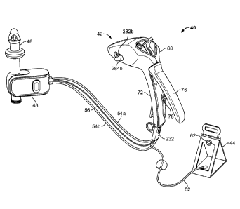
is indicated in general at 40 in Fig. 1. The system includes an integrated
pump
controller, indicated in general at 42, an irrigant or lavage liquid reservoir
44, a
rectal catheter 46 and a catheter hub 48. A single section of tubing 52 runs
between the reservoir and the controller. A pair of tubing sections 54a and
54b run
from the controller to the catheter base 48. In the embodiment of Fig. 1, the
lumens
of tubing sections 54a and 54b are never placed in communication with each
other
zo during a TAI procedure, i.e. there is no fluid communication between the
lumens.
As will be explained in greater detail below, this is accomplished since each
tubing
lumen is controlled independently by its own unique valve.
[00046] While the invention is described below in terms of use in a
transanal
irrigation procedure, it is to be understood that the invention could be used
to
irrigate other body cavities of a user including, but not limited to, stomas
and body
cavities accessible by stomas.
[00047] A sheath 56 containing a waste drain valve line also runs between
the
controller 42 and the catheter hub 48.
[00048] The rectal catheter 46 preferably is disposable and is attached
in a
removable fashion to (non-disposable) hub 48. The rectal catheter 46 may be
used
by a patient either on a toilet or the like or in a bed setting.
[00049] As illustrated in Fig. 2, the reservoir 44 houses a liquid tank
or
container 57 and features a fill opening 58 with a removable fill cap 62. As
6
CA 03030144 2019-01-07
WO 2018/009818 PCT/US2017/041127
illustrated in Fig. 3, with the fill cap removed, the container of the
reservoir may be
refilled with lavage liquid by a hose 64 that receives a liquid, such as
water, from a
water source 66.
[00050] With reference to Figs. 1 and 4, the controller 42 includes a
housing
that forms a head portion 68 and a handle portion 72. The housing is formed by
halves 74a and 74b. As will be explained in greater detail below, the head
portion
houses the controller valve assembly and associated toggle mechanism for
selecting the controller valve configuration, the pump bellows and the sliding
catheter drain valve switches. Controller connector ports are positioned on
the
bottom end of the handle portion, which also houses the internal tubing that
runs
between the valve assembly and connector ports as well as an internal control
line
for the catheter drain valve switches.
[00051] As shown in Figs. 1 and 4, a pumping lever 76 is pivotally
attached by
its proximal end (via opening 77 of Fig. 4) to the handle portion of the
controller (via
boss 79 of Fig. 4). A link 78 is pivotally attached by one end to the
underside of the
handle 76, while the opposite end of the link traverses grooves 82 (Fig. 4)
formed in
housing halves 74a and 74b as the handle 76 is actuated during pumping.
[00052] As shown in Figs. 4 and 5, a pumping bellows assembly is mounted
in
the head portion of the controller and includes a bellows 84 that contains an
interior
zo pumping chamber. The bellows is provided with ports 86a, 86b and 86c
that
communicate with the interior pumping chamber. The bellows 84 may be
constructed from rubber or any other liquid impermeable material that is at
least
semi-flexible.
[00053] The bellows 84 is mounted within a pumping bellows frame 86 that
features top and bottom plates 88 and 92 that are joined by their leading
edges by
a hinge arrangement. As an example only, the plates 88 and 92 may be
integrally
formed of plastic and joined by a living hinge. A spring tab 94 is formed on
upper
plate 88 and features a distal end that engages lower plate 92 so as to urge
the
plates into the positions shown in Fig. 5. The top and bottom surfaces of the
bellows 84 are attached to the plates 88 and 92, respectively, such as by
adhesive,
and thus the bellows is urged into the expanded configuration illustrated in
Fig. 5.
[00054] As illustrated in phantom at 96 in Fig. 5, a first end of a line
is attached
to plate 88 at line mounting bracket 98 and runs below pin 102 and over pin
104
7
CA 03030144 2019-01-07
WO 2018/009818 PCT/US2017/041127
that extend between the housing halves. The second end of the line is
connected
to the sliding end of link 78. While pins 102 and 104 are shown outside of the
controller housing for ease of illustration, pin 104 extends between boss 106
(Figs.
4 and 5) in housing half 74b and a corresponding boss formed in housing half
74a.
Pin 102 is similarly mounted between the controller housing halves, but in a
position within the head portion of the controller below the bellows assembly
and
generally in vertical alignment with the line mounting bracket 98.
[00055] In operation, when lever 76 is squeezed by the user towards the
handle portion of the controller housing (as illustrated by arrow 108 of Fig.
5), the
line 96 is pulled downward by the sliding end of link 78 so that the top plate
88 of
the bellows frame is moved towards the bottom plate (as illustrated by arrow
110)
against the urging of spring tab 94. This moves the bellows 84 into the
contracted
or compressed configuration so that liquid within it is pushed out of the
bellows.
When the lever 76 is released by the user, spring tab 94 moves the top plate
88 of
.. the bellows frame away from bottom plate 92 so that the bellows is moved
into the
expanded configuration (of Fig. 5). As a result, liquid is drawn into the
bellows.
The source of liquid drawn into the bellows and the destination of the liquid
pushed
out of the bellows is dictated by the setting of the controller valves, as
will be
described below.
zo [00056] As shown in Fig. 5, the bottom of the handle portion of
the controller is
provided with controller connector ports 112a, 112b and 112c. Port 112a is
connected to tubing 54a of Fig. 1, port 112b is connected to tubing 54b of
Fig. 1
and port 112c is connected to tubing 52 of Fig. 1. Internal tubing (not shown)
runs
between port 112a and the outlet of a fixed check valve 114.
[00057] As illustrated in Figs. 5-7, the controller features a valve
assembly that
includes three valve mechanisms: flushing valve 116a, balloon valve 116b and
reservoir valve 116c. As illustrated in Figs. 6 and 7, each of valve
mechanisms
116a-116c of the valve assembly is preferably a barrel valve that includes a
housing 118a, 118b and 118c within which is pivotally mounted a barrel member
120a, 120b and 120c, respectively. Valve housing 118a includes an inlet port
122a
and an outlet port 124a. Valve housing 118b similarly includes an inlet port
122b
and an outlet port 124b while valve housing 118c includes an inlet port 126
and an
outlet port 128. As illustrated in Figs. 5 and 6, the outlet ports 124a and
124b of
8
CA 03030144 2019-01-07
WO 2018/009818 PCT/US2017/041127
valve housings 118a and 118b and the inlet port 126 of valve housing 118c are
positioned within the openings 132a, 132b and 132c of a first valve mounting
plate
134. The inlet ports 122a and 122b of valve housings 118a and 118b and the
outlet port 128 of valve housing 118c are positioned within the openings 136a,
136b and 136c of a second valve mounting plate 138. Valve mounting plates 134
and 138 engage the housing halves 74a and 74b so as to secure the valve
mechanisms within the controller head portion.
[00058] With reference to Fig. 7, each barrel member 120a, 120b and 120c
includes a bore 142a, 142b and 142c as well as a gear portion 144a, 144b and
144c. Barrel members 120b and 120c are provided with ball members 146b and
146c positioned within the bores 142b and 142c, respectively. Each of the
bores
142b and 142c is provided with an opening on one end that features a chamfered
edge and is sized so that the ball members 146b and 146c will not exit. The
opposite end of each bore, through which the ball members 146b and 146c are
inserted into bores 142b and 142c, and which are visible in Fig. 7, receive
grills
148b and 148c in a fixed fashion (such as by adhesive or fasteners). As a
result, a
ball member is trapped within each bore and causes balloon valve 116b and
reservoir valve 116c to act as check valves in that liquid flow may only
travel in the
direction of arrows 152b and 152c. Barrel member 120a features a similar
zo construction (and thus is provided with grill 148a), but is not provided
with a ball
member so that it does not act as a check valve.
[00059] Internal tubing runs between the outlet port 124a of flushing
valve
mechanism 116a and the inlet to check valve 114 (Fig. 5). Internal tubing runs
between port 112b and the outlet port 124b of balloon valve mechanism 116b.
Internal tubing also runs between port 112c and inlet port 126 of reservoir
valve
mechanism 116c. The internal tubing described above is not shown for ease of
illustration.
[00060] The inlet port 122a of flushing valve mechanism 116a is received
within
bellows port 86a (of Fig. 5). The inlet port 122b of balloon valve mechanism
116b
is received within bellows port 86b. The outlet port 128 of reservoir valve
mechanism 116c is received within bellows port 86c.
[00061] The controller features a toggle mechanism, indicated in general
at 154
of Fig. 7, that includes a toggle switch 156 that may be moved from the rest
position
9
CA 03030144 2019-01-07
WO 2018/009818 PCT/US2017/041127
shown in Fig. 7 in the direction of arrows 158 to reconfigure the valves as
described
below. The toggle switch slides within an elongated trough 162 formed in a
control
panel 164. The bottom side of the trough is indicated at 166 in Figs. 8-10. As
illustrated in Figs. 8 and 10, the trough also features sidewalls having
elongated
openings 168. As shown in Fig. 10, a mounting stem 172 is secured to the
bottom
of the toggle switch 156 and is received within the elongated trough 162. A
pair of
sliding L-shaped spring retainers, illustrated at 174a and 174b of Figs. 9 and
10,
are secured to the stem 172 on opposite sides of the trough. More
specifically, pins
pass through the pair of openings 176 of stem 172, elongated openings 168 in
the
trough sidewalls, pair of openings 178 of spring retainer 174a and
corresponding
openings of spring retainer 174b.
[00062] As shown in Figs. 8 and 9, the bottom side of the control panel
features
tabs 182a and 182b to which are secured spring guide rods 184a and 184b,
respectively, in a fixed fashion. Spring retainers 174a and 174b each feature
an
opening (illustrated in phantom in Fig. 9 at 175a and 175b) that receives a
corresponding one of the spring guide rods 184a and 184b, respectively. These
spring retainer openings 175a and 175b are sized so that the spring retainers
slide
along the spring guide rods as the toggle switch is manipulated in the
direction of
arrows 158 (Fig. 7). Compression coil springs 186a and 186b (Fig. 9) are
zo concentrically positioned on spring guide rods 184a and 184b and are
engaged on
opposite ends by the tabs 182a and 182b and the spring retainers 174a and
174b.
As a result, toggle switch 156 is urged towards the central rest position
illustrated in
Fig. 7 and the compression coil springs 186a and 186b of Fig. 9 are
alternatively
compressed as the toggle switch is moved in either direction of arrows 158
(Fig. 7).
[00063] With reference to Fig. 10, a pair of pawls 192a and 192b having
proximal ends featuring openings 194a and 194b and distal ends having hook
portions 196a and 196b. As illustrated in Fig. 11, the proximal ends of pawls
192a
and 192b are pivotally mounted to and between spring retainers 174a and 174b.
More specifically, with reference to Fig. 10, a pin passes through the
openings
194a and 194b of the pawls 192a and 192b and corresponding openings of spring
retainers 174a and 174b (shown at 198 in Fig. 10 for spring retainer 174a).
[00064] Spring retainer 174b is absent from Figs. 10 and 12 for ease of
illustration.
CA 03030144 2019-01-07
WO 2018/009818 PCT/US2017/041127
[00065] A valve gear train, indicated in general at 200 in Figs. 11 and
12,
features a D-shaped shaft 202 upon which is mounted valve configuration gears
204a, 204b and 204c. In addition an indicator wheel lower gear 206 is mounted
on
the shaft. The ends of shaft 202 are pivotally mounted within the head portion
of
the housing of the controller.
[00066] A ratchet wheel (indicated in general at 207 in Fig. 10) is also
mounted
on the shaft 202 between valve configuration gears 204b and 204c and includes
a
first set of ratchet teeth 208a and a second set of ratchet teeth 208b. With
reference to Figs. 10-12, a first pair of springs 210a and 212a engage the
bottom
166 of the control panel trough and the top surface of the pawl 192a and
cooperate
to urge the hook portion 196a into engagement with the teeth 208a of the
ratchet
wheel. A second pair of springs 210b and 212b similarly cooperates to urge the
hook portion 196b of pawl 192b into engagement with the teeth 208b of the
ratchet
wheel. Spring 212b is missing from Fig. 12 for ease of illustration.
[00067] In operation, as the toggle switch 156 is moved in the direction of
arrows 158 of Fig. 7, the pawl hook portions 1 96a and 196b (Fig. 10)
alternatively
engage the teeth 208a and 208b of the ratchet wheel, respectively, so that the
shaft
202 (Figs. 11 and 12) of the valve train, and thus the valve gears of the
valve train,
are rotated either clockwise or counterclockwise (depending on the direction
of
zo movement of the toggle switch).
[00068] The gear portions 144a, 144b and 144c (Fig. 7) of the valve
mechanisms 116a, 116b and 116c are engaged and turned by the valve gears
204a, 204b and 204c (Figs. 11 and 12), respectively. As a result, the
configurations of the valve mechanisms are controlled by the movement of the
toggle switch 156, as will be described in greater detail below.
[00069] As shown in Figs. 11 and 1 2, an indicator wheel shaft 216 is
pivotally
mounted by end 218 within the head portion of the controller housing. An upper
indicator wheel gear 222 is secured to the shaft 216 in a fixed fashion, as is
an
indicator wheel 224 (not shown in Fig. 11 for ease of illustration). Upper
indicator
wheel gear 222 is engaged by lower indicator wheel gear 206 and thus is
turned,
as is shaft 216 and indicator wheel 224, when the gear train shaft 202 is
turned.
The indicator wheel is positioned below an indicator window 226 formed in
control
panel 164. The indicator wheel includes setting icons 228 that appear in the
11
CA 03030144 2019-01-07
WO 2018/009818 PCT/US2017/041127
indicator window based on the setting of the valve mechanism as directed by
the
manipulation of the toggle switch 156.
[00070] As illustrated in Fig. 1, the system tubing 52, 54a and 54b and
drain
valve control line sheath 56 are preferably connected to the controller by a
tubing
and drain valve line connector 232. The tubing and drain valve control line
connector is indicated in general at 232 in Figs. 13-15B. As noted previously,
the
bottom of the handle portion of the controller is provided with controller
connector
ports 112a, 112b and 112c. The connector 232 features four main components: a
cover 234, a main housing 236, a drain valve line sliding connector 238 and a
handle housing 242.
[00071] The housing 236 of the tubing and drain valve line connector 232
features a pair of cylindrical portions 243a and 243b that include bores 244a
and
244b. The open top ends of bores 244a and 244b receive the controller
connector
ports 112a and 112b in a liquid sealing but removable fashion. The open bottom
ends of bores 244a and 244b are connected to the ends of tubing 54a and 54b
(Fig. 1). Handle housing 242 includes a handle portion 243, that may be easily
engaged by a user's finger, and a bore 244c having an open top end which
receives controller connector port 112c in a liquid sealing but removable
fashion.
The open bottom end of bore 244c is connected to the end of tubing 52.
zo [00072] A passageway 246 (Fig. 14) is defined between the
cylindrical portions
243a and 243b of the housing and the handle housing 242. The drain valve line
sliding connector 238 is positioned within the passage, as shown in Figs. 13,
15A
and 15B, and is movable between the positions illustrated in Fig. 15A (Fig.
13) and
15B.
[00073] The end of waste drain valve control line sheath 56 (Fig. 1)
nearest the
controller is connected to fitting 246 of Figs. 15A and 15B. A waste drain
valve
control line or cord, illustrated in phantom at 248 in Figs. 14 and 15B is
housed
within the sheath 56 and, as illustrated in Fig. 14, has a proximal end that
is
attached to the opening of a tab 252 formed on the bottom end of the sliding
member 238.
[00074] As shown in Figs.13 and 14, a D-shaped latching member guide rod
254 is mounted in the bottom of the handle portion of the controller. A
latching
member 256 features a D-shaped opening that receives the guide rod 254 so that
12
CA 03030144 2019-01-07
WO 2018/009818 PCT/US2017/041127
the latching member is free to traverse the rod. The bottom end of an internal
drain
valve control line, illustrated in phantom at 258 in Fig. 13, is attached to
the latching
member 256.
[00075] When the tubing and drain valve control line connector 232 is
connected to the controller, in the manner illustrated in Fig. 1, a hook
portion 262
(Figs. 13-15B) of the sliding connector 238 passes through an opening (264 of
Fig.
14) through the bottom of the handle portion of the controller and engages a
corresponding ledge 266 (Fig. 14) formed on the latching member 256. As a
result,
when the internal drain valve control line 258 of Fig. 13 is pulled upwards,
latching
member 256 slides up along guide rod 254 and pulls sliding connector 238
upwards with it, as illustrated in Figs. 15A and 15B. This causes the drain
valve
control line 248 of Fig. 15B to also be pulled upwards and into the housing
236 of
the tubing and drain valve control line connector, as illustrated in Fig. 15B.
As will
be explained in greater detail below, the distal end of line 248 is connected
to a
drain valve actuator mechanism in the catheter hub (48 of Fig. 1) so as to
open a
waste drain valve of catheter 46.
[00076] As shown in Fig. 14, the connector housing 236 is provided with a
push
button 268 having a pair of tabs 269 on its back side. The tabs 269 move the
hook
portion 262 of the sliding connector 238 in a direction away from the latching
zo member 256 when the push button 268 is pressed so that the tubing and
drain
valve control line connector 232 is free to be removed from the controller.
[00077] The top end of the internal drain valve control line 258 of Fig.
13 is
connected to a drain valve switch sliding carriage, indicated in general 272
in Fig.
6. The carriage includes a base 274 with notches 276 that receive and travel
along
tracks 278 formed on the interior surfaces of the controller housing halves.
[00078] As illustrated in Figs. 1 and 6, an elongated slot 282b is formed
in
controller housing half 74b so that the shaft of a sliding switch 284b may be
connected via a mounting hole 286b to the side portion 288b of drain valve
switch
sliding carriage 272. Sliding switch 284a is connected to carriage side
portion 288a
via mounting hole 286a in a similar fashion.
[00079] The drain valve switch sliding carriage 272 is urged in the
direction of
arrow 292 of Fig. 6 by a spring linkage indicated in an exploded condition in
general
at 294. The assembly includes a bottom link 296 which is pivotally mounted to
13
CA 03030144 2019-01-07
WO 2018/009818 PCT/US2017/041127
opening 298a of the carriage side portion 288a and features a upwardly
extending
dowel 302. A top link 304 is pivotally mounted to the interior surface of
controller
housing half 74a (Fig. 4) and features a downward facing cylinder 306 that
receives
dowel 302 in a telescoping fashion. A compression coil spring is
concentrically
mounted over cylinder 306 and dowels so as to urge the top and bottom links
away
from one another. A similar spring linkage is connected between the interior
surface of housing half 74b and the opening 298b of carriage 272.
[00080] As described above with respect to Fig. 1, the controller 40 is
used to
provide a lavage liquid, such as water, to a catheter 46 for performing
transanal
.. irrigation. The catheter is held by hub 48. The hub 48 is connected to
system
tubing 54a, 54b and sheath 56 that leads to and from controller 42. As
illustrated in
Fig. 17A and 17B, the catheter 46, which is preferably disposable, is
removably
held by the hub 48, which is preferably non-disposable. As illustrated in
Figs. 17B-
18B, the catheter 46 includes a base, indicated in general at 312, that houses
a
catheter drain or waste valve 313. The drain or waste valve 313 includes a
barrel
valve member 314 having a drain passage 316 (Figs. 18A and 18B) there through.
The barrel valve member 314 also includes a parallel pair of recesses 318a and
318b on each side.
[00081] The hub 48 includes a pair of spaced wings 322a and 322b that
define
zo .. a generally U-shaped cavity that removably receives the base 312 of the
catheter
46. As illustrated in Figs. 17B-18B and 21, the inner surface of wing 322a is
provided with a pivoting disk 324a that includes a pair of parallel ridges
326a. The
inner surface of wing 322b features a pivoting disk 324b (Fig. 21) that is the
mirror
image of pivoting disk 324a and that includes a pair of parallel ridges 326b
(Fig.
21). When the base 312 of the catheter 46 is positioned within the generally U-
shaped cavity of hub 48, in the manner illustrated in Fig. 17A, the ridges
326a of
pivoting disk 324a of the hub engage the recesses 318a of the barrel valve
member
314 of the catheter, and the ridges 326b of the corresponding pivoting disk of
the
hub engage the recesses 318b of the barrel valve member 314 of the catheter.
[00082] Turning to Fig. 19A, the hub, indicated in general at 48, includes
a hub
housing 332 and a hub housing cover 334. The pivoting disk 324a includes a
backside or an inner surface 336 that is positioned within the hub housing and
is
provided with a pin 338. Pin 338 is fixed to the surface 336. A motion
converter
14
CA 03030144 2019-01-07
WO 2018/009818 PCT/US2017/041127
342 is positioned is positioned within the hub housing 332 and slides along
tracks
344. The motion converter 342 features a slot 345 which receives pin 338 of
the
pivoting disk. The motion converter also includes a spring mounting pin 346. A
compression coil spring 348 concentrically receives the spring mounting pin
346
through one end, while the opposite end of the spring is received within a
recess
352 formed within the hub housing.
[00083] The pivoting disk 324b (Fig. 21) of wing 322b is provided with a
mechanism that is similar to the one illustrated and described for pivoting
disk 324a
of Figs. 19A and 19B.
[00084] As illustrated in Figs. 19A and 19B, the drain valve control line
248
(introduced previously with reference to Figs. 14 and 15B), is secured by an
end to
the motion converter 342 and, as illustrated in Figs. 18A and 18B, exits the
hub
housing 332 through the port 354 ( to which sheath 56 of Fig. 1 is attached).
Line
248 splits after entering the hub housing 332 so that it also is connected to
the
motion converter attached to pivoting disk 324b (Fig. 21). As a result, the
position
of the motion converter attached to pivoting disk 324b mirrors the position of
motion
converter 342.
[00085] As described previously with respect to Figs. 14 and 15B, the
waste
drain valve control line 248 has a proximal end attached to a drain valve line
sliding
zo connector 238, which connects to a latching member 256. As illustrated
in Fig. 13,
an internal waste drain valve control line 258 is attached to a sliding
latching
member 256 within the controller which, when the system is in use, is
connected to
the waste drain valve line sliding connector 238.
[00086] When the pivoting disk 324a is positioned as illustrated in Fig.
19A, the
ridges 326a of the pivoting disk are oriented as illustrated in Figs. 17B, 18A
and 21.
When the pivoting disk 324a is positioned as illustrated in Fig. 19B, the
ridges 326a
of the pivoting disk are as illustrated in Fig. 18B. The orientation of ridges
326b of
pivoting disk 324b (Fig. 21) mirror the orientation of ridges 326a of pivoting
disk
324a.
[00087] As illustrated in in Figs. 18A-19B, the catheter 46 includes an
upper
stem 362 and a lower stem 364. As noted previously, the catheter also includes
a
base, indicated in general at 312 in Figs. 17B -18B, that houses a waste drain
valve
including barrel valve member 314 with a drain passage 316 there through.
These
CA 03030144 2019-01-07
WO 2018/009818 PCT/US2017/041127
components are shown schematically in Figs. 20A and 20B, where a combination
flushing and upper drain passage 366 in the catheter upper stem 362 and a
lower
drain passage 368 in the catheter lower stem 364 are illustrated. The flushing
passage could alternatively be formed separately from the drain passage (as
illustrated in Fig. 26) or the flushing passage may take the form of tubing
positioned
within the upper drain passage 366.
[00088] When the barrel valve member 314 is positioned with its barrel
valve
passage 316 oriented as in Fig. 20A (and Fig. 18A), the catheter waste drain
valve
is in the closed configuration and liquid 372, which includes irrigation
liquid,
liquefied feces and other waste, is retained in upper drain passage 366 of the
catheter and in the body cavity of the user. When the barrel valve member 314
is
positioned with its barrel valve passage 316 oriented as in Fig. 20B (and Fig.
18B),
that is, with passage 316 in alignment with upper drain passage 366 and lower
drain passage 368, the catheter drain valve is in the open configuration and
the
liquid and waste 372 flows through the catheter and exits through an opening
in the
bottom of the lower stem 364 into a toilet or other disposal destination.
[00089] As noted previously, when configured for use in performing TAI,
the
catheter 46 is positioned within the generally U-shaped cavity of hub 48, in
the
manner illustrated in Fig. 17A. As shown in Fig. 21, the interior of the U-
shaped
zo cavity of hub 48 is provided with a pair of retractable locking hooks
374a and 374b.
When the catheter is installed within the hub, as illustrated in Figs. 17A,
19A and
19B, locking hook 374b engages a corresponding locking notch 376b (Figs. 17B-
18B) formed in the base 312 of the catheter. Locking hook 374a engages a
similar
locking notch (not shown) formed in the catheter base. As a result, the
catheter 46
is locked in the hub 48.
[00090] A pair of release buttons 378a and 378b (Fig. 21) are
functionally
connected to the locking hooks 374a and 374b of the hub 48. More specifically,
with reference to Fig. 22, a pivoting member, indicated in general at 382,
includes
the locking hook 374b and is pivotally mounted within the hub housing by a
central
.. portion opening 384 that receives a pin 385. The pin is received within
recesses
386 and 388 formed within the hub housing. Release button 378b is mounted to a
button mount 392 of the pivoting member. A torsion spring 394 receives the
bottom
end of pin 385 and engages pivot member leg 396 and wall 398 within the hub
16
CA 03030144 2019-01-07
WO 2018/009818 PCT/US2017/041127
housing (as shown in Fig. 19B). As a result, the release button 378b and
locking
hook 374b are urged into the positions shown in Fig. 21. When the release
button
378b is pressed, however, the locking hook 374b disengages the locking notch
376b (Figs. 17B-18B) of the catheter base and is retracted into the hub
housing.
Release button 378a and locking hook 374a are joined by a similar mechanism.
Therefore, when the release buttons 378a and 378b are pressed, the locking
members 374a and 374b retract, and the catheter 46 may be removed from the
hub 48.
[00091] Turning to Fig. 23, the base 312 of catheter 46 includes a
housing 402
to having a housing cover 404. Positioned within the housing are a flushing
fluid stem
406a and balloon inflation fluid stem 406b. As shown in Fig. 24, the balloon
inflation stem 406b contains a balloon inflation duct 410 while the flushing
fluid
stem 406a contains a flushing fluid duct 412. The flushing fluid duct 412 is
in fluid
communication with upper drain passage 366 (Figs. 20A, 20B and 25) of the
catheter upper stem 362. In embodiments where separate flushing and drain
passages are used, the flushing fluid duct is in communication with the
dedicated
flushing duct, such as a separate duct formed in the upper stem of the
catheter
(366a of Fig. 26) or tubing that traverses the upper drain passage. The
balloon
inflation duct is in fluid communication with a balloon inflation lumen 414
(Figs. 24
zo and 25) formed in catheter upper stem 362 that features an orifice 416.
In an
alternative embodiment, the balloon inflation lumen may take the form of
tubing with
a first end that connects to the balloon inflation duct and passes through the
upper
waste drain passage of the catheter. The second end of the tubing connects to
the
orifice 416 so that it may communicate with the interior of the retention
balloon.
[00092] With reference to Figs. 1 and 23, tubing 54a is attached to
flushing fluid
stem 406a and tubing 54b is attached to balloon inflation fluid stem 406b.
[00093] As shown in Figs. 19A and 19B, the top of the catheter upper stem
features a tapered head 418 featuring openings 422 through which flushing
liquid
and waste may pass. As is known in the art, such members are preferably formed
from a semi-rigid material such as silicon or rubber. In addition, an annular,
inflatable retention balloon 424 is positioned upon the catheter upper stem
362 and
has an interior that is in fluid communication with orifice 416 (Fig. 25) of
the balloon
inflation lumen 414.
17
CA 03030144 2019-01-07
WO 2018/009818 PCT/US2017/041127
[00094] A simplified illustration of the system 40 of Fig. us presented
in Fig. 26
with the components described above illustrated in schematic form. In the
illustration of Fig. 26, the upper drain passage 366 of Figs. 20A, 20B, 24 and
25 is
divided into a flushing passage 366a and a drain passage 366b for ease of
illustration and as illustration of an alternative embodiment of the catheter.
As
noted above with reference to Figs. 7 and 12, the controller includes an
indicator
wheel 224 that is positioned below a window 226 formed in control panel 164.
The
indicator wheel includes setting icons 228 that appear in the control panel
window
based on the setting of valve mechanisms 116a-116c (Fig. 7), as directed by
the
manipulation of the toggle switch 156. The setting icons 228 of the controller
indicator wheel are presented in Figs. 27 (in the left-most column) and 28A-
28E.
[00095] Figures 26-28E will now be used to describe operation of the
system
40 in performing TAI.
[00096] Stage One: Priming of the System Tubing and Catheter
[00097] Before the top end of the catheter, including the tapered head 418
and
retention balloon 424 (Figs. 19A and 19B), are inserted into the rectum of the
user/patient, the system tubing needs to be primed in order to remove the air.
To
accomplish this, the user selects the "Prime" icon on the manual hand
controller, as
illustrated in Fig. 28a. More specifically, the user manipulates the toggle
switch 156
by moving it in either direction indicated by arrows 158 (Fig. 7) until the
icon of Fig.
28a appears in the control panel window 226. With reference to Figs. 10-12,
this
causes the pawls 192a and 192b of the toggle mechanism to rotate ratchet
wheels
208a and 208b and thus turn the shaft 202 and gears 204a, 204b and 204c. Gears
204a, 204b and 204c turn valve gears 142a, 142b and 142c (Fig. 7) and are
configured so that the valves 116a, 116b and 116c are placed into the
positions
shown in the first row of the table of Fig. 27. As a result, with reference to
Fig. 26,
reservoir valve 116c (Valve 1) and flushing valve 116a (Valve 2) are open and
balloon valve 116b (Valve 3) is closed. The reservoir 44 is thus placed in
fluid
communication with the pump bellows 84 and the pump bellows 84 is placed in
fluid communication with the catheter flushing passage 366a.
[00098] Due to the flow direction orientation of the reservoir barrel
check valve
116c and fixed check valve 114 (Figs. 5 and 26), water from the reservoir is
only
capable of flowing from the reservoir, through the controller pump and out
through
18
CA 03030144 2019-01-07
WO 2018/009818 PCT/US2017/041127
the top of the catheter. As a result, when the user squeezes the controller
lever (76
of Fig. 5), so as to actuate the pump bellows (84 of Figs. 5 and 26), water
exits out
of the catheter flushing passage 366a, and thus through catheter head openings
422 (Figs. 19A and 19B) denoting that the tubing and catheter have been
primed.
[00099] The waste drain valve 313 remains in the closed configuration until
opened as described below.
[000100] Stage Two: Rectal Catheter Balloon Inflation
[000101] With the catheter tubing primed, the tapered head 418 and deflated
retention balloon 424 (Figs. 19A and 19B) of the catheter are safely inserted
into
the rectum of the user/patient. The user next toggles switch 156 of the
controller
until the "Balloon Inflate" icon appears in the control panel window 226, as
illustrated in Fig. 28B. Due to the action of the toggle mechanism and valve
assembly described above, this causes the valves 116a, 116b and 116c to be
moved into the positions illustrated in the second row of Fig. 27. As a
result, with
reference to Fig. 26, reservoir valve 116c (Valve 1) and balloon valve 116b
(Valve
2) are open and flushing valve 116a (Valve 2) is closed. The reservoir 44 is
thus
placed in fluid communication with the pump bellows 84 and the pump bellows 84
is placed in fluid communication with the balloon inflation lumen 414 of the
catheter.
[000102] Due to the flow direction orientation of the reservoir and
balloon barrel
check valves 116c and 116b, water from the reservoir is only capable of
flowing
from the reservoir, through the controller pump and to the retention balloon
424. As
a result, when the user squeezes the controller lever (76 of Fig. 5), so as to
actuate
the pump bellows (84 of Figs. 5 and 26), water enters the retention balloon so
as to
inflate it.
[000103] Stage Three: Transfer of Irrigation Liquid from the Reservoir to
the
Rectum
[000104] With the retention balloon of the catheter inflated, the user is
now ready
to irrigate the rectum. The user toggles switch 156 of the controller until
the
"Irrigate" icon appears in the control panel window 226, as illustrated in
Fig. 28C.
Due to the action of the toggle mechanism and valve assembly described above,
this causes the valves 116a, 116b and 116c to be moved into the positions
illustrated in the third row of Fig. 27. As a result, with reference to Fig.
26, reservoir
valve 116c (Valve 1) and flushing 116a (Valve 2) are open and balloon valve
116b
19
CA 03030144 2019-01-07
WO 2018/009818 PCT/US2017/041127
(Valve 3) is closed. The reservoir 44 is thus placed in fluid communication
with the
pump bellows 84 and the pump bellows 84 is placed in fluid communication with
the catheter flushing passage 366a.
[000105] Due to the flow direction orientation of the reservoir barrel
check valve
116c and fixed check valve 114, water from the reservoir is only capable of
flowing
from the reservoir to the catheter flushing passage. As a result, when the
user
squeezes the controller lever (76 of Fig. 5), so as to actuate the pump
bellows (84
of Figs. 5 and 26), water flows through the flushing passage of the catheter
and into
the rectum of the patient.
[000106] As an example only, each squeeze of the lever may transfer 100mL of
water into the rectum. Consequently, water will pass through the catheter
lumen,
out through the openings 422 (Figs. 19A and 19B) of the tapered head 418 of
the
catheter and irrigate the rectum. Fixed check valve 114 prevents any fecal or
other
waste matter from contaminating the irrigation tubing and water reservoir.
[000107] Stage Four: Opening the Waste Drain Valve
[000108] After the appropriate volume of water has been introduced into the
rectum, it shall be allowed to irrigate the rectum for a defined period of
time.
Thereafter, the user performs two actions. First, the user toggles switch 156
of the
controller until the "Flush" icon appears in the control panel window 226, as
zo illustrated in Fig. 28D. Due to the action of the toggle mechanism and
valve
assembly described above, this causes the valves 116a, 116b and 116c to be
moved into the positions illustrated in the fourth row of Fig. 27. As a
result, with
reference to Fig. 26, valves 116c (Valve 1) and 116a (Valve 2) and valve 116b
(Valve 3) are all closed.
[000109] As the second action, the catheter waste drain valve 313 must be
opened. As described previously with reference to Figs. 1 and 6, the head
portion
of the controller is provided with sliding switches 284a and 284b, which have
the
resting positions illustrated in Figs. 1 and 29A. As may be seen in Fig. 29A,
the
sliding switch 284b is positioned next to an icon 442 indicating a closed
condition
for the drain valve when in the rest position. The same graphic is provided on
the
opposite side of the controller head for switch 284a. To open the catheter
waste
drain valve, the user moves sliding switches 284a and 284b forward in the
direction
of arrow 447 and towards the "open waste drain valve" icon 445, as illustrated
in
CA 03030144 2019-01-07
WO 2018/009818 PCT/US2017/041127
Fig. 29B. As a result, with reference to Fig. 6, the carriage 272 slides
forward in the
direction of arrow 446 against the urging of spring 308 in spring linkage 294
(and
the corresponding spring provided for the opposite side of the carriage) so
that the
controller internal waste drain control line 258 is pulled forward, also in
the direction
of arrow 446.
[000110] Line 258 passes over a horizontal guide rod (that is parallel to
the
toggle mechanism gear shaft 202 of Figs. 11 and 12) and down through the
controller handle, as illustrated in Fig. 13. As a result, with reference to
Fig. 13, the
portion of line 258 in the handle of the controller is pulled generally
upwardly
causing latching member 256 to slide up along guide rod 254. With reference to
Figs. 18 and 14, latching member 256 pulls the hook portion 262 of sliding
connector 238 upwardly with it, which causes the drain valve control line 248
of Fig.
15B to also be pulled upwardly and into the tubing and drain valve control
line
connector housing. Waste drain valve control line 248 of Fig. 15B, as noted
.. previously, is housed within the sheath 56 of Fig. 1 and, as illustrated in
Figs. 18A
and 18B, travels into the housing of hub 48.
[000111] Line 248 is pulled in the direction of arrow 452 of Fig. 19A and,
as a
result, the motion converter 342 is slid into the position illustrated in Fig.
19B
(against the urging of spring 348). This causes the hub pivoting disk 324a and
zo 324b (Fig. 21) to be rotated so that the barrel valve member 314 of the
waste drain
valve is moved into the position illustrated in Figs. 18B and 20B so as to
open the
catheter waste drain valve 313 (Fig. 26). As a result, the liquefied fecal and
other
waste flows into the openings 422 of the catheter through upper and lower
catheter
drain passages 366 and 368 (Fig. 20B) or the dedicated drain passage 366b of
Fig.
26, and exits into a toilet, waste collection bag or other waste disposal
destination
or device.
[000112] Once the patient's rectum has been emptied of the liquefied
stool, the
waste control valve is closed by the user releasing the slide switches 284a
(Fig. 6)
and 284b (Figs. 29A and 29B). The carriage spring mechanism 294 of Fig. 6 (and
the corresponding spring mechanism provided for the opposite side of the
carriage)
causes the switches 284a and 284b to move back into the position illustrated
for
switch 284b in Figs. 29BA and 1. With the tension released from line 258
(Figs. 6
and 13) and thus line 248 (Figs. 18A-19B), spring 348 (Figs. 19A and 19B) of
the
21
CA 03030144 2019-01-07
WO 2018/009818 PCT/US2017/041127
catheter hub forces the motion converter 342 back into the position
illustrated in
Fig. 19A so that the catheter waste drain valve is closed.
[000113] Stage Five: Repeat Irrigating the Rectum
[000114] In some TAI procedures, it may be desirable to repeat irrigation
of the
rectum so that steps three and four described above are repeated. More
specifically, after the controller waste drain slide switches 284a and 284b
are
released, the user toggles switch 156 of the controller until the "Irrigate"
icon
appears in the control panel window 226, as illustrated in Fig. 280. Steps
three
and four above are then repeated so that the rectum is again irrigated and
liquefied
fecal and other waste is drained. This series of steps shall be repeated until
the
user is confident that they have successfully completed their TAI procedure.
[000115] Stage Six: Deflating the Rectal Catheter Balloon
[000116] When the user is confident that they have completed their TAI
procedure, the catheter needs to be removed from the rectum. Hence, the
retention
balloon 424 is deflated by the user toggling switch 156 until the "Balloon
Deflate"
icon appears in the control panel window 226, as illustrated in Fig. 28E. Due
to the
action of the toggle mechanism and valve assembly described above, this causes
the valves 116a, 116b and 116c to be moved into the positions illustrated in
the fifth
row of Fig. 27. As a result, with reference to Fig. 26, reservoir valve 116c
(Valve 1)
zo and balloon valve 116b (Valve 3) are configured so that liquid may flow
from the
retention balloon 424 to the reservoir vessel 44. Flushing valve 116a (Valve
3)
remains closed.
[000117] Due to the reversed flow direction orientation of the reservoir
and
balloon barrel check valves 116c (Valve 1) and 116b (Valve 3), water from the
reservoir is only capable of flowing from the balloon, through the controller
pump
and to the reservoir. As a result, when the user squeezes the controller lever
(76 of
Fig. 5), so as to actuate the pump bellows (84 of Figs. 5 and 26), water flows
from
the balloon through the tubing 54b, balloon valve 116b (Valve 3), the pump
bellows,
reservoir valve 116c (Valve 1) and line 52 to the reservoir 44. As a result,
the
retention balloon is deflated.
[000118] Once the balloon is fully deflated, the user can then safely
remove the
catheter from the rectum, disconnect the catheter from the hub and dispose of
the
catheter hygienically.
22
CA 03030144 2019-01-07
WO 2018/009818 PCT/US2017/041127
[000119] As illustrated in Figs. 6 and 16, the head portion 68 of the
controller 42
is provided with a head strap retention loop 462, while the controller handle
portion
72 is provided with a handle strap retention loop 464. With reference to Fig.
16, the
bottom surface 466 of the controller head portion and the front surface 468 of
the
controller handle portion are shaped and oriented with respect to one another
to
engage the upper thigh or other limb of the user. As a result, the controller
may be
strapped to the thigh or other limb 470 of the user using a strap 472 that
passes
through the head and handle strap retention loops (as shown in Fig. 16). This
provides ease of use of the controller pumping lever 76, toggle switch 156 and
drain valve sliding switches 284a and 284b.
[000120] It is to be understood that while valves featuring rotating valve
barrel
members are described for the controller valves 116a, 116b and 116c and for
the
waste drain valve 313 of the catheter, other types of valves known in the art
may be
used. In addition, while a bellows pump is illustrated for the controller,
other types
of pumps known in the art may be used. In addition, alternative switching
mechanisms known in the art may be used for selecting the controller and drain
valve configurations.
[000121] While the preferred embodiments of the disclosure have been shown
and described, it will be apparent to those skilled in the art that changes
and
zo modifications may be made therein without departing from the spirit of
the
disclosure, the scope of which is defined by the following claims.
23