Note: Descriptions are shown in the official language in which they were submitted.
FLUID FLOW SENSING
[0001] BACKGROUND OF THE INVENTION
[0002] Wounds may be treated by providing negative pressure to the space above
the wound to
promote healing in a process often referred to a negative pressure wound
therapy (NPWT). In
monitoring the progress of the wound, it is often beneficial to monitor the
rate of exudate
discharged from the wound to assist in an assessment of wound healing.
SUMMARY OF THE INVENTION
[0003] Medical procedures often involve the removal of fluid and wound exudate
from a patient
including, for example, during negative pressure wound therapy (NPWT). For
NPWT, as a
negative pressure is applied over a wound site of the patient, fluid and wound
exudate is drawn
from the wound and collected, for example, in a dressing positioned over the
wound site and/or
in a canister. For systems that employ collection canisters, the volume of
fluid collected is often
sensed and recorded to build a picture of the rate of fluid discharge from the
wound. However,
this approach can be problematic due to the uncertainty of canister
orientation, especially during
use in portable therapies. Measurement of readings when the canister is not
oriented properly
can lead to false readings and assessment of the wound. It is therefore
beneficial to measure the
flow rate of fluid prior to or as it is drawn into the canister. Nevertheless,
due to the nature of
NPWT there are challenges with measuring fluid at this point because the fluid
to be measured
is typically a mixture of air and liquid. For example, air may be introduced
into the system
through small leak paths at the wound site. Therefore, there is a need for
managing the flow of
fluid through a system so that parameters of the fluid can be sensed. By
providing an air bypass
device, or fluid collection device, small quantities of liquid accumulate in
the fluid collection
device while air passes through the device. Once there is a significant volume
of liquid
collected, the liquid is released through a detection conduit as a column of
liquid, or a slug,
which is then measurable using a sensor.
[0004] In one aspect of the disclosure, provided are fluid collection devices
comprising: (a) a
housing comprising an inlet and an outlet, the inlet located at a proximal end
of the housing and
the outlet located at a distal end of the housing; (b) a reservoir positioned
within the housing at
the proximal end of the housing; (c) a plurality of channel dividers
positioned within the housing
- 1 -
Date Recue/Date Received 2022-05-04
CA 03030153 2019-01-07
WO 2018/009879 PCT/US2017/041216
between the reservoir and the distal end of the housing, the plurality of
channel dividers having a
proximal end and a distal end; wherein the plurality of channel dividers
define a plurality of
fluid channels within the housing; and (d) a liquid collection region
positioned within the
housing between the distal end of the plurality of channel dividers and the
distal end of the
housing; wherein the housing comprises one or more fluid passageways
connecting the inlet and
the outlet through the interior of the housing; and wherein the reservoir, the
plurality of
channels, and the liquid collection region are in fluid communication within
the one or more
fluid passageways in the housing. In some embodiments, the fluid collection
device is tapered
and a proximal end of the reservoir has a width greater than the width of a
distal end of the
liquid collection region. In some cases, the width of the proximal end of the
reservoir is at least
equal to, or 2 to 5 times the width of the distal end of the liquid collection
region. In some
embodiments, the liquid collection region is configured to receive a slug of
liquid having a
volume between about 10 uL and about 200 uL. In some embodiments, the interior
of the
housing is configured to hold between about 100 uL and about 1000 uL of fluid.
In some
embodiments, the width of the liquid collection region is smaller near the
distal end of the
housing than the width of the liquid collection region near the proximal end
of the housing. In
some embodiments, the width of the liquid collection region is between about
0.5 mm and about
8 mm. In some embodiments, the length of the reservoir is between about 5 mm
and about 50
mm. In some embodiments, the length of one or more of the plurality of channel
dividers is
between about 2 mm and about 50 mm. In some embodiments, the height of the
reservoir is
between about 0.1 mm and about 5 mm. In some embodiments, the height of one or
more of the
plurality of channel dividers is between about 0.1 mm and about 5 mm. In some
embodiments,
the width of one or more of the plurality of channels is between about 0.1 mm
and about 5 mm.
In some embodiments, the width of one or more of the plurality of channels is
tapered to reduce
direction of flow by about 1 degree to about 20 degrees. In some embodiments,
the plurality of
channels is from about 2 to about 15 channels. In some embodiments, the
housing comprises a
planer surface from the proximal end to the distal end of the housing. In some
embodiments, the
housing comprises a curved surface from the proximal end to the distal end of
the housing.
100051 In some embodiments, a surface of the reservoir, plurality of channels,
liquid collection
region, or a combination thereof comprises a hydrophobic material. In some
cases, the
hydrophobic material is coated on the surface by plasma treatment. In some
cases, the
hydrophobic material has a water contact angle greater than or equal to about
155 In some
embodiments, a surface of the reservoir, plurality of channels, liquid
collection region, or a
combination thereof comprises polytetrafluoroethylene (PTFE). In some
embodiments, the
- 2 -
CA 03030153 2019-01-07
WO 2018/009879 PCT/US2017/041216
housing comprises a plastic material In some embodiments, the housing
comprises a
transparent material.
[0006] Further provided are canisters comprising any fluid collection device
described herein.
Further provided are canisters operably connected to any fluid collection
device described
herein. In another aspect of the disclosure, provided are systems comprising
any fluid collection
device described herein. In some embodiments, provided are fluid collection
systems
comprising any fluid collection device described herein and a canister,
wherein the outlet of the
fluid collection device is in fluid communication with an inlet of the
canister. In some
embodiments, provided are fluid collection systems comprising any fluid
collection device
described herein and a wound dressing, wherein the inlet of the fluid
collection device is in fluid
communication with an outlet of the wound dressing.
[0007] In some embodiments, provided are fluid collection systems comprising
any fluid
collection device described herein and a sensing device comprising: (a) source
of negative
pressure; and (b) a plurality of sensors situated within a casing such that a
column of liquid
located outside of the casing is in the field of view of the plurality of
infrared sensors In some
cases, one or more of the plurality of sensors is an infrared sensor. In some
embodiments, the
casing comprises a thin layer of plastic within the field of view of the
plurality of infrared
sensors. In some cases, the thin layer has a thickness up to about 5 mm. In
some cases, the
plastic comprises polyvinyl chloride, polycarbonate, polystyrene, polyester
film, or a
combination thereof. In some embodiments, the casing comprises one or more
windows within
the field of view of the plurality of infrared sensors. In some cases, the one
or more windows
are transmissive to infrared at a wavenumber between about 3000 cm-' to about
4000 cm-1. In
some cases, the one or more windows have a thickness between about 0.1 mm and
about 5 mm.
In some cases, the one or more windows comprise polyvinyl chloride,
polycarbonate, high
density polyethylene, polystyrene, or a combination thereof. In some
embodiments, the fluid
collection system further comprises a light source situated within the
interior of the casing such
that the column of liquid located outside of the casing is in the path of the
light source. In some
embodiments, the plurality of infrared sensors is two or more reflective
optical sensors. In some
embodiments, the source of negative pressure comprises a diaphragm pump. In
some
embodiments, a first infrared sensor in the plurality of infrared sensors is
positioned between
about 0.5 cm and about 10 cm from a second infrared sensor in the plurality of
infrared sensors.
In some embodiments, the fluid collection system further comprises one or more
pressure
sensors. In some cases, one of the one or more pressure sensors is configured
to detect a
pressure of a wound environment by measuring a pressure at a first end of a
conduit positioned
within the casing, wherein the second end of the conduit is positioned at the
wound
-j -
CA 03030153 2019-01-07
WO 2018/009879 PCT/US2017/041216
environment. In some cases, one of the one or more pressure sensors is
configured to detect a
pressure of a canister by measuring a pressure at a first end of a conduit
positioned within the
casing, wherein the second end of the conduit is positioned within the
canister; and wherein the
conduit is configured to apply a negative pressure from the source of negative
pressure to the
canister. In some cases, the fluid collection system further comprises a
controller configured to
control an amount of negative pressure applied by the source of negative
pressure. In some
cases, the controller controls the amount of negative pressure applied by the
source of negative
pressure in response to a measurement of pressure by the one or more pressure
sensors. In some
embodiments, the fluid collection system further comprises a display for
displaying one or more
parameters of the column of liquid corresponding to measurements of the column
of liquid taken
by the plurality of infrared sensors. In some embodiments, the fluid
collection system further
comprises a power source. In some embodiments, the sensing device does not
comprise a power
source and power is supplied to the sensing device by an external unit
connected to the sensing
device. Further provided are fluid sensing systems comprising any fluid
collection system
described herein and a canister.
[0008] In another aspect of the disclosure, provided are fluid flow sensing
systems comprising:
(a) a fluid collection device comprising a housing having an inlet located at
a proximal end of
the fluid collection device and an outlet located at a distal end of the fluid
collection device, the
interior of the housing comprising: a reservoir, a plurality of channel
dividers defining a
plurality of fluid channels, and a liquid collection region; wherein the
housing comprises one or
more fluid passageways connecting the inlet and the outlet through the
interior of the housing;
and wherein the reservoir, the plurality of channels, and the liquid
collection region are in fluid
communication within the one or more fluid passageways in the housing; (b) a
canister
comprising an inlet and an outlet, the inlet of the canister configured to be
in fluid
communication with the outlet of the fluid collection device housing via a
detection conduit; and
(c) a sensing device comprising: a casing having an inlet, a source of
negative pressure and a
plurality of sensors; the inlet of the sensing device casing configured to be
in fluid
communication with the outlet of the canister via a negative pressure conduit.
In some
embodiments, the inlet of fluid collection device is configured to be
connected to a wound site
of a patient via a wound conduit. In some embodiments, the detection conduit
has an inner
diameter of less than or equal to about 0.5 mm to about 5 mm. In some
embodiments, the fluid
collection device and canister are configured to withstand a negative pressure
applied by the
source of negative pressure between about 80 and about 125 mmHg below
atmospheric
pressure. In some embodiments, the fluid collection device is integral with
the canister. In
some embodiments, the source of negative pressure comprises a diaphragm pump.
In some
- 4 -
CA 03030153 2019-01-07
WO 2018/009879 PCT/US2017/041216
embodiments, at least a portion of the negative pressure conduit is housed
within a connector.
In some cases, the connector comprises a power source In some embodiments, the
detection
conduit comprises a material transmissive of infrared at a wavenumber between
about 3000 cm-1
to about 4000 cm-1. In some embodiments, the detection conduit has a thickness
between about
0.1 mm and about 5 mm. In some embodiments, the detection conduit comprises
polyvinyl
chloride, polycarbonate, high density polyethylene, polystyrene, or a
combination thereof. In
some embodiments, the plurality of fluid channels are configured to accumulate
between about
uL and about 200 uL of liquid. In some embodiments, the sensing device further
comprises a
pressure sensor configured to detect a pressure within the negative pressure
conduit. In some
embodiments, the fluid collection device is tapered and a proximal end of the
fluid collection
device has a width greater than the width of a distal end of the fluid
collection device. In some
cases, the width of the proximal end of the fluid collection device is at
least about 2 to 5 times
the width of the distal end of the fluid collection device. In some
embodiments, a first width of
the liquid collection region is between about 1 mm and about 8 mm. In some
cases, the liquid
collection region is tapered and a second width of the collection region is
between about 0.5 and
about 7 mm. In some embodiments, the length of one or more of the plurality of
channel
dividers is between about 2 mm and about 50 mm. In some embodiments, the
height of the
interior of the housing is between about 0.1 mm and about 5 mm. In some
embodiments, the
width of one or more of the plurality of channels is between about 0.1 mm and
about 5 mm. In
some embodiments, the plurality of channels is from about 2 to about 15
channels. In some
embodiments, the housing comprises a planer surface between the proximal end
and distal end
of the of the fluid collection device. In some embodiments, the housing
comprises a curved
surface between the proximal end and distal end of the of the fluid collection
device.
[0009] In some embodiments, a surface of the reservoir, plurality of channels,
collection region,
or a combination thereof comprises a hydrophobic material. In some cases, the
hydrophobic
material is coated on the surface by plasma treatment. In some cases, the
hydrophobic material
has a water contact angle greater than or equal to about 155 . In some
embodiments, a surface
of the reservoir, plurality of channels, liquid collection region, or a
combination thereof
comprises polytetrafluoroethylene (PTFE). In some embodiments, the housing
comprises a
plastic material. In some embodiments, the housing comprises a transparent
material.
[0010] In some embodiments, the casing comprises a thin layer of plastic
material within the
field of view of the plurality of sensors In some cases, the thin layer has a
thickness up to about
5 mm. In some cases, the plastic material comprises polyvinyl chloride,
polycarbonate,
polystyrene, polyester film, or a combination thereof. In some embodiments,
the casing
comprises one or more windows within the field of view of the plurality of
infrared sensors. In
- 5 -
CA 03030153 2019-01-07
WO 2018/009879 PCT/US2017/041216
some cases, the one or more windows are transmissive to infrared at a
wavenumber between
about 3000 cm-lto about 4000 cm-1 In some cases, the one or more windows have
a thickness
between about 0.1 mm and about 5 mm. In some embodiments, the one or more
windows
comprise polyvinyl chloride, polycarbonate, high density polyethylene,
polystyrene, or a
combination thereof.
100111 In some embodiments, the sensing device further comprises a light
source. In some
embodiments, the plurality of sensors is two sensors. In some embodiments, one
or more of the
plurality of sensors is an infrared sensor. In some embodiments, a sensor in
the plurality of
sensors is positioned between about 0.5 cm and about 10 cm from a second
sensor in the
plurality of sensors. In some embodiments, the sensing device further
comprises a controller
configured to control the amount of negative pressure applied by the source of
negative pressure.
In some embodiments, the sensing device further comprises a display for
displaying one or more
parameters of a column of liquid corresponding to measurements of the column
of liquid taken
by the plurality of sensors as the column of liquid passes through the
detection conduit. the
sensing device further comprising a power source. In some embodiments, the
sensing device
does not comprise a power source and power is supplied to the sensing device
by an external
unit connected to the sensing device.
[0012] In another aspect of the disclosure, provided are methods for sensing
fluid flow, the
methods comprising: (a) providing: (i) a fluid collection device comprising a
housing having an
inlet located at a proximal end of the fluid collection device and an outlet
located at a distal end
of the fluid collection device, the interior of the housing comprising: a
reservoir, a plurality of
channel dividers defining a plurality of fluid channels, and a liquid
collection region; wherein
the housing comprises one or more fluid passageways connecting the inlet and
the outlet through
the interior of the housing; and wherein the reservoir, the plurality of
channels, and the liquid
collection region are in fluid communication within the one or more fluid
passageways in the
housing; (ii) a canister comprising an inlet and an outlet, the inlet of the
canister in fluid
communication with the outlet of the fluid collection device housing via a
detection conduit; and
(iii) a sensing device comprising: a casing having an inlet, a source of
negative pressure and a
plurality of sensors; the inlet of the sensing device casing in fluid
communication with the outlet
of the canister via a negative pressure conduit; (b) applying a negative
pressure from the source
of negative pressure to the fluid collection device via the canister to draw a
fluid mixture of
liquid and air through the inlet of the fluid collection device and along the
one or more fluid
passageways of the fluid collection device housing; wherein the liquid of the
fluid mixture
accumulates at the plurality of flow channels while the air of the fluid
mixture passes through
flow channels until the plurality of flow channels have accumulated liquid of
the fluid mixture;
- 6 -
CA 03030153 2019-01-07
WO 2018/009879 PCT/US2017/041216
(c) drawing the accumulated fluid into the liquid collection region as a slug
of liquid when the
plurality of flow channels become blocked with the accumulated fluid; (d)
drawing the slug
from the liquid collection region, through the outlet of the fluid collection
housing, and through
the detection conduit, and (e) detecting passage of the slug through the
detection conduit with
the plurality of sensors. In some embodiments, the time it takes for the
beginning of the slug to
reach each of the plurality of sensors is detected successively, and wherein
the time it takes for
the end of the slug to reach each of the plurality of sensors is detected
successively. In some
embodiments, the method further comprises comparing the time delay between the
beginning
and the end of the liquid slug passing the plurality of sensors to calculate
the speed and length of
the slug. In some embodiments, the method further comprises calculating the
rate of the flow of
the mixture from the fluid collection device.
[0013] In some embodiments, the inlet of fluid collection device is connected
to a wound site of
a patient via a wound conduit, and the fluid mixture drawn through the inlet
of the fluid
collection device is fluid drawn from the wound site of the patient. In some
cases, the fluid
collection device is connected to the wound site of the patient in an
orientation-independent
manner. In some embodiments, the detection conduit has an inner diameter of
about 0.5 mmm
to about 5 mm. In some embodiments, the negative pressure applied is between
about 80 and
about 125 mmHg below atmospheric pressure. In some embodiments, the volume of
the slug is
between about 10 and about 200 uL. In some embodiments, the length of the slug
is between
about 3 mm and about 100 mm. In some embodiments, the fluid mixture comprises
less than
about 5% of air by volume. In some embodiments, the fluid mixture comprises
greater than
about 5% of air by volume. In some embodiments, the fluid mixture provided to
the fluid
collection device comprises less than about 1% of liquid by volume. In some
embodiments, the
fluid mixture provided to the fluid collection device comprises greater than
about 1% of liquid
by volume. In some cases, the fluid mixture is exudate from a wound site of a
patient sealed
with a dressing, and the liquid and air composition of the fluid mixture is
dependent on: the rate
of exudate flow from the patient, the rate of air leak into the dressing, or a
combination thereof.
In some embodiments, the fluid collection device is integral with the
canister. In some
embodiments, the source of negative pressure comprises a diaphragm pump. In
some
embodiments, at least a portion of the negative pressure conduit is housed
within a connector.
In some cases, the connector comprises a power source
[0014] In some embodiments, the detection conduit comprises a material
transmissive to
infrared at a wavenumber between about 3000 cm-1 to about 4000 cm-1. In some
embodiments,
the detection conduit comprises a material having a thickness between about
0.1 mm and about
mm. In some embodiments, the detection conduit comprises polyvinyl chloride,
- 7 -
CA 03030153 2019-01-07
WO 2018/009879 PCT/US2017/041216
polycarbonate, high density polyethylene, polystyrene, or a combination
thereof. In some
embodiments, the plurality of fluid channels are configured to accumulate
between about 10 uL
and about 200 uL of liquid. In some embodiments, the method further comprises
sensing a
pressure within the negative pressure conduit with a pressure sensor
positioned within the casing
of the sensing device. In some cases, the application of negative pressure
from the source of
negative pressure is modulated to maintain a predetermined pressure within the
negative
pressure conduit. In some embodiments, the fluid collection device is tapered
and a proximal
end of the fluid collection device has a width greater than the width of the
distal end of the fluid
collection device. In some cases, the width of the proximal end of the fluid
collection device is
at least about 5x the width of the distal end of the fluid collection device.
In some embodiments,
a first width of the liquid collection region is between about 1 mm and about
8 mm. In some
cases, a second width of the liquid collection region is between about 0.5 and
about 7 mm. In
some embodiments, the length of one or more of the plurality of channel
dividers is between
about 2 mm and about 50 mm. In some embodiments, the height of the interior of
the housing is
between about 0.1 mm and about 5 mm. In some embodiments, the width of one or
more of the
plurality of channels is between about 0.1 mm and about 5 mm. In some
embodiments, the
plurality of channels is from about 2 to about 15 channels.
[0015] In some embodiments, the housing comprises a planer surface between the
proximal end
and distal end of the of the fluid collection device. In some embodiments, the
housing
comprises a curved surface between the proximal end and distal end of the of
the fluid collection
device. In some embodiments, a surface of the reservoir, plurality of
channels, collection
region, or a combination thereof comprises a hydrophobic material. In some
cases, the
hydrophobic material is coated on the surface by plasma treatment. In some
cases, the
hydrophobic material has a water contact angle greater than or equal to about
155 . In some
embodiments, a surface of the reservoir, plurality of channels, liquid
collection region, or a
combination thereof comprises polytetrafluoroethylene (PTFE). In some
embodiments, the
housing comprises a plastic material. In some embodiments, the housing
comprises a
transparent material. In some embodiments, the casing comprises a thin layer
of plastic material
within the field of view of the plurality of sensors. In some cases, the thin
layer has a thickness
up to about 5 mm In some cases, the plastic material comprises polyvinyl
chloride,
polycarbonate, polystyrene, polyester film, or a combination thereof. In some
embodiments, the
casing comprises one or more windows within the field of view of the plurality
of sensors. In
some cases, the one or more windows are transmissive to infrared at a
wavenumber between
about 3000 cm-lto about 4000 cm-1. In some cases, the one or more windows have
a thickness
between about 0.1 mm and about 5 mm. In some cases, the one or more windows
comprise
- 8 -
CA 03030153 2019-01-07
WO 2018/009879 PCT/US2017/041216
polyvinyl chloride, polycarbonate, high density polyethylene, polystyrene, or
a combination
thereof.
[0016] In some embodiments, the sensing device further comprises a light
source situated within
the interior of the casing such that the slug is in the path of the light
source. In some
embodiments, the plurality of sensors is two sensors. In some embodiments, one
or more of the
plurality of sensors is an infrared sensor. In some embodiments, a sensor in
the plurality of
sensors is positioned between about 0.5 cm and about 10 cm from a second
sensor in the
plurality of sensors. In some embodiments, the method further comprises
measuring a pressure
of a wound environment by measuring a pressure at a first end of a pressure
sensor conduit,
wherein a first end of the pressure sensor conduit is positioned within the
casing and a second
end of the pressure sensor conduit is positioned at the wound environment. In
some
embodiments, the sensing device further comprises a controller configured to
control the amount
of negative pressure applied by the source of negative pressure. In some
cases, the controller
controls the amount of negative pressure applied by the source of negative
pressure in response
to a measurement of pressure. In some embodiments, the sensing device further
comprises a
display for displaying one or more parameters of the slug corresponding to
measurements of the
slug taken by the plurality of sensors In some embodiments, the sensing device
further
comprising a power source In some embodiments, the sensing device does not
comprise a
power source and power is supplied to the sensing device by an external unit
connected to the
sensing device.
BRIEF DESCRIPTION OF THE DRAWINGS
[0017] Figure 1 shows an embodiment of a fluid flow sensing system for
negative pressure
wound therapy.
[0018] Figure 2 shows a top view of a path for fluid flow through a first
embodiment of a fluid
collection device.
[0019] Figure 3 shows an isometric representation of a second embodiment of a
fluid collection
device.
[0020] Figure 4 shows graphs of response signals from two sensors in a sensing
device
detecting the passage of slugs through a detection conduit for 1 min.
100211 Figure 5 shows graphs of response signals from two sensors in a sensing
device
detecting the passage of slugs through a detection conduit for 15 min.
[0022] Figure 6 shows graphs of processed response signals from the graphs of
Figure 5.
[0023] Figure 7 shows a section of the processed response signal from the
graphs of Figure 6,
indicating when flow is detected.
- 9 -
CA 03030153 2019-01-07
WO 2018/009879 PCT/US2017/041216
[0024] Figure 8 shows graphs plotting the mass of liquid detected flowing
through the detection
conduit as a function of time in minutes, and the nominal mass of liquid
actually flowing
through the detection conduit as a function of time in minutes.
DETAILED DESCRIPTION OF THE INVENTION
[0025] In one aspect of the disclosure, provided herein are devices and
systems for collecting
and sensing parameters of a fluid. In some embodiments, provided are fluid
collection devices
configured to collect liquid from a fluid comprising liquid and air, and then
release the collected
liquid as a column of liquid, which may be interchangeably referred to herein
as a slug. The
slug is then passed through a detection conduit where a sensor is positioned
to detect a property
of the slug, and thus the fluid input into the collection device. Systems for
collecting and
sensing parameters of a fluid may comprise a fluid collection device and the
sensor for detecting
the property of the slug formed during passage of fluid through the fluid
collection device. For
NPWT systems, the fluid collection device may be a disposable part of the
system, while the
sensor may be part of a durable or reusable portion of the system. As a non-
limiting example,
the sensor is part of a durable unit comprising a source of negative pressure
drawing the fluid
through the fluid collection device.
[0026] A system for sensing fluid flow comprising a fluid collection device
and a flow sensor is
shown in FIG. 1. System 100 is an NPWT system comprising a wound dressing 1
and a source
of negative pressure, pump 9, for drawing fluid such as wound exudate from a
space between
wound dressing 1 and a wound into a canister 8. System 100 further comprises a
connector 14
configured to provide communication between wound dressing 1, canister 8, and
the main unit
11, which houses the pump 9.
[0027] Wound dressing 1 is connected to a wound dressing airway 53 comprising
a first end in
fluid communication with the underside of dressing 1, and a second end 2, the
second end 2
configured to join with a first end 3 of tubing 4 and a sensing line 5. Both
the tubing 4 and
sensing line 5 are joined to connector 14 at attachment portion 50 of
connector 14. Connector
14 comprises a sensing pathway 51 connecting sensing line 5 to a pressure
sensor 12 via
connection between an attachment portion 18 of connector 14 and an attachment
portion 13 of a
main unit 11, the main unit 11 comprising the pressure sensor 12. Connector 14
is connected to
a fluid collection device 7 at an attachment portion 6 of connector 14 and an
attachment portion
54 of the fluid collection device 7. The fluid collection device 7 comprises a
fluid pathway 21
in fluid connection with detection conduit 16, which then opens to canister 8.
Thus, the fluid
pathway of system 100 is configured for fluid to be drawn from under dressing
1, through the
- 10 -
CA 03030153 2019-01-07
WO 2018/009879 PCT/US2017/041216
dressing airway 53, through tube 4, through connector 14, through pathway 21,
through
detection conduit 16, and into canister 8.
[0028] Negative pressure is communicated through system 100 to a site under
dressing 1 from
pump 9 housed within main unit 11. Negative pressure is applied from pump 9,
through tube 19
of connector 14, through fluid collection device 7, through connector 14,
through tubing 4, and
through the dressing airway 53 to dressing 1.
[0029] Fluid drawn through system 100 is separated into liquid slugs during
passage of the fluid
through fluid collection device 7. The slugs are released into detection
conduit 16, which is
positioned within the pathway of sensors 15 and 17, which are housed within
main unit 11. Two
embodiments of a fluid collection device 7 are shown in FIGS. 2-3.
[0030] An exemplary method for sensing fluid flow in system 100 comprises
drawing exudate
from a wound positioned under dressing 1 to canister 8 using the pressure
difference between
the dressing and the canister 8 connected to pump 9. Typically the exudate
flow will be mixed
with air, for example, due to small air leaks in the wound dressing. The pump
is controlled by a
controller that uses sensors 10 and 12 to sense the pressure in the canister 8
and sensing line 5,
respectively. When exudate reaches the canister at 7, it is directed along the
fluid pathway 21 of
the fluid collection device 7 where it is partitioned into slugs of liquid,
which are then passed
through detection conduit 16. As a slug passes along detection conduit 16, it
successively passes
fluid detection sensors 17 and 15. These sensors may be the same or a
different type of sensor
and are inclusive of infrared optical sensors, capacitive sensors and themial
time of flight
sensors. In the case of infrared sensors or transducers, the sensors detect
the presence of water
based liquids due to selective absorption. These sensors are available to one
of skill in the art
and include those that operate in reflective mode so both the light source and
detector can be
held in the main unit 11. The start and end of the slug is detected
successively by sensors 17
and 15. By comparing the time delay between start and end of the slug passing
the two sensors,
both the speed and length of slug can be calculated. For system 100, the
sensors are placed in
the main unit 11 of the NPWT device such that they can sense the slug in the
detection conduit
16 from their position within the main unit 11. In some embodiments, the main
unit is a
reusable portion of the system and the sensors are positioned such that they
can sense through
the main unit 11, for example, through thin layers of plastic or other
suitable material that form
the main unit 11 and/or detection conduit 16. In some embodiments, fluid
conduit 16 is an open
channel covered by a thin wall of an adhesive film. In some embodiments, the
fluid conduit 16
is moulded into the top of canister 8.
[0031] The system of FIG. 1 is for illustrative purposes only and it is
intended that a fluid
sensing system may comprise additional components and/or lack one or more
components
- 11 -
shown. For example, one or more sensors within the main unit 11 may not be
necessary for the
system to function as described. As a further example, the connector 14 may be
configured in a
different manner or not present in the fluid sensing system.
[0032] The devices and systems described herein may be used with any canister
available in the
art, including the fluid collection apparatus described in the corresponding
provisional
application, filed on July 8, 2017 as U.S. provisional patent application
number 62/360,211.
Fluid Collection Device
[0033] In one aspect of the disclosure, provided herein are fluid collecting
devices configured to
collect liquid from a fluid input comprising a combination of liquid and air.
The collected liquid
may then be discharged from the device into a conduit as a column of liquid,
or a slug, which
can then be detected by one or more sensors. In some embodiments, a fluid
collection device
comprises: (a) a housing comprising an inlet and an outlet, the inlet located
at a proximal end of
the housing and the outlet located at a distal end of the housing; (b) a
reservoir positioned within
the housing at the proximal end of the housing; (c) a plurality of channel
dividers positioned
within the housing between the reservoir and the distal end of the housing,
the plurality of
channel dividers having a proximal end and a distal end; wherein the plurality
of channel
dividers define a plurality of fluid channels within the housing; (d) and a
liquid collection region
positioned within the housing between the distal end of the plurality of
channel dividers and the
distal end of the housing; wherein the housing comprises one or more fluid
passageways
connecting the inlet and the outlet through the interior of the housing; and
wherein the reservoir,
the plurality of channels, and the liquid collection region are in fluid
communication within the
one or more fluid passageways in the housing.
[0034] Fluid collection devices described herein are configured to accumulate
liquid from a
fluid, for example, within the plurality of flow channels, while air from the
fluid bypasses the
channels. Once all of the flow channels are filled with liquid, pressure from
incoming air from
the fluid pushes the liquid accumulated from the flow channels into the liquid
collection region
where the liquid is collected before being passed through a conduit as a slug.
In some
embodiments, the shape of a fluid collection device facilitates the
accumulation and collection of
liquid. In some embodiments, the width of the liquid collection region is
smaller near the distal
end of the housing than the width of the liquid collection region near the
proximal end of the
housing. In some cases, the fluid collection device is tapered and a proximal
end of the reservoir
has a width greater than the width of a distal end of the liquid collection
region. As a
-12-
Date Recue/Date Received 2022-05-04
CA 03030153 2019-01-07
WO 2018/009879 PCT/US2017/041216
non-limiting example, the width of the proximal end of the reservoir is about
or at least about 2
to 5 times the width of the distal end of the liquid collection region. In
some cases, the ratio of
sizes can be as small as 1:1 provided there is a means of allowing air or gas
to bypass liquid that
is accumulating such that fluid and air are collated into discrete . The ratio
of sizes can then be
much larger while still providing the bypass function for air or gas. The
limit of the size ratio is,
at least in part, driven by the preferred size of liquid column for sensing
and by the effect of the
pressure difference needed to drive liquid through to the distal liquid
region. If the ratio of
volumes is large then the length of the liquid column becomes large and the
pressure differential
to drive the fluid consequently increases. The ratio of sizes relates to the
ratio of lengths of
liquid column entering and leaving the reservoir region. An alternative form
to a planar
reservoir includes a circular or conical form where the fluid channels are
arranged around the
circumference of the cone such that air or gas can bypass liquid that is
accumulating in the fluid
channels until the accumulated liquid bridges the last empty channel and the
accumulated liquid
is driven into the distal tubing as a column of liquid, or slug.
100351 In some embodiments, the interior of the housing is configured to hold
between about
100 uL and about 500 uL of fluid, or about 100 uL, 200 uL, 300 uL, 400 uL or
500 uL of fluid.
In some cases, the interior of the housing holds about 200 uL of fluid. In
some embodiments,
the liquid collection region is configured to receive a slug of liquid having
a volume between
about 10 uL and about 200 uL, or about 10 ul, 20 ul, 50 ul, 80 ul, 100 ul, 120
ul, 150 ul, or 200
uL. In some cases, the liquid collection region is configured to receive a
slug of liquid having a
volume of about 100 uL. In some embodiments, a width of the liquid collection
region is
between about 0.5 mm and about 8 mm, or about 0.5 mm, 1 mm, 2 mm, 3 mm, 4 mm,
5 mm, 6
mm, 7 mm or 8 mm. In some cases, a first width of the liquid collection region
is between about
0.5 mm and about 8 mm, and a second width of the liquid collection region is
between about 0.5
mm and about 7 mm. In some embodiments, the length of the reservoir is between
about 0.5 cm
and about 5 cm, or between about 1 cm and about 2 cm. In some cases, the
length of the
reservoir is between about 1. 5 cm and 2 cm. In some embodiments, the height
of the reservoir
is between about 0.1 mmand about 5 mm, or about 1 mm to 2 mm.
100361 The configuration and length of the plurality of channel dividers
facilitates accumulation
of liquid within the channels defined by the channel dividers. A plurality of
channel dividers
includes about 2-15, 3-12, 3-10, 3-8 or 3-5 channel dividers. In some
embodiments, the length
of one or more of the plurality of channel dividers is between about 0.2 cm
and about 5 cm, or
about 0.2 cm, 0.5 cm, 1 cm, 1.5 cm, 2 cm, 2.5 cm, 3 cm, or 5 cm. In some
embodiments, the
height of one or more of the plurality of channel dividers is between about
0.1 mm and about 5
mm, or about 1 mm to about 2 mm. In many cases, the channel dividers extend
from the bottom
- 13 -
CA 03030153 2019-01-07
WO 2018/009879 PCT/US2017/041216
of the housing to the top of the housing such that when fluid is passed
through the housing, if
liquid is collected within the channels, air can only pass through an open
channel. In such a
configuration, once all open channels are filled with liquid, incoming air
forces the collected
liquid out of the channels to be released from the distal end of the housing
as a column of liquid,
or slug. In some embodiments, the width of one or more of the plurality of
channels is between
about 0.1 mm and about 5 mm, or between about 1 mm and about 3 mm. In some
cases, the
width is about 2 mm. In some cases, the plurality of channels have a reducing
width from
entrance to exit where the change in width is about 1 to 20 degrees, or
typically about 5 degrees.
100371 For fluid collection devices configured for use with a source of
negative pressure, the
device is configured to withstand pressures of up to about 200 mmHg without
breaking. In
general, for typically sized components of fluid collection devices described
herein, a 0.5 mm to
1 mm thickness of plastic will provide adequate strength under pressures
without breaking. For
example, the forces due to the pressure differential, such as 200 mmHg applied
over a square cm
applies a load of about 2.6N. In some cases, the housing comprises a plastic
material such as
ABS (acrylonitrile-butadiene-styrene), PC (polycarbonate), PC-ABS, PP
(polypropylene),
HDPE (high-density polyethylene), or a combination thereof. In some cases, the
housing
comprises a transparent material.
[0038] The fluid collection device, or any region or surface thereof, may be
substantially planar
or flat, as well as have a curvature. The region or surface thereof includes
any surface or portion
of the housing, reservoir, channel divider, and liquid collection region. In
some cases, a surface
of a fluid collection device comprises one or more non-planar features, for
example, a well
and/or pillar. In some embodiments, housing comprises a planer surface from
the proximal end
to the distal end of the housing. In some embodiments, the housing comprises a
curved surface
from the proximal end to the distal end of the housing. An alternative form to
a planar reservoir
includes a circular conical form where the fluid channels are arrange around
the circumference
of the cone such that air or gas can bypass liquid that is accumulating in the
fluid channels until
the accumulated liquid bridges the last empty channel and the accumulated
liquid is driven into
the distal tubing. In some cases, this format is suited for use in line in
fluid tubes where the
overall circular cross section could be convenient.
[0039] In some embodiments, a surface of the reservoir, plurality of channels,
liquid collection
region, or a combination thereof comprises a hydrophobic surface. In some
cases, the
hydrophobic surface is applied using a plasma treatment available to one of
skill in the art. This
includes, but is not limited to, plasma treatments provided by Hennika Plasma.
In some
embodiments, a surface of the reservoir, plurality of channels, liquid
collection region, or a
combination thereof comprises a coating configured to enhance release of
liquid from the
- 14 -
CA 03030153 2019-01-07
WO 2018/009879 PCT/US2017/041216
surface. In some cases, a surface is coated with polytetrafluoroethylene. A
non-limiting
example of a surface coating that enhances liquid release is NANOMY ___
SuperCN, supplied
by NEI Corporation
[0040] In some embodiments, a fluid collection device comprises: (a) a housing
comprising an
inlet and an outlet, the inlet located at a proximal end of the housing and
the outlet located at a
distal end of the housing; (b) a reservoir positioned within the housing at
the proximal end of the
housing; (c) a plurality of channel dividers positioned within the housing
between the reservoir
and the distal end of the housing, the plurality of channel dividers having a
proximal end and a
distal end; wherein the plurality of channel dividers define a plurality of
fluid channels within
the housing; (d) and a liquid collection region positioned within the housing
between the distal
end of the plurality of channel dividers and the distal end of the housing;
wherein the housing
comprises one or more fluid passageways connecting the inlet and the outlet
through the interior
of the housing; and wherein the reservoir, the plurality of channels, and the
liquid collection
region are in fluid communication within the one or more fluid passageways in
the housing. In
some embodiments, the liquid collection region is configured to receive a slug
of liquid having a
volume between about 10 and about 200 uL. In some embodiments, the interior of
the housing
is configured to hold between about 100 uL and about 1000 uL of fluid and
typically 500 uL. In
some embodiments, the height of the reservoir, channels, liquid collection
region, or any
combination thereof, is between about 0.1 mm to about 5 mm, or typically about
1 mm to about
2 mm. In some embodiments, the reservoir has a width from about 5 mm to about
50 mm, or
typically from about 15 mm to about 20 mm. In some embodiments, the reservoir
has a length
from about 5 mm to about 50 mm, or typically from about 15 mm to about 20 mm.
In some
embodiments, the proximal end of the housing has a width about 2 to 5 times
the width of the
distal end of the housing. In some embodiments, the proximal end of the liquid
collection
region has a width between about 0.5 mm and 8 mm, or typically about 5 mm. In
some
embodiments, the distal end of the liquid collection region has a width
between about 0.5 mm
and 7 mm, or typically about 3 mm. In some embodiments, the length of one or
more of the
plurality of channel dividers is between about 2 mm to 50 mm, or typically
about 15 mm. In
some embodiments, the width of one or more of the plurality of channels is
between about 0.1
mm and about 5 mm, or typically about 2 mm. In some embodiments, the plurality
of channels
are tapered in the direction of flow by about 1 degree to 20 degrees, or
typically about 5 degrees
In some embodiments, the plurality of channels is from about 2 to about 15
channels, or
typically about 3 to 5 channels. In some embodiments, a surface of the
reservoir, plurality of
channels, liquid collection region, or a combination thereof comprises a
hydrophobic material.
- 15 -
CA 03030153 2019-01-07
WO 2018/009879 PCT/US2017/041216
[0041] A top view of exemplary fluid passageways formed through an interior of
a fluid
collection device is shown in FIG 2 Positioned at the proximal end of device
200 is reservoir
31, which receives fluid 30 through the inlet of the device (not shown)
Positioned at the distal
end of device 200 is a liquid collection region 40, which releases slugs of
liquid 41 collected
within region 40 to tube section 37. Positioned between reservoir 31 and
liquid collection
region 40 are four channel dividers 34, which define five channels 33. The
plurality of channel
dividers 34 has a tapered configuration, so that the proximal end of the
plurality 32 is wider than
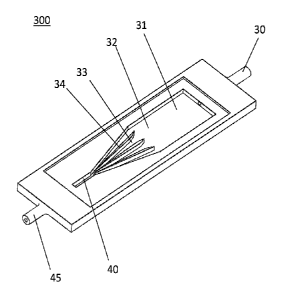
the distal end of the plurality. This configuration facilitates accumulation
of liquid within
channels 33 near the distal end of the channels.
[0042] In an exemplary fluid collection method using device 200, fluid
comprising a mixture of
liquid and air enters the device at reservoir 31. The fluid is then drawn to
channels 33 formed
by channel dividers 34, where liquid from the fluid accumulates at the distal
end of the channels
due to the capillary force provided by the reducing section of the channels
33. Liquid
accumulates in the channels 33 while continuing to allow air to pass through
the remaining open
channels. Periodically, all of the fluid channel 33 become blocked with liquid
and as further air
or fluid is drawn into the fluid collation device, this air or fluid drives
the accumulated liquid
forward to liquid collection region 40, where the liquid is then drawn along
the tube section 37
as a slug of liquid 41. This cycle repeats such that air drawn into the
device, for example, in
NPWT from the dressing and/or any other system leaks, separated successive
fluid slugs 41 and
42. By timing the start 36, 38 and end 35, 39 of the slugs, both the speed and
length of the slugs
can be deteimined. Knowledge of the cross sectional area of the tube section
37 then allows a
volumetric flow to be calculated.
[0043] An isometric representation of an exemplary fluid collection device is
shown in FIG. 3.
Positioned at the proximal end of device 300 is reservoir 31, which receives
fluid through the
inlet 30 of the device housing. Positioned at the distal end of device 300 is
a liquid collection
region 40, which releases slugs of liquid collected within region 40 to outlet
45. Positioned
between reservoir 31 and liquid collection region 40 are three channel
dividers 34, which define
four channels 33 having a proximal end 32 in communication with reservoir 31,
and a distal end
in communication with liquid collection region 40. In an exemplary method for
fluid collection
using device 300, fluid comprising liquid and air enters the device housing at
inlet 30 and then
collects in reservoir 31. As fluid is drawn from the reservoir 31 through the
device, liquid from
the fluid accumulates within channels 33, while air from the fluid bypasses
the channels and
passes through outlet 45. Liquid gradually fills channels 33 until there is no
channel open for air
to pass through. The accumulated liquid is forced to liquid collection region
40 as fluid
continues to enter the housing. The liquid collected in region 40 is released
from the device
- 16 -
CA 03030153 2019-01-07
WO 2018/009879 PCT/US2017/041216
through outlet 45 and into a conduit for detection by one or more sensors as
described elsewhere
herein.
Flow Sensors
[0044] Liquid collected as a slug using a fluid collection device described
herein may be
detected by one or more flow sensors. In some embodiments, a flow sensor is
housed within a
durable or reusable portion of a system that can be used with more than one
fluid collection
device over time. As a non-limiting example, a flow sensor is housed in a main
unit of a
negative pressure system, the main unit comprising the source of negative
pressure and
optionally one or more additional elements, including pressure sensors. In
some embodiments, a
flow sensor is an infrared sensor known and available to one of skill in the
art. As a non-
limiting example a flow sensor is an infrared sensor such as a reflective
optical sensor.
Particular examples of reflective optical sensors include those made by
Broadcom, part number
HSDL-9100-024. Such sensors combine an analogue-output reflective sensor with
an IR emitter
and photodiode. These sensors have a typical rise time of 5Ons and typical
fall time of 5Ons,
which minimizes timing delays to detecting the start and end of liquid slugs.
Further sensors
available to those of skill in the art include tube sensors, such as those
produced by Optek
Technology, part number 0PB350 Such tube sensors operate for tubing of a
specific size, for
example, 1/8th inch tubing, and operate such that clear liquid present causes
the phototransistor
to sink the maximum current, while dark liquid present causes it to sink the
minimum current.
These sensors may have a slower response time, less than 50 microseconds rise
time and a fall
time in the region of 50 to 250 microseconds, however, still provide a
response time suitable for
use in the methods described herein.
[0045] In one aspect, provided herein is a sensing device for use with a fluid
collection device as
described elsewhere herein. In some embodiments, the sensing device is part of
a main unit of a
negative pressure system, wherein the main unit comprises both a source of
negative pressure
and one or more flow sensors for detecting liquid collected as a slug using a
fluid collection
device. In some embodiments, a sensing device comprises a casing comprising a
source of
negative pressure and one or more flow sensors situated within the casing such
that a material
located outside of the casing is in the field of view of the sensors. A non-
limiting example of a
flow sensor is an infrared sensor. In some cases, the sensing device comprises
a plurality of
flow sensors, the plurality comprising about 2, 3, 4, 5, 6, 7, 8, 9 or 10 flow
sensors. For some
instances where the sensing device comprises two or more flow sensors, a first
flow sensor is
positioned between about 0.5 cm and about 4 cm, or typically about 2 cm from a
second flow
sensor, as measured center-to-center.
- 17 -
CA 03030153 2019-01-07
WO 2018/009879 PCT/US2017/041216
[0046] In some embodiments, the casing comprises a thin layer of plastic
within the field of
view of the flow sensor, Plastics include, polyvinyl chloride, polycarbonate,
high density
polyethylene, polystyrene, and any other plastic having suitable infrared
transmittance at the
frequency where liquid is absorbing. In some embodiments, a casing has a
typical thicknesses
from about 0.1 mm as a film to about 3 mm as a moulding. In some embodiments,
a film
bonded over an open channel is used. In some embodiments, a casing comprises a
moulded
section of about 1 mm to about 1.5mm thickness. In some embodiments, the
casing comprises
one or more windows within the field of view of the flow sensor which can
allow the main
casework to be of an infrared absorbing material and to still provide
visibility of the fluid for the
sensors. The windows can be provided by plastics that are transmissive of
infrared at wave-
numbers between 3000 and 4000 cm1. In some cases, a thickness of the window is
between
about 0.1 mm and about 5 mm, or about 1 to 1.5 mm. In some embodiments, the
window is
comprised of a plastic, for example, polyvinyl chloride, polycarbonate, high
density
polyethylene, polystyrene, or a combination thereof. Alternatively, the window
is an open
window with a transmissive-reflective sensor as known to one of skill in the
art. By way of
example, a Broadcom sensor, part number HSDL-9100-024. The transmissive-
reflective sensor
is positioned either close to the window or fitted into the aperture within
the casework. In some
embodiments, the sensing device further comprises a light source situated
within the interior of
the casing such that the material located outside of the casing is in the path
of the light source.
In many implementations, a sensor and light source are combined as a unit as
described above.
[0047] In some embodiments, the flow sensor is housed with one or more
pressure sensors.
Pressure sensors suitable are known to those of skill in the art. Non-limiting
examples of
pressure sensors include: Omron part number SMPP03, range +/-50kPa; Honeywell,
part number ABP
L LN N 250MD A A 3, range +/-250mbar; and NXP, part number MPXV7025DP, with
range -25kPa to
25 kPa. Fluid sensors then include those as described, such as reflective
optical sensors made by
Broadcom, part number HSDL-9100-024 and Optek Technology, part number 0PB350.
[0048] As a non-limiting example, one of the one or more pressure sensors is
configured to
detect a pressure of a wound environment by measuring a pressure at a first
end of a conduit
positioned within the casing, wherein the second end of the conduit is
positioned at the wound
environment. As another example, one of the one or more pressure sensors is
configured to
detect a pressure of a canister by measuring a pressure at a first end of a
conduit positioned
within the casing, wherein the second end of the conduit is positioned within
the canister; and
wherein the conduit is configured to apply a negative pressure from the source
of negative
pressure to the canister.
- 18 -
CA 03030153 2019-01-07
WO 2018/009879 PCT/US2017/041216
[0049] In some embodiments, the sensing device comprises a controller
configured to control an
amount of negative pressure applied by the source of negative pressure. In
some embodiments,
the source of negative pressure comprises a diaphragm pump Diaphragm pumps are
available
to one of skill in the art and include, by way of example, those provided by
Gardener Denver,
model number 2002, 3003 or 3013; KNF part numbers NMS010S or NMS020S; and
Koge, part
number KPV08A-3A or KPV14A. In some implementations where the sensing device
comprises a pressure sensor, the controller controls the amount of negative
pressure applied by
the source of negative pressure in response to a measurement of pressure by
one or more
pressure sensors. In some embodiments, a sensing device comprises a display
for displaying
one or more parameters of the material corresponding to measurements of the
material taken by
the plurality of infrared sensors. In some embodiments, a sensing device
comprises a power
source for providing power to the source of negative pressure, controller,
display, or a
combination thereof In some embodiments, a sensing device lacks a power source
for powering
the source of negative pressure, controller, display, or a combination
thereof, and the power
source is provided by an external unit connected to the sensing device. As a
non-limiting
example, a connector, such as connector 14 exemplified in FIG. 1, provides the
power source. A
source of power includes a battery, such as an alkaline or lithium ion
battery, for example, a
CR123A cell as provided by manufactures such as Panasonic or Duracell or AA
lithium
batteries such as those supplied by Energiser. In some other cases, a
rechargeable battery is
used, such as a lithium polymer cell as supplied by Panasonic or Sanyo of NIMH
batteries
supplied by companies such as Panasonic and FDK.
[0050] A non-limiting example of a sensing device is shown as the main unit 11
in the system
100 of FIG. 1. Main unit 11 comprises two flow sensors 15 and 17, such as
infrared sensors, a
pump 9, and pressure sensors 10 and 12. Flow sensors 15 and 17 are positioned
adjacent a side
of the unit 11 configured to allow for a material located outside of the
casing to be in the field of
view of, and detected by, the sensors.
Systems and Methods
[0051] In one aspect of the disclosure, provided herein are systems comprising
a fluid collection
device and/or flow sensing device as described herein. In some embodiments,
provided is a
device system comprising the fluid collection device and flow sensing device.
Systems
provided herein may further comprise one or more accessory elements, for
example, elements
useful for performing a negative pressure therapy. In some embodiments, an
accessory
comprises a wound dressing. In some embodiments, an accessory comprises a
collection
canister. In some embodiments, an accessory comprises one or more conduits or
tubings
- 19 -
CA 03030153 2019-01-07
WO 2018/009879 PCT/US2017/041216
configured to connect to the dressing, canister, and/or sensing device. In
some embodiments, an
accessory comprises a connector configured to connect the dressing to a
collection canister,
connect the collection canister to the sensing device, and connect the
dressing to the sensing
device.
[0052] In some embodiments, provided herein is a system comprising a fluid
collection device
and a fluid collection canister. The fluid collection device may be an
integral component of the
collection device, or operably connected to the collection device via one or
more connectors
and/or tubings. The fluid collection device can be formed as a combination of
an open channel
moulded into the top of the canister and sealed by a film. Alternatively the
fluid collection
device is built into the connector that connects the dressing to the main unit
and the fluid
channel can be made from two or more moulded components bonded or sealed
together by
adhesive, sealant or welding. Similarly, the fluid channel can be formed by a
thin film bonded
to cover and seal an open channel. The outward (distal) end of the fluid
collection device is then
connected to the canister via a sealed connection provided by means such as an
0 ring seal or
face seal.
[0053] In some embodiments, provided herein is a fluid flow sensing system
comprising a fluid
collection device, a canister, and a sensing device. The fluid collection
device of the fluid flow
sensing system comprises a housing having an inlet located at a proximal end
of the fluid
collection device and an outlet located at a distal end of the fluid
collection device, the interior
of the housing comprising. a reservoir, a plurality of channel dividers
defining a plurality of
fluid channels, and a liquid collection region; wherein the housing comprises
one or more fluid
passageways connecting the inlet and the outlet through the interior of the
housing; and wherein
the reservoir, the plurality of channels, and the liquid collection region are
in fluid
communication within the one or more fluid passageways in the housing. The
canister of the
fluid flow sensing system comprises an inlet and an outlet, the inlet of the
canister in fluid
communication with the outlet of the fluid collection device housing via a
detection conduit. In
some fluid flow sensing systems, the fluid collection device is integral with
the canister. The
sensing device of the fluid flow sensing system comprises a casing having an
inlet, a source of
negative pressure and a plurality of sensors; the inlet of the sensing device
casing in fluid
communication with the outlet of the canister via a negative pressure conduit.
In some fluid
flow sensing systems, the source of negative pressure comprises a diaphragm
pump. In some
cases, the plurality of sensors comprises from about 2 to about 5 flow sensors
An exemplary
flow sensor is an infrared sensor. In some cases, the plurality of flow
sensors comprises two
infrared sensors.
- 20 -
CA 03030153 2019-01-07
WO 2018/009879 PCT/US2017/041216
[0054] In some embodiments, the fluid flow sensing system further comprises a
connector. The
connector may house at least a portion of the negative pressure conduit. In
some cases, the
connector comprises a power source for providing power to the source of
negative pressure.
[0055] In some embodiments, the detection conduit comprises plastic material,
such as
polyvinyl chloride, polycarbonate, high density polyethylene, polystyrene, or
a combination
thereof. In some embodiments, the conduit has a thickness of about 0.1 mm to
about 3 mm, or
typically about 0.1 mm thick if a film of plastic is used and about 0.5 mm to
1.5 mm thick if a
moulded wall is used. In some embodiments, the detection conduit has an inner
diameter of less
than or equal to about 5 mm, or typically about 1 to 3 mm. In some
embodiments, the volume of
the slug to be detected is between about 10 uL and about 3000 uL, or typically
about 30 uL. In
some embodiments, the length of the slug to be detected is between about 1 mm
and about 100
mm, or typically between about 20 mm and 80 mm.
[0056] In some embodiments, the sensing device further comprises a pressure
sensor. For some
methods employing the fluid flow sensing system, application of negative
pressure from the
source of negative pressure is modulated to maintain a predetermined pressure
within the
negative pressure conduit.
[0057] The fluid collection device of the flow sensing system may be
configured and sized as
appropriate to enable the collection of liquid from a fluid mixture of liquid
and air. As a non-
limiting example, the fluid collection device comprises from about 3 to about
8 channel dividers
defining from about 4 to about 9 channels for accumulating fluid prior to
fluid collection and
release as a slug of liquid. In some embodiments, the plurality of fluid
channels is configured to
accumulate between about 20 uL and about 300 uL of liquid. In some cases, the
length of one or
more of the plurality of channel dividers is between about 0.5 cm and about 2
cm. In some
embodiments, the height of one or more of the plurality of channel dividers is
between about 0.5
mm and about 2 mm. In some embodiments, the width of one or more of the
plurality of
channels is between about 0.5 mm and about 2 mm. In some embodiments, the
fluid collection
device is tapered and a proximal end of the reservoir has a width greater than
the width of a
distal end of the liquid collection region. In some embodiments, the width of
the proximal end
of the reservoir is at least about 5x the width of the distal end of the
liquid collection region. As
a non-limiting example, the width of the liquid collection region is between
about 5 mm and
about 20 mm. In some cases, the length of the reservoir is between about 0.5
cm and about 3
cm In some embodiments, the height of the reservoir is between about 1 mm
and about 2 mm.
In some embodiments, the housing comprises a plastic material.
[0058] In some embodiments, the casing of the sensing device comprises a thin
layer of plastic
material so that a flow sensor positioned next to the thin layer of plastic
material detects a slug
- 21 -
CA 03030153 2019-01-07
WO 2018/009879 PCT/US2017/041216
located on the other side of the thin layer of plastic material. In general,
depending on the
particular sensor selected, the distance between the sensor and fluid conduit
should be sized to
match the sensor. Some sensors are set for detection distances of a few
millimeters (1 to 5mm)
and others are set for longer ranges not limited to 50mm. In some embodiments,
the sensing
device further comprises a light source situated within the interior of the
casing such that the
slug is in the path of the light source. In some embodiments, the sensing
device further
comprises a controller configured to control the amount of negative pressure
applied by the
source of negative pressure. As a non-limiting example, the controller
controls the amount of
negative pressure applied by the source of negative pressure in response to a
measurement of
pressure. In some embodiments, the sensing device further comprises a display
for displaying
one or more parameters of the slug corresponding to measurements of the slug
taken by the
plurality of sensors. In some embodiments, the sensing device further
comprises a power
source. In further embodiments, the sensing device does not comprise a power
source and
power is supplied to the sensing device by an external unit connected to the
sensing device.
100591 A non-limiting method for sensing fluid using a fluid flow sensing
system comprises
applying a negative pressure from the source of negative pressure to the fluid
collection device
via the canister to draw a fluid mixture of liquid and air through the inlet
of the fluid collection
device and along the one or more fluid passageways of the fluid collection
device housing;
wherein the liquid of the fluid mixture accumulates at the plurality of flow
channels while the air
of the fluid mixture passes through flow channels until the plurality of flow
channels have
accumulated liquid of the fluid mixture; drawing the accumulated fluid into
the liquid collection
region as a slug of liquid when the plurality of flow channels become blocked
with the
accumulated fluid; drawing the slug from the liquid collection region, through
the outlet of the
fluid collection housing, and through the detection conduit; and detecting
passage of the slug
through the detection conduit with the plurality of sensors. In some
embodiments, the fluid
provided to the fluid collection apparatus comprises less than or greater than
about 5% of air by
volume. In other embodiments the fluid provided to the fluid collection
apparatus comprises less
than or greater than about 1% of liquid by volume. For applications of NPWT,
the ratio of the
percentage of air to liquid depending on the ratio of exudates flow from the
patient and the rate
of air leak into the dressing. Suitable negative pressures applied in such a
method include
pressures between about 80 and about 125 mmHg below atmospheric pressure.
[0060] In some embodiments, the time it takes for the beginning of the slug to
reach each of the
plurality of sensors is detected successively; and the time it takes for the
end of the slug to reach
each of the plurality of sensors is detected successively. Some methods
comprise comparing the
time delay between the beginning and the end of the liquid slug passing the
plurality of sensors
- 22 -
CA 03030153 2019-01-07
WO 2018/009879 PCT/US2017/041216
to calculate the speed and length of the slug. The rate of the flow of the
mixture from the fluid
collection device can also then be calculated.
[0061] The method for sensing fluid flow may be performed as part of a
negative pressure
wound therapy, where the fluid drawn to the canister is exudate from the wound
of a patient and
the inlet of fluid collection device is fluidically connected to the wound
site of the patient via a
wound conduit. In some methods, the canister is positioned relative to the
patient in an
orientation-independent manner.
EXAMPLES
Example 1: Fluid Collection Device
[0062] A fluid collection device as generally shown by 2 was manufactured.
Positioned at the
proximal end of the device is a reservoir having a 15-20 mm width and 15-30 mm
length, and
configured to receive through an inlet of the device. Positioned at the distal
end of the device is
a liquid collection region having a 1-10 mm length, 0.5-8 mm proximal width,
0.5-7 mm distal
width, and configured to releases slugs of liquid collected within this region
to a tube.
Positioned between the reservoir and liquid collection region are four channel
dividers defining
five channels. Each flow divider is 0.1-5 mm in width, defining channels
having 0.1-5 mm
widths. The dividers are tapered to 1-20 degrees, so that the proximal end of
the plurality is
wider than the distal end of the plurality. This configuration facilitates
accumulation of liquid
within the channels near the distal end of the channels. The overall length of
the device is 75
mm, with a 30 mm width.
Example 2: Flow Sensing
[0063] The fluid collection device of Example 1 was used to collect slugs of
liquid from a fluid
input comprising a mixture of fluid and air. The nominal flow of liquid was
set to 3 cc per
minute and an air flow of 10 cc per minute was mixed with the liquid so that a
two phase flow
was established. When the slugs were collated by the device of Example 1, they
were passed
through a detection conduit where they were detected by a pair of infrared
sensors. The infrared
sensors were of the type made by Optek Technology, part number 0PB350 and the
pair of
sensors were placed 50 mm apart.
[0064] FIG. 4 shows graphs of response signals from the two sensors as the
slugs passed
through the detection conduit for 1 min. FIG. 5 shows graphs of response
signals from the two
sensors as the slugs passed through the detection conduit for 15 min. FIG. 6
shows graphs of
processed response signals from the graphs of Figure 5. FIG. 7 shows a section
of the processed
response signal from the graphs of FIG. 6, indicating when flow was detected.
FIG. 8 shows
- 23 -
CA 03030153 2019-01-07
WO 2018/009879 PCT/US2017/041216
graphs plotting the mass of liquid detected flowing through the detection
conduit as a function of
time in minutes, and the nominal mass of liquid actually flowing through the
detection conduit
as a function of time in minutes
[0065] While preferred embodiments of the present disclosure have been shown
and described
herein, it will be obvious to those skilled in the art that such embodiments
are provided by way
of example only. Numerous variations, changes, and substitutions will now
occur to those
skilled in the art without departing from the invention. It should be
understood that various
alternatives to the embodiments of the inventions described herein may be
employed in
practicing the inventions. It is intended that the following claims define a
scope of the
inventions and that methods and structures within the scope of these claims
and their equivalents
be covered thereby.
- 24 -