Note: Descriptions are shown in the official language in which they were submitted.
CA 03030389 2019-01-09
WO 2018/013306
PCT/US2017/038497
1
CONDITIONING A SAMPLE TAKEN FROM A HYDROCARBON STREAM
Field of the Invention
The present invention relates to a process for analysing a hydrocarbon stream.
In
particular, the present invention relates to a process for the on-line
analysis of a
hydrocarbon stream, e.g. a crude oil stream, in which a hydrocarbon sample is
passed
around a sample loop. The process may be used as part of a process for
controlling, e.g.
optimising, a large-scale refinery operation such as a desalting operation.
Back2round of the Invention
When crude oil is extracted from a reservoir, it contains water and salts. At
the high
temperatures that may be encountered in a refinery during crude oil
processing, the water
can hydrolyse the salts to form corrosive acids. Chloride salts are typically
found in crude
oil and pose a particular problem, since they can form hydrochloric acid.
Bromide salts
can also be found, and they can form hydrobromic acid.
Over time, corrosive acids can cause significant damage to refinery equipment.
Damage is commonly observed in the lines that transport crude oil from one
area of a
refinery to another. Considerable time and cost may be involved in replacing
damaged
refinery equipment. In some cases, for instance where a bypass pipe has not
been
provided, processing of the crude oil will need to be stopped entirely in
order for the
refinery equipment to be replaced.
It is therefore desirable for salts to be removed from hydrocarbon fluids such
as
crude oil before refinery processing. To solve this problem, crude oils are
passed to a
desalter before they are processed in a refinery.
Crude oils are typically mixed with wash water before they are passed to the
desalter.
Once introduced into the desalter, a desalted crude oil phase and an aqueous
phase form.
The aqueous phase contains water (that which was present in the extracted
crude oil, as
well as water that has been added to the hydrocarbon stream during processing,
such as
wash water) and salt. A rag layer separates the two phases. The rag layer is a
mixture of
the aqueous phase and the desalted crude oil phase.
A desalted crude oil stream and an aqueous stream are withdrawn from the
desalter
through separate lines. The streams are typically withdrawn at points in the
desalter which
CA 03030389 2019-01-09
WO 2018/013306
PCT/US2017/038497
2
are a distance from the rag layer so as to minimise the presence of any
aqueous
components in the desalted crude oil stream and vice versa.
Methods are known for optimising desalting processes. For instance,
demulsifiers
are often added to minimise the rag layer and encourage the formation of
separate
.. hydrocarbon and aqueous phases. The application of an electrostatic field
to the desalting
unit may also be used to encourage the formation of separate phases.
However, the optimal conditions for operating a desalting process, and indeed
for
optimising other refinery processes, can vary greatly depending on the
composition of the
crude oil. It is therefore desirable to sample a crude oil before it is passed
to a refinery
.. process, such as a desalting process. This enables the refinery process to
be optimised
based on the particular crude oil that is being used.
Whilst crude oil may be sampled and tested before it is passed to the
refinery,
sometimes even before purchase, it is preferable to carry out on-line analysis
of the crude
oil. This analysis is often done using a sample loop in which a sample of
crude oil is
withdrawn from a process stream, analysed, and return to the process stream.
For example, GB 2170909 discloses a method for the on-line monitoring of crude
oil
in which a sample is isolated and circulated around a sample loop which
includes a heat
exchanger and a densitometer.
US 8,497,683 discloses a spectroscopic sample analysis apparatus which
includes an
actively controlled heat exchanger in serial fluid communication with a
spectroscopic
analyzer, and a controller communicably coupled to the heat exchanger. The
apparatus
may be used to measure properties of the samples by spectroscopic methods,
such as
nuclear magnetic resonance, infrared, near infrared and Raman spectroscopy.
However, existing methods for the on-line sampling of crude oil suffer from a
number of drawbacks. In particular, fouling of the sample loop can occur over
time, e.g.
around the analysis device, thereby reducing the accuracy of the crude oil
analysis. This
fouling has previously been thought to be caused by inorganic compounds. To
protect the
analysis device from inorganic solids, the crude oil is often passed through a
filter before it
is passed to the analysis device. However, in severe cases of fouling, filters
in the sample
loop may become plugged, preventing any analysis at all. As a consequence,
optimisation
of the refinery process to which the crude oil is passed may be compromised.
CA 03030389 2019-01-09
WO 2018/013306
PCT/US2017/038497
3
Accordingly, there is a need for an improved method for the on-line analysis
of a
refinery feedstock, such as a crude oil. There is also a need for an improved
method for
controlling a refinery process, such as a desalting process.
Summary of the Invention
It has now surprisingly been found that fouling of a sample loop may be caused
by
waxes that are present in hydrocarbon fluids such as crude oils. This is in
contrast to the
previously held belief that it is the inorganic compounds that are present in
crude oil, such
as iron sulfide, that are principally responsible for fouling. It has further
been found that
the deposition of waxes may be prevented by conditioning the hydrocarbon fluid
so that it
is passed around at least part of the sample loop, e.g. those areas most prone
to fouling, at a
temperature of greater than 120 C and a flow rate of greater than 20 litres
per minute.
Accordingly, the present invention provides a process for analysing a
hydrocarbon
stream, said process comprising:
withdrawing a hydrocarbon sample from a hydrocarbon stream;
passing the hydrocarbon sample to an analysis device at a target temperature
of
greater than 120 C and a target flow rate of greater than 20 litres per
minute; and
returning the hydrocarbon sample to the hydrocarbon stream.
Also provided is a process for controlling a refinery operation, said process
comprising:
analysing a hydrocarbon stream which is a feedstock for, or a product stream
from,
the refinery operation using the process disclosed herein; and
based on the analysis, modifying or maintaining the conditions under which the
hydrocarbon stream is processed in the refinery operation.
Brief Description of the Drawings
.. Fig. 1 is a schematic diagram of a sample loop which may be used in
accordance with the
present invention; and
Fig. 2 shows an image of wax fouling on a 100 p.m filter, caused by contacting
2000 mL of
crude oil with the filter at 60 C.
Detailed Description of the Invention
The process of the present invention involves withdrawing a hydrocarbon sample
from a hydrocarbon stream, analysing the sample and returning the hydrocarbon
sample to
the hydrocarbon stream. Thus, the process of the present invention involves
passing a
CA 03030389 2019-01-09
WO 2018/013306
PCT/US2017/038497
4
hydrocarbon sample around a sample loop. The present invention involves
conditioning
the hydrocarbon sample so that it is passed to the analysis device at an
optimal temperature
and flow for reducing fouling.
Accordingly, the process disclosed herein may be used to reduce fouling, e.g.
caused
by waxes (e.g. alone or in combination with asphaltenes and/or inorganic
solids such as
iron sulfide), in a hydrocarbon sample loop.
Withdrawing a hydrocarbon sample from a hydrocarbon stream
The process of the present invention includes the step of withdrawing a
hydrocarbon
sample from a hydrocarbon stream. It will be appreciated that the hydrocarbon
sample will
generally be in the form of a sub-stream. Generally, less than 10 %,
preferably less than 5
%, and more preferably less than 1 % by volume of the hydrocarbon stream will
be
withdrawn as the hydrocarbon sample.
The hydrocarbon stream preferably comprises waxes in an amount of greater than
0.1
%, more preferably greater than 0.5 %, and still more preferably greater than
1 % by
weight of hydrocarbon stream. The hydrocarbon stream will generally comprise
waxes in
an amount of less than 25 % by weight of hydrocarbon stream. The wax content
of the
hydrocarbon stream may be measured according to UOP 46-64 or ASTM D2500, and
preferably according to ASTM D2500-16. NMR methods may also be used to monitor
wax content.
The hydrocarbon stream preferably comprises asphaltenes in an amount of
greater
than 0.1 %, more preferably greater than 2 %, and still more preferably
greater than 5 %,
by weight of hydrocarbon stream. The asphaltene content of the hydrocarbon
stream may
be measured according to ASTM D6560-12. In addition to the waxes that are
present in
the hydrocarbon stream, asphaltenes may contribute to fouling of the sample
loop.
The hydrocarbon stream may also comprise inorganic compounds. In preferred
embodiments, the hydrocarbon stream comprises iron sulphide, though the
hydrocarbon
stream may also comprise clays and calcium carbonates. Inorganic compounds may
also
contribute to fouling in the sample loop.
The hydrocarbon stream is preferably a crude oil stream. In these embodiments,
the
sample withdrawn from the hydrocarbon stream will be a crude oil sample. Since
crude oil
contains heavy components, such as waxes and asphaltenes, as well as inorganic
components, such as iron sulfide, it is prone to fouling when passed through a
sample loop.
CA 03030389 2019-01-09
WO 2018/013306
PCT/US2017/038497
Heavier crude oils, i.e. those having a higher content of asphaltenes and
waxes, are
particularly prone to fouling.
The crude oil stream may be a crude oil stream that is being passed through a
production pipeline, a transportation pipeline or a processing pipeline.
Preferably the
5 crude oil stream is being passed through a processing pipeline, i.e. it
forms part of a
refinery apparatus.
In some embodiments, the crude oil may be a raw crude oil (also known as a
dead
oil, or a stock tank oil). Raw crude oil may be obtained by bringing crude oil
from a
subterranean formation (i.e. a live oil) to atmospheric conditions, for
instance of 20 C and
100 kPa. Gases that are dissolved in the live oil under subterranean
conditions are
removed during this process. It will be appreciated that the raw crude oil is
used at non-
atmospheric conditions during the processes disclosed herein.
Preferably, a sample of the raw crude oil is withdrawn from the crude oil
stream
before wash water is added thereto, e.g. wash water that may be used in a
desalting
.. process.
The raw crude oil is preferably sampled after the crude oil stream has been
subjected
to heating, e.g. in a preheat train. This reduces the energy input that is
required to maintain
the temperature of the crude oil sample in the sample loop.
In other embodiments, the crude oil stream may be a desalted crude oil stream.
Desalted crude oil streams will generally be at a higher temperature than raw
crude oil
streams, and so less energy input may be required in the sample loop.
The hydrocarbon sample may be withdrawn from the hydrocarbon stream
continuously. However, it is generally preferred for the hydrocarbon sample to
be
withdrawn from the hydrocarbon stream intermittently. Valves may be used to
control the
withdrawal of the hydrocarbon sample from the hydrocarbon stream.
Passing the hydrocarbon sample to an analysis device
The hydrocarbon sample is passed to an analysis device at a target temperature
of
greater than 120 C and a target flow rate of greater than 20 litres per
minute. As
mentioned above, these conditions are believed to minimise fouling and
plugging around
the analysis device.
The hydrocarbon sample is passed to the analysis device at a target flow rate
of
greater than 20 litres per minute. Preferably, the hydrocarbon sample is
passed to the
CA 03030389 2019-01-09
WO 2018/013306
PCT/US2017/038497
6
analysis device at a target flow rate of greater than 25 litres per minute,
and more
preferably greater than 30 litres per minute. By keeping the sample flowing at
a fast rate,
fouling of the sample loop with waxes is avoided. The hydrocarbon sample may
be passed
to the analysis device at a target flow rate of less than 90 litres per
minute, preferably less
than 75 litres per minute, and more preferably less than 60 litres per minute.
For example,
the hydrocarbon sample may be passed to the analysis device at a target flow
rate of from
35 to 40 litres per minute.
The hydrocarbon sample may be passed to the analysis device at a target
velocity of
greater than 0.5 m/s, preferably greater than 1 m/s, and more preferably
greater than 2 m/s.
By maintaining the sample at a relatively high target velocity, the waxes are
prevented
from plugging the sample loop. The hydrocarbon sample is preferably passed to
the
analysis device at a target velocity of less than 6 m/s, and more preferably
less than 5 m/s,
since higher velocities may not be compatible with the analysis device.
The flow rate of the hydrocarbon sample may be achieved by conventional means,
such as by using one or more pumps. However, the flow rate is preferably
controlled using
piping of an appropriate size, shape and length. The flow rate may also be
controlled
through back pressure control, the use of orifice restrictions, and the use of
by-passes. In
preferred embodiments, the flow rate of the sample is monitored (and, where
necessary,
controlled) to ensure that the target flow rate has been achieved. The
velocity of the
hydrocarbon sample may also be achieved, controlled and monitored in the same
way, e.g.
to ensure that the target velocity has been reached.
Preferably, the piping through which the hydrocarbon sample is passed in the
sample
loop has a length of less than 50 m, preferably less than 40 m, and more
preferably less
than 30 m. Preferably the piping has a diameter of from 0.5 to 2 cm, and more
preferably
.. from 0.8 to 1.3 cm. The piping is preferably stainless steel tubing.
The hydrocarbon sample is passed to the analysis device at a target
temperature of
greater than 120 C. Preferably, the hydrocarbon sample is passed to the
analysis device at
a target temperature of greater than 130 C, and more preferably greater than
135 C.
Whilst an increase in temperature reduces the deposition of waxes, higher
temperatures
may reduce the viscosity of the sample causing deposition of inorganic solids
in the sample
loop. Accordingly, the hydrocarbon sample is preferably passed to the analysis
device at a
target temperature of less than 190 C, more preferably less than 180 C, and
still more
CA 03030389 2019-01-09
WO 2018/013306
PCT/US2017/038497
7
preferably less than 175 C. For example, the hydrocarbon sample may be passed
to the
analysis device at a target temperature of from 140 to 170 C. It is
surprising that these
temperatures are sufficient to reduce fouling of waxes, whilst still
minimizing fouling
caused by inorganic solids.
The target temperature may be achieved by heating the hydrocarbon sample.
Suitable methods for heating the hydrocarbon sample may involve steam cool
heaters,
electric heat tracing, steam tracing, electric coil heaters and combinations
thereof
Insulation may also be used to minimise heat loss from the hydrocarbon sample.
For
instance, cladding may be used around the piping through which the hydrocarbon
sample is
passed in the sample loop.
In preferred embodiments, the process of the present invention involves
monitoring
the temperature of the hydrocarbon sample and, if the temperature of the
hydrocarbon
sample falls below the target temperature, heating the hydrocarbon sample.
Thus, a
temperature detection device may be used which provides feedback to a heating
device.
The temperature detection and the heating device are preferably positioned
between
the point at which the hydrocarbon sample is withdrawn from the hydrocarbon
stream and
the analysis device. The heating device may be positioned between the point at
which the
hydrocarbon sample is withdrawn from the hydrocarbon stream and the
temperature
detection device, or it may be positioned between the temperature detection
device and the
analysis device. In some embodiments, a heating device will be positioned
between the
point at which the hydrocarbon sample is withdrawn from the hydrocarbon stream
and the
temperature detection device, and between the temperature detection device and
the
analysis device. In embodiments, a plurality of temperature detection devices
and a
plurality of heating devices are positioned between the point at which the
hydrocarbon
sample is withdrawn from the hydrocarbon stream and the analysis device.
The input of heat required to achieve the target temperature will be directly
dependent on the original sample temperature. Raw crude oil will generally
require much
more heat input than desalted crude, particularly if it is withdrawn from a
crude oil stream
before the preheat train. Typically, the temperature of raw crude oil on
withdrawal from
the crude oil stream will be around 90 C or greater, whereas the temperature
of desalted
crude oil will be around 110 C or greater.
CA 03030389 2019-01-09
WO 2018/013306
PCT/US2017/038497
8
The hydrocarbon sample will generally be passed to the analysis device (and
preferably maintained throughout the sample loop) below its flash point. The
process of
the present invention may therefore comprise pressurising the hydrocarbon
sample before
it is passed to the analysis device. This prevents the more volatile
components in the
hydrocarbon sample from flashing off when heat is applied. The hydrocarbon
sample may
be passed to the analysis device at a target pressure of from 200 to 1500 KPa,
preferably
from 250 to 1250 KPa, and more preferably from 400 to 1000 KPa.
The analysis device may be used to measure a chemical or physical property of
the
hydrocarbon stream, or combinations thereof
Suitable properties may be selected from chlorine content, sulfur content,
water
content, density, viscosity and content of metal elements (e.g. calcium, iron,
nickel, and
vanadium content).
Suitable analysis devices include x-ray diffraction (XRD) devices (e.g. to
measure
the chlorine content, sulfur content and content of metal elements), microwave
detection
devices (e.g. to measure water content), and a Coriolis flow meter or a
densitometer (e.g. to
measure density and viscosity).
Preferably, the analysis device measures the chlorine content of the
hydrocarbon
sample. Examples of suitable XRD devices for measuring the chlorine content of
the
hydrocarbon sample include Clora 0 devices provided by X-Ray Optical Systems
(known
as XOS). This embodiment is particularly preferred where the hydrocarbon
stream is a
feedstock to, or a product stream from, a desalter, since it enables the
conditions in the
desalter to be modified or maintained in order to optimise the desalting
process.
The hydrocarbon sample may be passed to a single analysis device, or it may be
passed to at least two analysis devices. In some embodiments, the hydrocarbon
sample
may be passed to at least two analysis devices in series. In other
embodiments, the
hydrocarbon sample may be separated into sub-samples, with each of the sub-
samples
passed to an analysis device in parallel.
The hydrocarbon sample is preferably filtered before it is passed to the
analysis
device. This enables solids to be removed from the hydrocarbon sample before
it is
analysed.
The filter may have a mesh size of from 25 to 2000 p.m, preferably from 50 to
1000
p.m, and more preferably from 80 to 500 p.m.
CA 03030389 2019-01-09
WO 2018/013306
PCT/US2017/038497
9
To minimise fouling of the filter, the hydrocarbon sample is preferably
filtered at the
target temperature and the target flow rate. The hydrocarbon sample is
preferably also
maintained at the target temperature and the target flow rate between the
filter and the
analysis device. The hydrocarbon sample is also preferably filtered, and
preferably
maintained between the filter and the analysis device, at the target velocity
and/or target
pressure.
Whilst maintaining the hydrocarbon sample at the target temperature and the
target
flow rate (and other optional target conditions, such as target velocity and
target pressure)
reduces the degree of fouling that takes place in the sample loop, some
fouling may still
occur. Accordingly, in preferred embodiments, any filters that are used are
subjected to
backwashing, i.e. a process in which a backwash medium is passed through a
filter in the
opposite direction to which the hydrocarbon sample is passed through the
filter.
The backwash medium is preferably maintained at the target temperature of the
hydrocarbon sample.
The backwash medium may be any suitable fluid, such as a hydrocarbon fluid
(e.g.
crude oil or diesel) or nitrogen. The backwash medium is preferably the same
fluid as that
of the hydrocarbon stream and hydrocarbon sample. In these embodiments, the
backwash
medium may be withdrawn from the hydrocarbon stream.
Returning the hydrocarbon sample to the hydrocarbon stream
Once the hydrocarbon sample has been passed to, and analysed using, the
analysis
device, it is returned to the hydrocarbon stream.
The hydrocarbon sample may be filtered after it has been passed to the
analysis
device but before it is returned to the hydrocarbon stream. The filter may
have a mesh size
of from 25 to 2000 um, preferably from 50 to 1000 um, and more preferably from
75 to
.. 500 um.
As with the filter before the analysis device, the hydrocarbon sample is
preferably
filtered at the target temperature and the target flow rate, and more
preferably maintained
at the target temperature and the target flow rate between the analysis device
and the filter.
The hydrocarbon sample is also preferably maintained between the analysis
device and the
.. filter, and preferably filtered, at the target velocity and/or target
pressure.
In embodiments where the hydrocarbon sample has been pressurised, the
hydrocarbon sample may be depressurised before it is returned to the
hydrocarbon stream.
CA 03030389 2019-01-09
WO 2018/013306
PCT/US2017/038497
Accordingly, in some embodiments, the process of the present invention
involves
pressuring the hydrocarbon sample, passing the pressurised hydrocarbon sample
to the
analysis device, depressurising the hydrocarbon sample, and returning the
depressurised
hydrocarbon sample to the hydrocarbon stream.
5 Alternatively, e.g. where the crude sample is raw crude oil, it may be
returned to the
raw crude oil stream downstream of the mix valve in a two-stage desalter
without being
depressurised.
Where the hydrocarbon sample is withdrawn from the hydrocarbon stream
intermittently, valves may be used to control the return of the hydrocarbon
sample to the
10 hydrocarbon stream.
Use of a sample loop for adjusting hydrocarbon stream processing conditions
The process of the present invention may be used as part of a process for
controlling
a refinery operation. According to the process, a hydrocarbon stream which is
a feedstock
for, or a product stream from, the refinery operation is analysed using a
process disclosed
.. herein. Based on the analysis, the conditions under which the hydrocarbon
stream is
processed in the refinery operation may be modified or maintained.
In preferred embodiments, the refinery operation is a desalting operation that
is
carried out in a desalting unit. In these embodiments, crude oil is preferably
used as the
feedstock for, or the product stream from, the desalting operation, and the
chlorine content
of the feedstock is preferably measured.
Any conventional desalting unit may be used in the invention. A desalting unit
will
typically have an inlet, a hydrocarbon outlet and an aqueous outlet. In the
process of the
invention, the hydrocarbon stream, water and salt are introduced into the
desalter via the
inlet. A hydrocarbon phase is removed from the desalter via the hydrocarbon
outlet. An
aqueous phase is removed from the desalter via the aqueous outlet.
The conditions under which the desalter is operated may be modified or
maintained
based on the chlorine content of the crude oil. Preferably, the conditions are
modified. For
instance, the following conditions of the desalting operation may be modified:
the amount
of wash water that is added to the feedstock, the amount or type of additives
(such as
demulsifiers) that are added to the feedstock, the degree of mixing that the
feedstock and
wash water and/or additives are subjected to before introduction into the
desalting unit, the
CA 03030389 2019-01-09
WO 2018/013306
PCT/US2017/038497
11
temperature in the desalting unit, the pressure in the desalting unit, and the
electrostatic
field that is applied in the desalting unit.
The process for controlling the desalting operation may be used to optimise
the
desalting operation. In some instances, the process of the present invention
optimises
desalting operation by increasing the proportion of salt that is removed from
the
hydrocarbon stream during desalting. An optimised desalting operation
preferably reduces
the total inorganic chloride concentration to less than 5 ppm. Where the
desalting
operation is a two stage process, the total inorganic chloride concentration
may be reduced
to less than 2 ppm. The desalting operation may also be optimised by
improvements in
__ efficiency. Improvements in efficiency include increases in throughput,
decreases in the
energy used to carry out the desalting process and decreases in the cost of
the apparatus
used to carry out the desalting process.
The process of the present invention may also be used optimise refinery
processes
that are found downstream of a desalter and which benefit from an improvement
in the
desalting operation. For example, the processes described herein may be to
reduce furnace
fouling, and to increase the lifetime of catalysts that are found downstream
of a desalter in
a refinery, e.g. catalysts found in process units such as a fluid catalytic
cracking (FCC)
unit.
The invention will now be described with reference to the accompanying non-
limiting figures and examples.
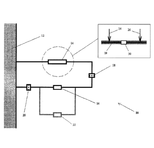
Figure 1 is a diagram of a sample loop (10) for use in accordance with the
process of
the present invention. The sample loop comprises a sample conditioning unit
(14), an
analysis device (16) and two filters (18, 20). The sample conditioning unit
(14) comprises
sensors (24, 26) and a heating device (30). A further analysis device (22) is
shown as part
of an optional sub-loop.
Though only shown in the inset of Figure 1, the tubing through which the
hydrocarbon sample is passed in the sample loop (10) is covered with
insulative cladding
(28). This helps to maintain the hydrocarbon sample at the target temperature.
In use, a hydrocarbon sample is withdrawn from hydrocarbon stream (12) and
passed
to a sample conditioning unit (14). The sensors (24, 26) in the sample
conditioning unit
(14) test the temperature of the hydrocarbon sample, and a heating device (30)
supplies
additional heat to the hydrocarbon sample, if necessary. Sensor (24) is used
to determine
CA 03030389 2019-01-09
WO 2018/013306
PCT/US2017/038497
12
whether additional heat should be added by heating device (30), whilst sensor
(26) is used
to check that sufficient heat has been added.
The hydrocarbon sample is then passed to filter (18) at the target temperature
and
flow rate (though not shown, the sample loop of Figure 1 may comprise means,
e.g.
.. pumps, for maintaining the hydrocarbon sample at the target flow rate). The
filter (18)
removes any larger solid particles, such as any inorganic solids that may be
present in the
hydrocarbon sample.
The hydrocarbon sample is maintained at the target temperature and target flow
rate
as it is passed to the analysis device (16). The sample loop shown in Figure 1
comprises
an optional sub-loop on which a further analysis device (22) is present. Where
the sub-
loop is used, the hydrocarbon sample is separated into sub-samples and passed
to the
analysis devices (16, 22) in parallel.
The hydrocarbon sample is then passed to filter (20) which removes any solids
that
may have formed in the sample loop (10) from the hydrocarbon sample before it
is passed
back to hydrocarbon stream (12).
Examples
Example 1: Evidence that waxes are responsible for fouling
Fresh filters (100 p.m and 120 p.m) were fitted before and after an analysis
device in a
crude oil sample loop. A crude oil sample was originally passed at a flow rate
of greater
__ than 20 litres / minute. The crude oil sample was not subjected to any
heating, and no
insulation was provided to maintain its temperature through the sample loop.
As fouling
occurred on the filters, the flow rate of the crude oil sample around the
sample loop
slowed. As any heat in the sample loop was provided only by the crude oil, the
reduced
flow rate also led to a reduction in the temperature in the sample loop. The
sample loop
failed due to plugging of the filters within a couple of weeks.
Microscopic examination of the filters unexpectedly showed that the majority
of the
fouling was caused by waxes, with minimal inorganic fouling. Although it is
known that
crude oils contain wax, it was surprising that a sufficient amount of wax had
agglomerated
in particulate form to lead to plugging of the filters.
Small-scale tests were also conducted on a 100 p.m filter to confirm the
nature of the
fouling. 2000 mL of crude oil was contacted with the filters at 60 C. Figure
2 shows an
CA 03030389 2019-01-09
WO 2018/013306
PCT/US2017/038497
13
image of a filter after one of the tests. The presence of wax on the filter
can clearly be seen
from in the image.
Example 2: Investigating conditions suitable for reducing the build-up of wax
Small-scale tests were conducted to investigate the effect of temperature on
the
.. fouling of 100 p.m and 120 p.m filters. 20 mL of crude oil was contacted
with the filters at
temperatures ranging from 40 to 95 C. For the 100 p.m filters, higher degrees
of fouling
were observed on the tests run at 40 C and 60 C than the test run at 95 C,
though fouling
was exhibited at all temperatures. Higher degrees of fouling were also
observed on the
tests run at 40 C and 60 C than the test run at 95 C for the 120 p.m
filters. The tests
__ demonstrate that, at 95 C, fouling is reduced but still present on the
filters. Accordingly,
higher crude oil conditioning temperatures, such as a temperature of greater
than 120 C,
are believed to be necessary.
A larger crude oil sample size was used for more accurate testing. 2000 mL of
crude
oil was contacted with 100 p.m filters at 60 C. The filters were then
backwashed with
diesel and dried at 60 C and at 95 C. The results of the experiment are
shown in the
following table:
Backwash Weight of solids (g) .. Solids removed
None 0.0028 0%
60 C diesel 0.0013 53%
95 C diesel 0.0004 86%
It can be seen that backwashing removes some, though not all, of the wax
deposits,
.. with the higher temperature backwash medium removing a higher proportion of
solids.
Accordingly, while backwashing may be a useful tool in removing solids,
prevention of
wax build-up is nonetheless believed to be necessary.
Prevention of wax build-up was proposed by conditioning the hydrocarbon fluid
so
that it is passed through the filters and analysis device at a temperature of
greater than 120
C and a flow rate of greater than 25 litres per minute.
Example 3: Testing the sample conditioning method
A full-scale desalting operation was conducted. A sample loop was used to
withdraw and analyse a sample from a crude oil stream that formed part of the
desalting
operation. The sample was passed through a filter and to the analysis device
at a
CA 03030389 2019-01-09
WO 2018/013306
PCT/US2017/038497
14
temperature of greater than 120 C and a flow rate of greater than 20 litres
per minute.
Reduced plugging of the filter was observed.