Note: Descriptions are shown in the official language in which they were submitted.
CA 03030562 2018-12-13
METALLIC BURNER TILES
FIELD OF THE INVENTION
The present disclosure relates to the field of burners for industrial
applications
particularly applications at temperatures greater than 800 C such as
petrochemicals
processing including cracking of paraffins. In some embodiments the present
disclosure relates to metallic floor or wall burners used in such
applications.
BACKGROUND OF THE INVENTION
The cracking of paraffins such as ethane to olefins such as ethylene is energy
intensive. The paraffin passes through tubes or coils in a furnace with flue
gasses
heated up to about 1200 C. The internal walls of the furnace are refractory
material
which radiates heat to the process coils. The walls are heated by a series of
burners
in the floor or walls or both. The temperature of the walls may reach
temperature in
the range from 700 C to 1350 C, or from 800 C to 1200 C.
Currently, parts of the burner in the interior of the furnace are manufactured
with a refractory material. This makes the burners heavy. Additionally, the
refractory
or ceramic tends to be brittle and can break during transport and operation.
British patent 1,480,150 discloses an improvement relating to high
temperature burners in which a metallic quarl having an inner and outer
surface and
providing a closed chamber surrounds the burner. A cooling medium passes
through the quarl to keep the burner at a lower temperature. The patents
teaches
the cooling medium could be air being fed to the burner or exhaust gasses from
combustion. The reference teaches away from the present disclosure as a double
walled quarl is not used.
The paper Development of Ultra Compact Low NOx Burner for Heating
Furnace in the Proceedings of the 1998 International Gas Research Conference
by
A. Omori of Osaka Gas Co., Ltd. pages 269 ¨ 276 discloses a metal burner. The
burner does not have channels in the interior metal burner walls to pass air
over the
wall and cool the burner. Further the burner is designed to provide a vortex
flow of
air to the flame to increase the surface area and reducing the flame
temperature.
Such a reduction in flame temperature may not be desirable.
United States Patent application 20100021853 published Jan 28, 2010 in the
name of Bussman assigned to John Zink Company LLC. Teaches a burner to
produce low NOx emissions. In the figures the burners are tiles (e.g. ceramic
or
refractory) in which a significant amount of the burner is made of such
materials. In
CA 03030562 2018-12-13
contrast the burners disclosed herein comprise less than 20 wt% of ceramic or
refractory, or for example, no ceramic or refractory. Additionally, if ceramic
or
refractory is used it is over coated on the outside of the metal.
The present disclosure seeks to provide a metallic, or substantially metallic
burner for use in industrial applications such as cracker furnaces.
SUMMARY OF THE INVENTION
The present disclosure provides a substantially metallic burner having a
service temperature of not less than about 1200 C for a cracking furnace
operating
with walls at temperatures from 700 C to 1350 C comprising:
i) a substantially metallic flow passage defined by at least one surface
having a downstream outlet and at least one upstream inlet for at least a
gaseous
oxidant;
ii) said substantially metallic flow passage having at least one
baffle
directing the flow of oxidant and fuel against the internal surface of the
burner facing
.. the furnace; and
ii) optionally one or more arrays of heat convective surfaces selected from
baffles, ribs, fins and protuberances to direct the flow of said at least a
gaseous
oxidant over said one or more arrays on the internal surface of said
substantially
metallic flow passage.
In a further embodiment there is provided a burner having an arrays of heat
convective surfaces that are ribs that define at least one continuous series
of parallel
channels at least on the internal surface of the portions of the burner
exposed to the
cracking furnace.
In a further embodiment there is provided a burner wherein the channels have
a height to width ratio from 0.1 to 2, or from 0.25 to 2, in some embodiments
from 0.5
to 2, in further embodiments from 0.5 to 1.
In a further embodiment there is provided a burner, wherein one or more
metallic fuel line terminate(s) proximate the external front surface for said
flow
passage from 25 to 75% of the height of the front of the flow passage.
In a further embodiment there is provided a burner wherein said at least one
metallic surface has a thickness from 4 to 25 mm
In a further embodiment there is provided a burner comprising in cooperating
arrangement:
CA 03030562 2018-12-13
i) a lower metal flow passage for one or more gaseous oxidants having
an open back end, closed side walls and a closed bottom wall, a front wall and
a top
wall which does not extent the full length of the side walls to define an open
upward
facing vent in the upper front end of the flow passage; and a metal front wall
continuous with the bottom wall of the flow passage;
ii) a metal upper section having the same width as the metal flow
passage comprising a front wall, two parallel side walls and a rear wall
defining a
chamber, an open bottom which co-operates with the open vent in the flow
passage
and a front wall and an open top said front wall and back wall having openings
therein at substantially the same height and lateral displacement to provide
for one
or more fuel supply lines passing from the back to the front of said upper
section;
iii) either:
a) one or more metal, or ceramic coated metal, top plates
cooperating with the open top of the upper metal section, said one or more
top plates having a planar surface optionally having a curved leading edge
and one or more substantially circular passageways there through, said back
section having one or more outlets which may be circular, oval, or polygon
(e.g. triangular, rectangular or square) for said one or more gaseous oxidant
there through; or
b) a continuation of the upper front wall extending to the back wall
of the upper section said continuation having a leading edge optionally curved
and optionally having one or more substantially circular passageways there
through, and a planar back section having one or more outlets which may be
circular, oval, or polygon (e.g. triangular, rectangular or square) for said
one
or more gaseous oxidants there through, said back section optionally being
coated with a ceramic; and
iv) one or more descending baffle extending into said metal upper section.
As used herein planar refers to the degree of curvature of an element. But
the current disclosure is not limited by the shape or geometry of the sides of
the
enclosure (e.g. box). While planar surfaces are exemplified, embodiments where
the
sides of the enclosure are curved or wavy are also envisioned.
In a further embodiment there is provided a burner wherein there is a
descending baffle depending from a region not more than 10% forward of the
forward lip of said one or more outlets for at least a gaseous oxidant, to the
forward
CA 03030562 2018-12-13
lip of said one or more outlets for said one or more gaseous oxidants, said
baffle
descending inside the upper metal section of the burner from 50 to 90% of the
height
of the front face of said burner; and extending laterally across the inner
surface of
the burner from 100 to 75% of the width of the face of said burner, said
descending
baffle being positioned so that there are substantially equal openings on each
side of
the descending baffle relative to the side walls of the metal upper section
and where
necessary said descending baffle having one or more circular channels there
through to permit one or more fuel supply lines to pass there through.
In a further embodiment there is provided a burner having series of parallel
.. longitudinal internal ribs to direct the flow of said at least a gaseous
oxidant over the
forward facing surface of said descending baffle.
In a further embodiment there is provided a burner further comprising an
ascending baffle extending forward from the upper wall of said lower metal
flow
passage into from 45 to 85% of the open area in the chamber of a metal upper
section.
In a further embodiment there is provided a burner wherein said ascending
baffle extending forward from the upper wall of said lower metal flow passage
is bent
in its forward section up towards the open top to provide an upwards facing
ascending baffle parallel to the inner front wall of upper section and where
required
the upward extending section of said ascending baffle having one or more
circular
channels there through to permit one or more fuel supply lines to pass there
through.
In a further embodiment there is provided a burner wherein said ascending
baffle extending forward from the upper wall of said lower metal flow passage
further
comprises on the surface facing the inner front wall of upper section a series
of
.. parallel longitudinal internal ribs to direct the flow of said at least a
gaseous oxidant
over the internal surface of said substantially metallic flow passage.
In a further embodiment there is provided a burner wherein the channels have
a height to width ratio from 0.1 to 2. In some embodiments the ribs may have a
height from 4 to 25 mm, or from 8 to 22 mm, in some instances from 10 to 20
mm.
In a further embodiment there is provided a burner wherein there is an
ascending baffle extending forward from the upper wall of said lower metal
flow
passage into from 45 to 85% of the open area in the chamber of a metal upper
section.
CA 03030562 2018-12-13
In a further embodiment there is provided a burner wherein said ascending
baffle extending forward from the upper wall of said lower metal flow passage
is bent
in its forward section up towards said one or more outlets to provide an
upwards
facing ascending baffle parallel to the inner front wall of upper section and
where
required the upward extending section of said ascending baffle having one or
more
circular channels there through to permit one or more fuel supply lines to
pass there
through.
In a further embodiment there is provided a burner wherein said ascending
baffle extending forward from the upper wall of said lower metal flow passage
further
comprises on the surface facing the inner front wall of upper section a series
of
parallel longitudinal internal ribs to direct the flow of said at least a
gaseous oxidant
over the internal surface of said substantially metallic flow passage.
In a further embodiment there is provided a burner wherein the channels have
a height to width ratio from 0.1 to 2.
In a further embodiment there is provided a burner wherein said one or more
top plates is present and is metal.
In a further embodiment there is provided a burner said one or more top
plates is present and is metal coated with ceramic.
In a further embodiment there is provided a burner wherein the upper front
wall continues to the upper back wall and the back section is not coated with
ceramic.
In a further embodiment there is provided a burner wherein the upper front
wall continues to the upper back wall and the back section is coated with
ceramic.
BRIEF DESCRIPTION OF THE DRAWINGS
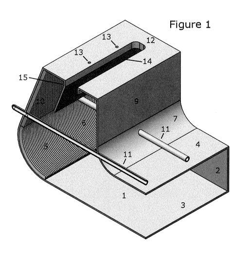
Figure 1 is a cutaway isometric view of one embodiment of a burner according
to the present disclosure having a descending baffle.
Figure 2 is a cutaway side view through the burner of figure 1.
Figure 3 is a cutaway isometric view one embodiment of a burner according to
the present disclosure having an ascending baffle
Figure 4 is a cutaway side view through the burner of figure 3.
Figure 5 is a cutaway side view of a burner having both a descending baffle
from the top of the upper section and a baffle extending from the top wall of
the lower
flow passage.
Figures 6 is a cutaway isometric view of the burner of figure 5.
CA 03030562 2018-12-13
Figure 7 is a cutaway isometric view of a wall burner typically used in
pyrolysis furnaces.
Figure 8 is a cutaway isometric view of a wall burner typically used in
pyrolysis furnaces but with design elements in accordance with the present
disclosure.
Figure 9 is schematic drawing of an example ethylene furnace in which a
burner designed in accordance with the present disclosure could be installed.
Figure 10 is an isometric view of a floor burner designed in accordance with
the present disclosure displaying shading representing the operating surface
temperature of the burner constructed of metal.
DETAILED DESCRIPTION
Other than in the operating examples or where otherwise indicated, all
numbers or expressions referring to quantities of ingredients, reaction
conditions,
etc. used in the specification and claims are to be understood as modified in
all
instances by the term "about." Accordingly, unless indicated to the contrary,
the
numerical parameters set forth in the following specification and attached
claims are
approximations that can vary depending upon the properties that the
embodiments
disclosed herein desire to obtain. At the very least, and not as an attempt to
limit the
application of the doctrine of equivalents to the scope of the claims, each
numerical
parameter should at least be construed in light of the number of reported
significant
digits and by applying ordinary rounding techniques.
Notwithstanding that the numerical ranges and parameters setting forth the
broad scope of the invention are approximations, the numerical values set
forth in
the specific examples are reported as precisely as possible. Any numerical
values,
however, inherently contain certain errors necessarily resulting from the
standard
deviation found in their respective testing measurements.
Also, it should be understood that any numerical range recited herein is
intended to include all sub-ranges subsumed therein. For example, a range of
"1 to
10" is intended to include all sub-ranges between and including the recited
minimum
value of 1 and the recited maximum value of 10; that is, having a minimum
value
equal to or greater than 1 and a maximum value of equal to or less than
10. Because the disclosed numerical ranges are continuous, they include every
value between the minimum and maximum values. Unless expressly indicated
CA 03030562 2018-12-13
otherwise, the various numerical ranges specified in this application are
approximations.
All compositional ranges expressed herein are limited in total to and do not
exceed 100 percent (volume percent or weight percent) in practice. Where
multiple
components can be present in a composition, the sum of the maximum amounts of
each component can exceed 100 percent, with the understanding that, and as
those
skilled in the art readily understand, that the amounts of the components
actually
used will conform to the maximum of 100 percent.
As used in this specification substantially metal or substantially metallic
and
metallic all mean, relative to the total construction of the burner not less
than 80 % of
the burner is metallic and the balance is an optional ceramic over coating on
limited
external surfaces of the burner as described below. In other words, the burner
has
no more than 20 wt. % of ceramic or refractory, or no more than 10 wt. % or no
more
than 5 wt. %, of ceramic or refractory.
In some embodiments, the substantially metallic burner disclosed herein is
characterized by having a substantially metallic flow passage or path for one
or more
gaseous oxidants, for example air, but possibly oxygen enriched air, or a
mixture of
oxygen and an inert gas (other than nitrogen), defined by at least one wall
(e.g.
tubular) wherein the interior surface of the wall comprises a series of
parallel
longitudinal internal ribs or channels to direct the flow of at least a
gaseous oxidant,
for example air, over the internal surface of said substantially metallic flow
passage.
There is a balance between the convective cooling of the fuel and oxidant
flowing
through the burner relative to the heat release of the combusting fuel. The
convective cooling flow rate is interdependent with the heat release rate,
fuel
composition and typical excess air, which results in a wet molar concentration
of
oxygen between 1% and 10%. The required heat release of the burner and the
flow
rate of oxidant and fuel will define the range of sizes of the burner. This
range will be
further defined by the range of velocities of oxidant and fuel velocities
required for
cooling. And the maximum practical pressure drop of the fuel and oxidant as it
flows
through the burner. The flow rate of fuel and oxidant can be calculated as
needed
by a person of ordinary skill in the art. The remaining parts of the burner
are
metallic, provided however, that portions of the burner adjacent, above (e.g.
heat
shield) or below the flame may have a complete or partial refractory coating.
In
some embodiments the longitudinal channels have a height to width ratio from
0.1 to
CA 03030562 2018-12-13
2 in some embodiments from 0.5 to 2, in some embodiments from 0.5 to 1. The
ribs
may have a height from 4 to 25 mm, or from 8 to 22 mm, in some instances from
10
to 20 mm. The ribs or channels may cover from about 15 to 100%, in some
embodiments from 25 to 100%, in some embodiments from 60 to 100% of the
internal surface area of the flow path. When the ribs or channels cover less
than
100% of the internal surface area of the flow path the ribs or channels form a
continuous series of parallel ribs or channels at least on the internal
surface of the
portions of the burner exposed to the cracking furnace.
The metallic walls may have a thickness from 4 to 25 mm, or from 8 to 22
mm, in some instances from 10 to 20 mm.
The channels may be replaced with longitudinal fins or protuberances.
The fins may have dimensions and spacing comparable to the longitudinal
channels. They may have a height form about 4 to 25 mm, or from 8t0 22 mm, in
some instances form 10 to 20 mm and a thickness from 2 to 20 mm, in some
embodiments from 5 to 15 cm and be spaced apart 2 mm to 2 cm, in some
instances
from 5mm to 1.5 cm.
The fins may have a number of cross sectional shapes, such as rectangular,
square, triangular or trapezoidal. A trapezoidal shape may not be entirely
intentional, but may arise from the manufacturing process, for example when it
is too
difficult or costly to manufacture (e.g. cast or machine) a triangular cross
section.
In some embodiments the fin may be cast as part of the metal surface or be
welded to the metal surface.
The protuberances are closed solids.
The protuberance may have geometrical shape, having a relatively large
external surface that contains a relatively small volume, such as for example
tetrahedrons, pyramids, cubes, cones, a section through a sphere (e.g.
hemispherical or less), a section through an ellipsoid, a section through a
deformed
ellipsoid (e.g. a tear drop) etc. Some useful shapes for a protuberance
include:
a tetrahedron (pyramid with a triangular base and 3 faces that are
equilateral triangles);
a Johnson square pyramid (pyramid with a square base and sides
which are equilateral triangles);
a pyramid with 4 isosceles triangle sides;
CA 03030562 2018-12-13
a pyramid with isosceles triangle sides (e.g. if it is a four faced pyramid
the base may not be a square it could be a rectangle or a parallelogram);
a section of a sphere (e.g. a hemi sphere or less);
a section of an ellipsoid (e.g. a section through the shape or volume
formed when an ellipse is rotated through its major or minor axis);
a section of a tear drop (e.g. a section through the shape or volume
formed when a non uniformly deformed ellipsoid is rotated along the axis of
deformation); and
a section of a parabola (e.g. section though the shape or volume
formed when a parabola is rotated about its major axis ¨ a deformed hemi- (or
less) sphere), such as e.g. different types of delta-wings.
The spacing and height of the protuberances is comparable to that for fins.
They may have a height form about 4 to 25 mm, or from 8 to 22 mm, in some
instances form 10 to 20 mm and a thickness from 2 to 20 mm, in some
embodiments
from 5 to 15 cm and be spaced apart 2 mm to 2 cm, in some instances from 5mm
to
1.5 cm.
The protuberances may also be cast on to the internal surface of the metal.
In some embodiments the protuberances form an array. In some embodiments the
array is symmetrical, for example they may be in parallel rows (linear array)
or with
.. the protuberances in adjacent rows offset by the array spacing (diamond
type array)
The density of the cooling channels, fins, protuberances or combinations
thereof means the number of channels fins or array of protuberances per unit
length
transverse to the channels fins or array of protuberances (e.g. 5 channels per
cm.) in
those areas where the channels are present. This is distinct from the surface
area
coverage of the cooling channels. For example if only half of the internal
surface of
the metal component has cooling channels fins or protuberances, the channels
fins
or protuberances would have a different dimension than for channels covering
the
entire surface of the metal component. The fabrication costs for these
different
designs would differ so that in some embodiments the channel, fin,
protuberance or
protuberance array design or combinations thereof and surface coverage (either
total
or segregated by the type of heat conductive structure) is optimized to reduce
manufacturing cost.
The channels, fins, protuberances or combinations thereof may cover from
about 15 to 100%, in some embodiments from 25 to 100%, in some embodiments
CA 03030562 2018-12-13
from 60 to 100% of the internal surface area of the flow path. When the ribs
or
channels cover less than 100% of the internal surface area of the flow path
the ribs
or channels form a continuous series of parallel ribs or channels at least on
the
internal surface of the portions of the burner exposed to the cracking
furnace.
The burner additionally comprises a metallic fuel line which terminates
proximate the external front surface of the burner at from 25 to 75%, or from
40 to 65
A) of the height of the front of the flow passage.
One embodiment of the present disclosure having only a descending baffle
will now be described in conjunctions with figures 1 and 2 in which like parts
have
.. like numbers.
In figures 1 and 2, the burner comprises a lower flow channel for one or more
gaseous oxidants, 1 having an open back or upstream end. The flow channel is
defined by a two equal length closed side walls 2 (only one is shown), a
closed
bottom wall 3 which extends beyond closed top wall 4 and a front wall 5. The
top
wall 4 does not extend as far as the side walls 2. As a result the lower flow
channel
defines an upward facing vent 6. In the embodiment shown there is a curved
section
7 which cooperates with the top wall and defines the upward vent 6. However
one
skilled in the art would recognize the curved section 7 while desirable is not
essential
and the upper wall could extend further forward to still define the vent 6.
The burner also comprise an upper metal section or duct. The upper section
comprises two side walls 8, a back wall 9 and a front wall 10 which cooperates
with
vent 6 to provide a continuous passage way. There are one or more holes in the
curved section 7 or back wall 9, and the front wall 10 at substantially the
same height
(as used herein substantially the same height means a variation in height that
is less
.. than 10%, or for example less than 5%, or less than 2%) and lateral
displacement
from the side walls to permit the passage of one or more metallic fuel supply
lines 11
through the burner.
At the top of the upper metal section are one or more top plates 12. There is
a front top plate 12. While the figures show a flat top plate it may
optionally have a
rounded leading edge. There are one or more optional circular passages 13
through
the leading edge of the top plate. While circular passages 13 are shown in the
figure
they are not essential to the operation of the burner. The top plates 12
cooperate to
define one or more openings 14 at the top of the upper section or duct. The
openings
may be may be circular, oval, or polygon (e.g. triangular, rectangular or
square). As
CA 03030562 2018-12-13
used herein substantially circular means circular, oval, or polygon (e.g.
triangular,
rectangular or square).
In the embodiment shown in figures 1 and 2 there is a hanger 15 which
supports the top plates and also supports a descending baffle 16. The hanger
is
positioned so that the descending baffle 16 is not more than 10% forward of
the
trailing edge of the leading top plate 12. The baffle descents inside the
upper metal
section or duct of the burner from 10 to 50%, or from 15 to 30% of the height
of the
front wall 10 of said burner; and extends laterally across the inner surface
of the
burner from 100 to 75% of the width of the face of said burner, provided that
if the
baffle does not extend across 100% of the inner surface of the burner it is
positioned
so that there are substantially equal openings (as used herein substantially
equal
openings means a variation in height that is less than 10%, or for example
less than
5%, or less than 2%) on each side of the baffle relative to the side walls of
the metal
upper section. If the baffle extends far enough into the top metal section of
the
burner there may be holes in the baffle to permit a fuel supply line to run
through the
baffle. If present the openings at the side of the baffle permit a swirling of
the
oxidant, for example air, flowing through the upper metal section of the
burner. It is
believed this swirling promotes good mixing of the fuel and the oxidant
reducing NOx
emissions.
Optionally, the walls of the front of the burner exposed to the interior of
the
furnace (e.g. front walls 5 and 10) have ribs or channels as described above.
Additionally the front face of the baffle 16 may optionally also have ribs.
Other
internal surfaces of the burner could also have ribs or channels.
Figures 3 and 4 illustrate an embodiment having an ascending baffle. In
figures 3 and 4 like parts have like numbers.
In figures 3 and 4, the burner comprises a lower flow channel 21 having an
open back or upstream end. The flow channel is defined by a two equal length
closed side walls 22 (only one is shown), a closed bottom wall 23 which
extends
beyond closed top wall 24 and a front wall 25. The top wall does not extend as
far
as the side walls. As a result the lower flow channel defines an upward facing
vent
26.
The burner also comprise an upper metal section or duct. The upper section
comprises two side walls 27 (only one is shown), a back wall 28 and a front
wall 29
which cooperates with vent 26 to provide a continuous passage way. There are
one
CA 03030562 2018-12-13
or more holes 30 in the back wall 28 and the front wall 29 at substantially
the same
height and lateral displacement from the side walls to permit the passage of
one or
more metal fuel supply lines not shown through the burner.
At the top of the upper metal section are supporting flanges 31 and 32 which
support one or more top plates 33. There is a front top plate 33 which is
shown as
flat but optionally it may have a rounded leading edge. Optionally, there are
one or
more circular passages 34 through the leading edge of the top plate. These
holes
34 are optional and need not be present in the burner. The top plates 33
cooperate
to define one or more openings 35 at the top of the upper section or duct. The
openings may be may be circular, oval, or polygon (e.g. triangular,
rectangular or
square).
In the embodiment show in figures 3 and 4 there is baffle 37 which extends
from top wall 24 of the flow channel 21. The baffle 37 curves up into the
upper metal
section (duct) of the burner from about 15 to 75 % of the height of the upper
metal
section. In this embodiment, the baffle 37 may completely traverses the upper
metal
or duct section. As shown in figure 4. If the baffle extends sufficiently high
in the
upper metal section of the burner there are one or more holes 36 in the baffle
37 to
permit a metal fuel supply line to pass through the baffle 37.
The opening at the top of the baffle permits a swirling of the oxidant, for
example air, flowing through the upper metal section of the burner. It is
believed this
swirling promotes good mixing of the fuel and the oxidant reducing NOx
emissions.
In the embodiment shown in figures 3 and 4 the walls of the front of the
burner
exposed to the interior of the furnace (e.g. front walls 25 and 29) have ribs
or
channels 38 as described above. Additionally the front face of the baffle 37
may also
have ribs. Other internal surfaces of the burner could also have ribs or
channels.
Figures 5 and 6 show an embodiment of the metallic burner having both a
descending and ascending baffles. Without wishing to be bound by theory it is
believed that the narrowing the flow passage increases flow velocity and,
therefore,
increase heat transfer to portions of the burner exposed to the cracking
furnace.
In figures 5 and 6, the burner comprises a lower flow channel 41 having an
open back or upstream end. The flow channel is defined by a two equal length
closed side walls 42 (only one is shown), a closed bottom wall 43 which
extends
beyond top wall 44 and a front wall 45. The top wall 44 does not extend as far
as the
side walls 42. As a result the lower flow channel defines an upward facing
vent 46.
CA 03030562 2018-12-13
The burner also comprise an upper metal section or duct. The upper section
comprises two side walls 47 (only one is shown), a back wall 48 and an
extension of
the front wall 49 which cooperates with vent 46 to provide a continuous
passage
way. There are one or more holes 50 in the back wall 48 and the front wall
extension 49 at substantially the same height and lateral displacement from
the side
walls to permit the passage of one or more metal fuel supply lines not shown
through
the burner.
In the embodiment shown the front wall further extends up through a front
section 54 which may optionally be rounded and through a flat back section 53
until it
joins with the back wall 48. In the flat back section there are series of
apertures
(openings which may be may be circular, oval, or polygon (e.g. triangular,
rectangular or square)) 55. Depending from the sides of the flat sections are
a duct
elements 52 which direct the flow of oxidant through the apertures 55. In the
embodiment shown there are a number of holes 59 through the front section 54.
.. However the holes are optional and need not be present.
Also, dependent from the leading edge of apertures 55 is structural element
51 which helps support hangar 56 for the baffle 57 and also stabilized duct
element
54.
The hanger is positioned so that the descending baffle 57 is not more than
10% forward of the leading edge of the aperture 55. The operation of baffle 57
is as
described relative to figures 1 and 2.
In the embodiment shown in figures 5 and 6 there is also baffle 58, which
extends upward from top wall 44 of the flow channel 41. The baffle 58 curves
up into
the upper metal section (duct) of the burner from about 15 to 75, or from
about 30 to
55% of the height of the upper metal section. In this embodiment, the baffle
58 may
completely traverses the upper metal or duct section (e.g. from 100 to 75 % of
the
width of the burner as described above). If the baffle 58 extends sufficiently
high in
the upper metal section (duct) of the burner there may be one or more holes in
the
baffle to permit one or more metal fuel supply line to pass through the baffle
58.
The tubular burners as described above may be mounted in the wall of the
furnace and the burners as shown in the figures may be floor mounted. The
refractory lining in the wall or floor, as the case may be, has an opening
through
which the burner fits and then a refractory and cement are used to close the
opening
through which the burner was fitted. The burner is also attached to the
external
CA 03030562 2018-12-13
supports (frame) for the furnace and the external ducts to supply oxidant, for
example air, to the burner. Also the fuel supply lines are connected to the
fuel
supply, for example, natural gas.
In a similar manner, one can design a wall burner wherein the refractory tile
surrounding the wall burner is replaced by a metal box or plate with a flow
channel to
direct oxidant along the internal surface of the metal portion whose external
portion
is exposed to the high temperatures of the furnace.
Figure 7 shows a sectioned view of a wall burner typical of a pyrolysis
furnace. Figure 7 is meant to show the concepts of a typical wall burner but
does not
show all details. The wall burner 101, is used to direct fuel and oxidant into
the
furnace for combustion. Fuel is injected into the wall burner through an inlet
orifice
106 where it mixes with air from the primary air duct 104. The primary air
duct is
formed through an annular opening around the wall burner 101 and muffler 109.
The
muffler is used to reduce combustion noise. Premixed fuel flows through the
burner
and enters the furnace through a series of guide vanes 107. Secondary air
enters
the furnace through an opening between the wall burner 101 and refractory tile
108
(not shown is a door or means to control the amount of secondary air). The
secondary air flow makes up the remainder of the oxidants required to fully
combust
the fuel. Combustion occurs in part on the refractory tile 108 surrounding the
wall
burner 107 and therefore is expected to have high surface temperatures. The
wall
burner 101 and refractor tile 108 are mounted between the furnace interior
wall 102
and furnace exterior wall 103. The furnace walls, defined as the surfaces 102
and
103 and the space between them are constructed from a variety of metal and
refractory materials.
Figure 8 shows a sectioned view of a wall burner typical of a pyrolysis
furnace
with design elements in accordance with the ideas of the present disclosure.
Figure
8 is meant to show the concepts of a typical wall burner but does not show all
details. This burner assembly has been modified to remove all refractory
materials.
The wall burner 151, is used to direct fuel and oxidant into the furnace for
combustion. Fuel is injected into the wall burner through an inlet orifice 156
where it
mixes with air from the primary air duct 154. The primary air duct is formed
through
an annular open around the wall burner 151 and muffler 159. The muffler is
used to
reduce combustion noise. Premixed fuel flows through the burner and enter the
furnace through a series of guide vanes 157. Secondary air enters the furnace
CA 03030562 2018-12-13
through an opening between the metal tile 158 and the secondary air guide 160
(not
shown is a door or means to control the amount of secondary air). The guide
160 is
used to direct secondary air flow over the surfaces of the metal tile exposed
to the
high temperature environment in the radiant section of the cracking furnace.
The
secondary air flow makes up the remainder of the oxidants required to fully
combust
the fuel. Combustion occurs in part on the metal tile 158 surrounding the wall
burner
151 and therefore is expected to have high surface temperatures. The secondary
air
keeps the surface of the metal tile 158 below the distortional temperature.
The wall
burner 151 and metal tile 158 are mounted between the furnace interior wall
152 and
furnace exterior wall 153. The furnace walls, defined as the surfaces 152 and
153
and the space between them are constructed from a variety of metal and
refractory
materials.
The metallic burners also comprise ancillary equipment such as pilot lights,
and the fuel feed there for joining members for duct works and any mechanical
oxidant flow controllers as well as instrumentation.
The refractory material may be any type of refractory materials that are
commonly used in the construction of a furnace refractory wall. Examples of
such
refractory materials include dolomites, silicon carbide, aluminates (A1203),
aluminum
silicates, chromites, silica, alumina, zirconia (Zr02), and mixtures thereof.
In some
embodiments, such refractory materials are selected from silica, alumina
(A1203),
aluminum silicates, zirconia, (Zr02), and mixtures thereof. Such a refractory
may
optionally be non-porous in nature, even though the mentioned refractory
materials
are typically porous. In some embodiments, the refractory will be porous and
have a
porosity of not less than 0.1 cc/g. In some embodiments, the porosity may be
from
0.1 to 0.5 cc/g, or from 0.1 to 0.3 cc/g.
Examples of refractory walls include Empire (trademark) S, which is a high
duty dry press fireclay brick, Clipper (trademark), Korundal XD (trademark)
and
Insblok-19 available from A.P. Green Industries, Inc. (of Mexico, Mo.). An
example
of a ceramic fiber refractory includes Insboard 2300 LD also available from
A.P.
Green Industries, Inc. These refractory materials contains approximately 9.7%
to
61.5% silica (SiO2), 12.1% to 90.0% alumina (Al2O3), 0.2% to 1.7% iron oxide
(Fe2O3), up to 27.7% lime (CaO), 0.1% to 0.4% magnesia (MgO), 2.0% to 6.3%
titania (TiO2) and 0.1% to 2.4% of alkalies (Na2O plus K20).
The refractory use to coat the top plates may have a similar compositions.
CA 03030562 2018-12-13
Cracking furnaces operate with walls at temperatures from about 700 C to
about 1350 C, or from about 850 C to about 1200 C, or from 850 C to 1100 C.
The metallic components used in the burner should be mechanically stable at
such temperatures. The metal components may be made from any high
temperature steel such as stainless steel selected from wrought stainless,
austenitic
stainless steel and HP, HT, HU, HW and HX stainless steel, heat resistant
steel, and
nickel based alloys. The coil pass may be a high strength low alloy steel
(HSLA);
high strength structural steel or ultra high strength steel. The
classification and
composition of such steels are known to those skilled in the art.
In one embodiment the stainless steel, for example heat resistant stainless
steel, in some embodiments comprises from 13 to 50, or from 20 to 50, or from
20 to
38 weight % of chromium. The stainless steel may further comprise from 20 to
50,
or from 25 to 50, or from 25 to 48, or from about 30 to 45 weight % of Ni. The
balance of the stainless steel may be substantially iron.
Embodiments disclosed herein may also be used with nickel and/or cobalt
based extreme austentic high temperature alloys (HTAs). In some embodiments
the
alloys comprise a major amount of nickel or cobalt. In some embodiments the
high
temperature nickel based alloys comprise from about 50 to 70, or from about 55
to
65 weight % of Ni; from about 20 to 10 weight % of Cr; from about 20 to 10
weight %
of Co; and from about 5 to 9 weight % of Fe and the balance one or more of the
trace elements noted below to bring the composition up to 100 weight %. In
some
embodiments the high temperature cobalt based alloys comprise from 40 to 65
weight % of Co; from 15 to 20 weight % of Cr; from 20 to 13 weight % of Ni;
less
than 4 weight % of Fe and the balance one or more trace elements as set out
below
and up to 20 weight % of W. The sum of the components adding up to 100 weight
%.
In some embodiments the steel may further comprise a number of trace
elements including at least 0.2 weight %, up to 3 weight %, or for example,
1.0
weight %, up to 2.5 weight %, or for example, not more than 2 weight % of
manganese; from 0.3 to 2, or from 0.8 to 1.6, or for example less than 1.9
weight %
of Si; less than 3, or for example less than 2 weight % of titanium, niobium
(for
example less than 2.0, or less than 1.5 weight % of niobium) and all other
trace
metals; and carbon in an amount of less than 2.0 weight %. The trace elements
are
present in amounts so that the composition of the steel totals 100 weight %.
CA 03030562 2018-12-13
One embodiment of the present disclosure is demonstrated in Figures 9 and
10. Figure 9 shows a simple schematic of a Foster-Wheeler pyrolysis furnace
that
can be used for cracking ethane to ethylene. In a cracker such as the ethylene
cracker shown in Figure 9, the feed stock 201 (a mixture of ethane and steam)
enters a coil 202 passing through the exhaust portion of the 203 typically
referred to
as the convection section of the furnace. The feed is pre-heated in the
convection
section to a controlled and specific temperature. In some embodiments, steam
is
also heated in the convection section in a separate coil 207. In some
embodiments,
boiler feed water is also heated in the convection section in a separate coil
206. The
coil 202 with the feed stock 201 passes through the radiant section 204 of the
furnace before it exits 205 at which point it may be rapidly quenched to a
lower
temperature. The coil 202 passes through the radiant section of the furnace
204
where it is exposed to the heat generated by the burners 208. The furnace
shown in
Figure 9 displays a cracking furnace configuration with two radiant sections
with the
coil passing through both radiant sections. There are numerous other
configurations
including a furnace with a single radiant section.
Computational fluid dynamics (CFD) has been used previously to model the
operation of the radiant section of a NOVA Chemicals ethane cracker. Some
embodiments of operation of this section of this particular pyrolysis furnace
have pre-
heated combustion air at 215 C air and fuel composed of a mixture of 60% molar
fraction hydrogen and 40% molar fraction natural gas at a pre-heated
temperature of
130 C. The burners within the furnace are commercially available low-NOX
burners
constructed of refractory typically used in high temperature furnaces. The
single
burner heat release rate is approximately 5 MMBtu/hr (1.5 MW) with the flue
gas wet
oxygen molar concentration at 2%. Real plant data and CFD model results have
been compared, including but not limited to the surface temperature of the
process
coils, surface temperature of the refractory burners, flue gas exit
temperature and
process coil heat transfer rates. A comparison of the modeled vs. plant
operating
measurements was found to be sufficiently close (within 10%) such that it
could be
used for the prediction of plant performance in a practical manner.
This validation work was used to define model requirements and settings to
predict the performance of a burner designed using metal as a material of
construction instead of refractory material in accordance with the present
disclosure.
Figure 9 shows a profile view of a Foster-Wheeler style pyrolysis furnace with
the
CA 03030562 2018-12-13
radiant section 204 and the locations of burners 208. Figure 10 shows the
surface
temperature as predicted by NOVA Chemicals CFD of a burner (such as shown in
Figure 5) designed in accordance with this disclosure and operating at
conditions as
described in the paragraph above. The temperature scale has a range selected
to
show temperatures between 500 C and 1000 C. Temperatures below or above this
range are shown at the extremes of the scale. Figure 10 shows that, for this
example
burner, the surface temperature is no higher than 900 C, which is below the
distortion temperature of metals that would be used for burner construction.
This
shows that there is a balance of heat transfer between the firing rate of the
burner
and the internal cooling rate induced by the combustion air and the design of
the
metal burner.