Note: Descriptions are shown in the official language in which they were submitted.
CA 03030588 2019-01-11
WO 2018/027304 PCT/CA2017/050891
SYSTEM AND METHOD FOR OPTIMIZING A RAIL SYSTEM
CROSS-REFERENCE TO RELATED APPLICATION
[0001] This application claims priority to United States Provisional
Patent Application
62/374,493 titled SYSTEM AND METHOD FOR OPTOMIZING A RAIL SYSTEM filed on
August 12, 2016 which is incorporated herein by reference in its entirety.
FIELD
[0002] The present disclosure relates to the field of rail systems for
trains (also
referred to as rail systems or rail networks). More particularly, the present
disclosure relates
to the field of software and systems for optimizing rail systems.
BACKGROUND
[0003] Trains are scheduled in a rail system to avoid conflicts. A
conflict is when two
trains are to use the same section of a single-track rail at the same time.
Scheduling trains
comprises determining the window of time when each train should depart a
particular
location (typically a train station) in a rail system over a particular time
horizon. A train
schedule must have no conflicts to be used to operate trains in a rail system.
[0004] In many cases, it is desirable for a train schedule to maximize
the utilization of
the capacity of the rail system as much as possible. Rail system utilization
may be
characterized as the average percentage of time the rail system is occupied by
trains. For
example, an operator may strive for 65% or greater rail system utilization.
Rail scheduling is
a challenging problem due to spatial and temporal characteristics which need
to be
accounted for in the schedule. Rail lines can be hundreds of kilometers long,
while passing
train strategies are determined at a station level requiring the analysis of
the problem on a
time scale of seconds and minutes. A train schedule which could result in high
utilization of
the rail system may leave little room to accommodate unscheduled events
resulting in
conflicts. When conflicts are encountered, it is helpful to have a flexible
rail network to
resolve such conflicts on a station-to-station basis.
- 1 -
CA 03030588 2019-01-11
WO 2018/027304 PCT/CA2017/050891
[0005] Train scheduling can be performed manually by human operators.
Once a
conflict-free pattern for launching trains has been determined for a
particular rail system, the
pattern tends to be repeated. Trains may also be scheduled using conventional
discrete
event simulation and/or rule-based scheduling software technology (also
referred to as
tools). Conventional train scheduling software is unable to reliably create
train schedules with
no conflicts. This is especially true for rail systems with limited
flexibility.
[0006] Flexible rail networks comprise many double track rail segments
which permit
trains to cross each other simultaneously, as well as significant yard
capacity at intermediate
stations (where trains can wait). If an actual conflict develops, the large
number of double
track rail segments and yard capacity permits the conflict to be resolved
using the capacity of
adjacent stations (i.e. on a station-to-station basis) rather than needing to
identify and
resolve the conflict in advance of the trains entering the two adjacent
stations, respectively.
This is because there is sufficient infrastructure flexibility in both
stations to accommodate
both trains at the same time.
[0007] Not all rail systems have scheduling flexibility. For example, a
rail system may
have long single-line rail segments interspersed with a limited number of
double-line rail
segments. Scheduling flexibility may be further limited if the rail system is
a mixed-use rail
system such as freight trains and passenger trains. Mixed-use rail systems
typically have
one or more different lengths trains, trains with different travelling times,
and trains with
different priorities. A mixed-use rail system may also have an assortment of
passing loops
lengths. If only a few of the passing loops can accommodate longer trains,
this can add
further complexity to, and reduce scheduling flexibility in, the rail system.
[0008] Even if a rail system typically has scheduling flexibility, events
occurring in the
rail system can reduce that system's flexibility. The events may be unforeseen
such as
locomotive failures or train derailments. The events may also be planned such
as track
maintenance. Re-establishing a train schedule with no conflicts after an
unexpected event
can be challenging, especially for conventional software if the rail system
has become
inflexible because of the event. An original train schedule may sacrifice rail
system utilization
to help with recovering from unexpected events.
[0009] The convention software generates train schedules through
sequential
decision-making strategies. The software is simulation-based and/or relies on
rules and
- 2 -
CA 03030588 2019-01-11
WO 2018/027304 PCT/CA2017/050891
heuristics to avoid and resolve conflicts. When the software detects a
conflict, it back-tracks
the potential schedule by a certain amount and attempts alternative options
until the conflict
is resolved. There are too many interrelated elements in a rail system for the
current
technology to simulate and identify a schedule with no conflicts in all cases
where a no-
conflict train schedule actually exists. Indeed, the number of alternatives to
check for even a
2-day time horizon train schedule may be so significant in a rail system with
limited flexibility
that the software cannot identify a feasible schedule (i.e. a schedule which
has no conflicts).
The conventional software is typically ill-suited for actually developing a
conflict-free train
schedule in systems with limited flexibility, slow at determining train
schedules, and unable to
account for all of the intricacies of rail systems, especially rail systems
with limited scheduling
flexibility. Furthermore, such conventional software is typically limited to
determining a train
schedule for the purpose of trying to maximize train usage of existing rail
system
infrastructure.
[0010] An improved system, method, and software is desired to help
optimize a rail
system, including creating train schedules with no conflicts in limited
flexibility rail systems.
BRIEF DESCRIPTION OF THE FIGURES
[0011] FIG. 1 shows a graphical representation of a portion of a rail
system.
[0012] FIG. 2 shows, in accordance with an embodiment of the present
disclosure, a
graphical representation of a model of the portion of the rail system of FIG.
1 with two
sections and one passing loop.
[0013] FIG. 3 shows, in accordance with another embodiment of the present
disclosure, a graphical representation of a model of another portion of a rail
system having
three sections and two passing loops.
[0014] FIG. 4 shows representations, in accordance with an embodiment of
the
present disclosure, of single-line and double-line rail sections.
[0015] FIG. 5 shows a representation of two trains moving in the same
directions,
and a representation of two trains approaching each other from the opposite
directions.
[0016] FIG. 6 shows, in accordance with another embodiment of the present
disclosure, a graphical representation of a model of a third portion of an
example rail system.
- 3 -
CA 03030588 2019-01-11
WO 2018/027304 PCT/CA2017/050891
[0017] FIG. 7 shows a flow chart of a method for modeling a rail system
in
accordance with an embodiment of the present disclosure.
[0018] FIG. 8 shows a flow chart of a method for optimizing a rail system
in
accordance with an embodiment of the present disclosure.
[0019] FIG. 9 shows a Gantt chart for a 1-week train schedule created in
accordance
with an embodiment of the present disclosure.
DETAILED DESCRIPTION
[0020] The present disclosure describes a method and system for helping
optimize
aspects of a rail system using computer-based mixed integer linear programming
or integer
programming optimization methodology. The method and system provide a time-
based
decision support system. In an embodiment, a rail system is modeled in a
memory of a
computer as a process systems model, an objective function is created in the
memory, and a
configuration of the rail system is determined by optimizing, using a
computer, the objective
function according to constraints in the process systems model.
[0021] Process systems are typically used in industrial production
facilities to
converts raw materials (such as chemicals), into value-added components. Rail
sections may
be represented in a process systems model as batch process units and passing
loops may
be represented in the process systems model as pool units. Train types may be
represented
in the process systems model as operation modes associated with the batch
process units
and/or pool units. The process systems model represents constraints associated
with the rail
system. The constraints can be expressed as equations comprising variables.
The process
systems model representation of the rail system may be based on the Unit-
Operation-Port-
State Superstructure (UOPSS) methodology.
[0022] The objective function expresses mathematical and logical
relationships of
real-world factors relevant for assessing whether a particular goal has been
achieved. The
objective function comprises decision variables which correspond to one or
more of the
variables in the constraints of the process systems model. The aspect of the
rail system for
optimization may be the scheduling of trains in the rail system, the
optimization comprising
finding the train schedule which maximizes the train flows into and out of the
rail system.
- 4 -
CA 03030588 2019-01-11
WO 2018/027304 PCT/CA2017/050891
The aspect to be optimized may be track configuration, the optimization
comprising finding
the lowest cost track configuration, from amongst a plurality of potential
track configurations,
which results in a selected threshold improvement in the capacity of the rail
system.
[0023] In
an embodiment, a configuration of the rail system is determined by
optimizing, using a computer, the objective function according to the
constraints in the
process systems model. The computer may use an optimization solver program to
optimize
the objective function.
[0024] In
accordance with an embodiment of the present disclosure, a method for
determining a train schedule for a rail system using a computer, comprises:
creating in a
memory of the computer a process systems model representing the rail system,
the process
systems model comprising variables;
creating in the memory an objective function
comprising decision variables corresponding to one or more of the variables in
the process
systems model; and determining, using the computer, the train schedule by
identifying the
values of the decision variables which optimize the objective function for the
process
systems model.
[0025] The
process systems model may be a Unit-Operation-Port State
Superstructure model.
[0026]
Creating the process systems model may comprise: representing a section of
the rail system as a batch process unit; and representing train
characteristics of trains, which
may traverse the section, as operation modes associated with the batch process
unit.
[0027]
Creating the process systems model may comprise: representing a passing
loop of the rail system as a pool unit; and representing train characteristics
of trains, which
may traverse the passing loop, as operation modes associated with the pool
unit.
[0028] The
method may comprise operating trains in the rail system according to the
train schedule.
[0029] In
accordance with another embodiment of the present disclosure, a method
for determining, using a computer, a configuration which optimizes an aspect
of the rail
system, comprises: creating in a memory of the computer a process systems
model
representing the rail system, the process systems model comprising variables;
creating in the
memory an objective function corresponding to the aspect of the rail system
for optimization,
- 5 -
CA 03030588 2019-01-11
WO 2018/027304 PCT/CA2017/050891
the objective function comprising decision variables corresponding to one or
more of the
variables in the process systems model; and determining the configuration
based on
identifying, using the computer, values of the decision variables which
optimize the objective
function for the process systems model.
[0030] The process systems model may be based on the Unit-Operation-Port
State
Superstructure methodology.
[0031] Creating the process systems model may comprise: representing a
section of
the rail system as a batch process unit; and representing train
characteristics of trains, which
may traverse the section, as operation modes associated with the batch process
unit.
[0032] Creating the model may comprise: representing a passing loop of
the rail
system as a pool unit; and representing train characteristics of trains, which
may traverse the
passing loop, as operation modes associated with the pool unit.
[0033] Creating the model may comprise representing track characteristics
in the
operation modes.
[0034] The train characteristics may comprise one or more of train size,
train speed,
train direction, and train priority.
[0035] Track characteristics may comprise one or more of section
availability, and the
number of parallel rails.
[0036] Creating the process systems model may comprise representing a
connection
between two sections as a relationship between the operation modes of the
batch process
unit for each of the two sections.
[0037] Creating the process systems model may further comprise
representing a
connection between the section and the passing loop as a relationship between
the
operation modes of the batch process unit and the pool unit.
[0038] The aspect of the rail system for optimization may be a train
schedule for the
rail system.
[0039] The method may comprise populating the process systems model to
reflect
locations of trains within the rail system prior to determining the train
schedule.
- 6 -
CA 03030588 2019-01-11
WO 2018/027304 PCT/CA2017/050891
[0040] The variables may be defined in the memory as a combination of
continuous
and integer variables.
[0041] The variables may be defined in the memory as integer variables.
[0042] The method may comprise adjusting the process systems model in
response
to an event in the rail system, and determining a revised train schedule based
on the
adjusted model.
[0043] The method may comprise adjusting the process systems model based
on
batch or continuous updates concerning a state of the rail system and rapidly
providing a
short-term optimization of the train schedule.
[0044] The method may comprise receiving information about the event
within less
than five minutes after the time at which the event occurred.
[0045] The event may be a disruption to operation of the rail system
according to the
train schedule, and the revised train schedule may be optimized to reestablish
operation of
the rail system according to the train schedule.
[0046] Creating the process systems model may comprise adding a block
section
variable to the model in response to the rail system having a series of
sections between
passing loops of different lengths, the block section variable to permit or
prevent use of all of
the batch process units associated with the series of sections.
[0047] The aspect for optimization may be the track configuration of a
portion of the
rail system, the configuration selected from a plurality of potential track
configurations.
[0048] The plurality of potential track configurations may comprise a
plurality of
potential passing loops.
[0049] The method may comprise operating trains in the rail system
according to the
train schedule.
[0050] In accordance with another embodiment of the present disclosure, a
method
for modeling a rail system in a computer memory, comprises: representing a
section of the
rail system as a batch process unit: representing a passing loop of the rail
system as a pool
unit; and representing train types of trains which may traverse the section or
the passing loop
as operation modes associated with the batch process unit or pool unit.
- 7 -
CA 03030588 2019-01-11
WO 2018/027304 PCT/CA2017/050891
[0051] In accordance with another embodiment of the present disclosure, a
method
for determining a modification to a rail system from a plurality of possible
modifications using
a computer, comprises: creating in a memory of the computer a process systems
model
representing the rail system and the plurality of possible modifications to
the rail system, the
process systems model comprising variables; creating in the memory an
objective function
comprising decision variables corresponding to one or more of the variables in
the process
systems model; and determining, using the computer, the modification from the
plurality of
potential modification by identifying the values of the decision variables
which optimize the
objective function for the process systems model.
[0052] In accordance with another embodiment of the present disclosure, a
system
for determining, using a computer, a configuration which optimizes an aspect
of the rail
system, comprises: a computer; and a memory storing a program configured to,
using the
computer, create in a memory of the computer a process systems model
representing the rail
system, the process systems model comprising variables; create in the memory
an objective
function corresponding to the aspect of the rail system for optimization, the
objective function
comprising decision variables corresponding to one or more of the variables in
the process
systems model; and determine the configuration based on identifying, using the
computer,
values of the decision variables which optimize the objective function for the
process
systems model.
[0053] The memory may store an optimization solver program.
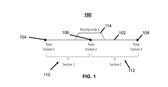
[0054] FIG. 1 shows a graphical representation of a portion of a rail
system 100. The
rail system 100 comprises a single-line rail 102, and three train stations
104, 106, 108 along
that rail line 102. Between the train stations 104, 106, 108 are a first
section 110 and a
second section 112 of the line 102. The rail system 100 also comprises a
passing loop 114.
A passing loop runs parallel to the rail line permitting two trains to pass
each other.
[0055] Sections of a rail line are delineated by the passing loops which
branch off of
the rail line. Each passing loop denotes a station, and each station denotes
the intersection
of two adjacent sections. The station (and the intersection of two sections)
is typically
considered to be the point on the main rail line that is parallel to the
midpoint of the passing
loop. The station (and intersecting point of two sections) may, however, be
anywhere along
- 8 -
CA 03030588 2019-01-11
WO 2018/027304 PCT/CA2017/050891
the main rail line between the ends of the passing loop. As shown in FIG. 1,
the midpoint of
passing loop 114 divides the first section 110 from the second section 112.
[0056] In the rail system 100, a train enters the first section 110,
stays within that
section 110 for a certain amount of time (e.g. the amount of time it takes for
the train to travel
the length of the section), and then exits the section 110 into the next
section 112. Once the
train has left the section 110, another train can enter the section 110. Two
trains are not
permitted to be in the same section of a single-line rail at the same time.
[0057] In single-line rails, trains can only cross (also referred to as
pass) each other if
there is a passing loop 114 that is sufficiently long to hold the full length
of the shortest train.
One or more trains can enter a passing loop up to the capacity of the passing
loop. The
trains remain in the passing loop for a period of time to permit other
train(s) to transit the
section(s) 110, 112 of the main rail line 102.
[0058] Process systems typically comprise operations that are performed
in an
industrial production setting to convert raw materials into value-added
components or
materials. Typical process systems receive or produce chemicals, gases,
agricultural
products, minerals, food, pharmaceuticals, advanced materials, or any
combination of the
foregoing. Certain aspects of a process system may be configured or tailored
to achieve a
particular result with that system. Process systems can be modeled in a
computer. The
model can be used to help determine, using the computer, the optimal
configuration of the
process system to achieve a particular goal. For example, the goal may be to
maximize the
output of the system or the revenue from such outputs, minimize the inputs
into the system
or the cost of such inputs, or maximize the income resulting from the use of
the system.
[0059] A model of a process system may be represented as a series of
equations
reflecting real-world constraints in the system. A goal may be expressed as an
objective
function. The objective function comprises decisions variables. At least some
of those
decision variables correspond to variables in constrains of the model of the
system. For
complex process systems, a computer may be used to determine the values of the
decision
variables which optimize the objective function while adhering to the
constraints
characterized by the model.
[0060] There are various methodologies to assist with modeling process
systems
such as State-Task Network, Resource-Task Network, and Unit-Operation-Port-
State
- 9 -
CA 03030588 2019-01-11
WO 2018/027304 PCT/CA2017/050891
Superstructure (UOPSS). The methodologies assist with determining the
equations to use to
represent a process system.
[0061] In the UOPSS methodology, decision-making process system blocks
are
classified according to their fill-hold-draw (FHD) logistic characteristics.
In a fill-hold-draw
block, there are three types of operations: filling a vessel with materials,
holding the materials
in the vessel, and expelling the materials from the vessel. Two FHD
characteristic
classifications are batch process units and pool units. In a batch process
unit, raw material is
loaded (all at once or in several stages). After a certain processing time
elapses, product is
removed. In a pool unit, indefinite amounts of materials can be added and/or
removed at
unspecified times, including at the same time.
[0062] The system and method of the present disclosure describe a
computer-
enabled process which employs a collection of formulas expressing mathematical
and logical
relationships to represent or model limitations of a real-world rail system in
a computer. The
model and associated formulas are based on the operation of process systems,
but are
adapted to the unique constrains of a rail system. The present disclosure
describes using the
significant processing power of a computer to help determine an optimal
configuration of an
aspect of a rail system to satisfy a particular goal, constrained according to
the model.
[0063] The method and system of the present disclosure provide a number
of
benefits over conventional train scheduling software. Modeling a rail system
with a computer
in accordance with process systems methodology is a marked departure from
conventional
train scheduling software which in some cases attempts to fully simulate the
rail system in
the computer. Despite their significant processing power, it is still not
possible for current
computers to simulate all possible rail system scenarios to achieve feasible
train schedules
based on conventional simulation algorithms. The system and method of the
present
disclosure is an improvement over conventional train scheduling software. The
present
disclosure provides a process which helps reduce the amount of processing a
computer is
required to perform to determine a sufficiently optimal rail system
configuration, such as a
train schedule. In other words, the present disclosure provides a more
efficient computer
process. In addition to determining a train schedule, the process of the
present disclosure
can be used to optimize other aspects of a rail system other than a train
schedule.
- 10-
CA 03030588 2019-01-11
WO 2018/027304 PCT/CA2017/050891
[0064] In accordance with an embodiment of the present disclosure, a rail
system is
modeled according to a process systems model in the memory of a computer. An
intermediate model of the rail system may be created in a memory of a computer
as objects
via an object-oriented computer language such as C++, Java, and Python.
Creating such an
intermediary model can help with both representing the model on a graphical
user interface
to facilitate human interaction, and automatically converting, using a
computer, to a final
model having mathematical and logical relationships which can be used in
optimization
operations.
[0065] To facilitate the creation of the intermediary model in the
memory, general
classes of the model objects (such as batch process units and pool units) may
be predefined.
The classes may have attributes and relationships in accordance with a
particular process
system model methodology. Objects may then be created in the memory based on
the
classes to represent the actual elements of a particular rail system.
[0066] The intermediate model is converted, using the computer, into a
final process
system model of the rail system in the memory. The final process system model
consists of a
series of equations expressing mathematical and logical relationships. The
equations define
real-world constraints and degrees of freedom in the rail system.
[0067] FIG. 2 shows a graphical representation of a model 200 of the rail
system 100
of FIG. 1 in accordance with an embodiment of the present disclosure. The
model 200 is in
accordance with a process system model. Rail line sections 110, 112 are
represented as
batch process units 202, 204. Passing loop 114 is similarly represented as a
pool unit 206. A
pool unit is used to represent the one or more trains that can be in a
corresponding passing
loop at any point in time. A particular type of train (based on its unique
combination of train
characteristics) passing through a rail line section or a passing loop may be
represented as a
state (also referred to as an operation mode) in the corresponding batch
process unit or pool
unit. A station yard which has capacity to accommodate one or more trains is,
effectively, a
passing loop. Accordingly, station yards may be represented as pool units in
the model.
[0068] In accordance with an embodiment of the present disclosure, batch
process
units and pool units may each have one or more operation modes associated
therewith.
Each operation mode represents a type of train which may traverse a particular
section or
passing loop. There is a train type for each unique combination of real-world
train
-11 -
CA 03030588 2019-01-11
WO 2018/027304 PCT/CA2017/050891
characteristics and/or track characteristics. Train characteristics can
include, for example,
train use type (e.g. passenger or freight), train length (which may be
associated with one or
more train use types), train weight (by axle or otherwise), train speed, train
load, train braking
system capacity, train direction, and train priority. These train
characteristics may be more
generally represented according to train size, speed, direction, and priority.
For example, one
train type may be a train with a long length that travels at a slow rate in a
first direction and
has a low priority. A second train type may be a train with a short length
that travels at a fast
rate in the first direction and has a low priority. Track characteristics can
include, for
example, availability and the number of parallel rails for a particular
section of track.
[0069] The number of operation modes may depend on the number of desired
train
characteristics to be considered. As shown in FIG. 2, a particular train
passing through a rail
line section 110 or passing loop 114 may be represented as one of the
operation modes 208,
210, 212, 214 in the batch process unit 202, and operation modes 224, 226,
228, 230 in the
pool unit 206. If the passing loop can hold more than one train at a time, an
inventory
constraint of the pool unit is set to the number of trains which can be
accommodated by the
pool unit at any one time. The single-use constraint of the pool unit (which
requires only one
operation mode to be active at any one time) is also removed.
[0070] A section or passing loop may have restrictions. The restrictions
may be
based on train characteristics and/or track characteristics. For example, a
single-track
section can only permit a train to proceed in one direction but not the
opposite direction at
the same time. A section or passing loop may also only be able to accommodate
trains of a
particular length but not all lengths.
[0071] The method and system of the present disclosure may generate a
discrete
time schedule. At certain times during that schedule, however, a portion of
the rail system
may not be available due to, for example, track maintenance. Accordingly, to
account for a
section of track that is not available during a period of time in the model,
the section's
availability (represented by setup variable ys,m,d,t in the model as further
discussed below)
may be set to a value of zero for the period of time. It may be necessary to
account for
unavailable tracks in the model when the actual track is, for example,
undergoing
maintenance. The method and system will find a feasible train schedule that
satisfies this
requirement if one exists.
- 12 -
CA 03030588 2019-01-11
WO 2018/027304 PCT/CA2017/050891
[0072] In an embodiment, the collection of operation modes associated
with a
particular batch process unit or pool unit represents the different trains
(based on the number
of unique combinations of train characteristics) which may be able to traverse
the
corresponding section / passing loop.
[0073] The model 200 in FIG 2. shows as many operation modes for each
train
section and passing loop as there are train types in each direction. More
specifically, a batch
process unit 202 comprises four operation modes 208, 210, 212, 214. The
operation modes
208 and 210 represent a first train type (Ti) travelling in a left direction
(D1) and a right
direction (D2), respectively. The operation modes 212 and 214 represent a
second train type
(T2) travelling in a left direction (D1) and a right direction (D2).
[0074] In the model 200, each operation mode in batch process unit 202
has a
connection to a corresponding operation mode in the other batch process unit
204 and the
pool unit 206. Notwithstanding, in accordance with the present disclosure,
there may be
different connectivity between rail sections and passing loops depending upon
the
characteristics of the trains those sections and passing loops can
accommodate. For
example, a short passing loop may be unable to accommodate a freight train
because of the
freight train's length. Such limitations may be represented in a model by
limiting connectivity
between the operation modes of each section and/or passing loop.
[0075] In an embodiment, the following formulas may be used to represent
mathematical and logical relationships of elements of the rail system in a
process systems
model. These formulas are based on the UOPPS methodology. In accordance with
an
embodiment of the present disclosure, the nomenclature used in the formulas is
as follows:
[0076] Sets: section (s), direction (d), large section (Is), mode/train
type (m), passing
loop (p1), and time (t).
[0077] Parameters: UTs,,,,d is the uptime of mode m in section s in
direction d.
[0078] Variables:
Ys,m,d,t is the setup of section s running train m in direction d in
time period t.
sus,m,d,t is the startup of section s running train m in direction d in
time period t.
sds,m,d,t is the shutdown of section s running train m in direction d in
time period t.
- 13-
CA 03030588 2019-01-11
WO 2018/027304 PCT/CA2017/050891
FPLipi,m,d,t is the flow of train m into passing loop pl in direction d in
time period t.
FPLopi,m,d,t is the flow of train m out of passing loop pl m in direction d
in time period t.
InvPLpi,m,d,t is the number (also referred to as inventory) of trains m in
passing loop pl
in direction d in time period t.
is the setup of large section Is running train m in direction d in time period
t.
Throughputm,d,s is the total number of trains of train type m that goes
through section s in
direction d.
[0079] A section of a rail system may be represented as a batch process
unit in a
process systems model of the rail system using the following two formulas:
T s d-1
Equation 1: Yu
¨tt=o' sus,m,d,(t-to = Ys,m,d,t V S,m,d,t I (t ¨ tt) 0
Equation 2: sdsdn,d,t = susdn,d,(t-uTs,,,,d+i) V s,m,d,t
I (t ¨ UTsdn,d + 1) 0
[0080] A passing loop of a rail system may be represented as a pool unit
in a process
systems mode of the rail system using the following formula:
Equation 3: InvPLpl,m,d,t = InvPLp1,m,d,t-1 + F PLipl,m,d,t F PLOpidn,d,t
Vpl,m,d,t
[0081] As discussed above, a sections or passing loop of a rail system may
only be
able to accommodate one type of train in one direction at a point in time.
This is referred to
as a single-use constraint.
[0082] A single use constraint for a passing loop may be represented in
the process
system model of the rail system using the following formula:
Equation 4: Ein Ed ITIVPLpon,d,t 1 Vpl, t
[0083] A single-use constraint for every section in every direction may be
represented using the following formula:
Equation 5: ysdn,d,t 1 V s , d, t
[0084] A single-use constraint for a single-line section may be
represented in the
process system model of the rail system using the following formula:
Equations 6: v
A_,G1 s,m,d,t 1 V t , S = single line section
- 14 -
CA 03030588 2019-01-11
WO 2018/027304 PCT/CA2017/050891
[0085] The following formulas are used to represent the constraints of
connections
between adjacent sections and a passing loop:
Equation 7: sdus,,,,,d,t FPLipi,,,,,d,t V s, pl, m, d, t
Equation 8: Sltds,no,t F PLOpon,d,t V s, pl, m, d, t
Equation 9: Sltds,no,t Sdus,m,d,t ¨ FPLiponAt FPLOpon,d,t V s, pl, m, d, t
Equation 10: Sltds,no,t FPLiponAt Sdus,m,d,t V s, pl, m, d, t
Equation 11: Sdusmdt + FPLopon,d,t 1 where "us" and "ds" correspond to
sections that are upstream and downstream, respectively, of passing loop pl.
[0086] Alternatively, if adjacent sections do not have a passing loop
therebetween
(e.g. when at least one of the adjacent sections is a multi-line rail), the
following formula is
used (instead of the formulas in Equations 7 to 11) to represent the
constraints of
connections between the adjacent sections:
Equation 12: Sltds,no,t ¨ Sdus,m,d,t = 0
[0087] A single-use constraint for a plurality of adjacent sections may
be represented
in the process system model of the rail system using the following formulas:
Equation 13: yLls,,,,d,t v >
¨ .,s,m,d,t V1S, S E Is, d,m, t
Equation 14: Ed yLis,m,d,t 1 V /s, m, t
[0088] FIG. 3 shows a graphical representation of a model 300, in
accordance with
another embodiment of the present disclosure, of another portion of a rail
system which is
similar to the portion of the rail system 100 of FIG. 1. The second portion,
however,
comprises a short passing loop and a long passing loop (instead of one passing
loop), and
three sections (instead of two sections). The short passing loop and long
passing loop are
represented as a first pool unit 308 and a second pool unit 310, respectively.
The three
sections are represented by batch process units 302, 304, 306. The short
passing loop can
only accommodate trains of a first type (that are short). The long passing
loop can
accommodate both the trains of a first type (that are short) and trains of a
second type (that
are long). To represent the limitations of the short passing loop in the model
300, only two
operation modes 328, 330 are associated with the first pool unit 308. In other
words, the first
pool unit 308 can never be in an operation mode other than the operation modes
- 15-
CA 03030588 2019-01-11
WO 2018/027304 PCT/CA2017/050891
corresponding to the short train type. By contrast, the second pool unit 310
comprises all four
operation modes, namely, two directions (D1, D2) for each of the two train
types (Ti, T2).
[0089] The connections between the operation modes also reflect the real-
world
limitations with respect to the short passing loop. Operation modes Ti Di and
Ti D2 in each
of batch process units 302, 304 have connections to operation modes Ti Di and
Ti D2 in the
first pool unit 308. Operation modes T2D1 and T2D2 in the batch process units
302, 304,
however, have no corresponding connections to the first pool unit 308.
[0090] Train travel times (runtimes) through the rail system may not only
be different
between train types, but may also be different between the same train type
operating in
opposite directions. This may be due to the existence of hills across the rail
system, train
load, type of train braking system, and train configuration (e.g. number and
type of
locomotives, number and type of wagons/cars).
[0091] In an embodiment of the present disclosure, additional operation
modes may
be associated with a batch process unit or pool unit to model a same train
type having
different travel times depending on the travel direction. By explicitly
modeling each train type
with a particular direction, different runtimes can be assigned.
[0092] Single-track rails (also referred to as single-line rails) may
coexist with double-
track or multi-track rails (also referred to as double-line or multi-line
rails). Single-track rails
cannot accommodate two trains travelling in the same section at the same time.
By contrast,
multi-track rails permit trains to simultaneously travel in the same section
at the same time,
so long as there is no more than one train on each track of the section.
Limited flexibility
systems may contain both single-track rails and multi-track rails. In
accordance with an
embodiment of the present disclosure, a multi-track rail section may be
represented in a
process systems model as a single batch process unit comprising an additional
variable
representing the number of trains that can traverse the track at the same
time.
[0093] FIG. 4 shows a representation 400, 402 for each of a single-track
section, and
a double-track section, respectively. For the single-track section
representation 400, all four
operation modes 408, 410, 412, 414 (two train types for each of two
directions) are
represented in the single-use constraint. For the double-track section
representation 402,
however, there are two independent single-use constraints 404, 406: one for
each direction.
Based on the double-track section representation 402, it follows that only one
train type can
- 16 -
CA 03030588 2019-01-11
WO 2018/027304 PCT/CA2017/050891
be traveling in a particular direction in the section in a time period, but
that the same train
type or different train types may be travelling in an opposite direction in
the section for the
same time period. A station (and the intersection of two adjacent sections) is
located at the
point a single-track rail turns into a multi-track rail. The full length of a
multi-track rail may be
one entire section. A multi-track rail may be subdivided into multiple smaller
sections. The
distance between each of the smaller sections permits sufficient headway
between trains
traveling in those sections so trains can follow one another. The connection
between two
adjacent sections of a subdivided multi-track rail may be modeled using
Equation 12
Sdus,m,d,t = =
[0094] FIG. 5 shows a representation 500 of two trains moving in the same
direction
on the same rail, and a representation 550 of two trains approaching each
other from the
opposite directions on the same rail. Each representation 500, 550 shows
sections and three
passing loops, namely, two longer passing loops and a shorter passing loop.
Trains (whether
long or short) may follow each other from section to section when traveling in
the same
direction. When trains approach each other from opposite directions, however,
one of the
trains must pull into the passing loop and wait for the other oncoming
train(s) to completely
clear all sections up until the passing loop before emerging. Where the trains
are long trains
as shown in representation 550, and the sections between the trains connect to
a short
passing loop 552 (that is unable to accommodate either train) and a long
passing loop 554
(able to accommodate a train), one of the trains must wait in the long passing
loop 554 for
the other train to clear all sections 556, 558, 560 between the two passing
loops 552, 554. In
other words, the presence of a long train in a section 556 precludes a series
of adjacent
sections 558, 560 from being occupied by another long train if it is
approaching from an
opposite direction. Such real-world constraint may need to be incorporated
into a model in
accordance with the present disclosure. Dividing a rail into sections
according to the
locations of longer passing loops, only, for the purpose of creating the model
may result in
overly conservative solutions. This is because the model would represent two
or more single-
track sections as one longer section. Even though a train could occupy each of
the sections,
since the model treats the multiple sections as only one longer section, the
train schedule
would not have multiple trains in the one longer section at the same time.
[0095] In an embodiment of the present disclosure, a variable may be
associated
with a series of batch process units between two or more passing loops, when
only one of
- 17-
CA 03030588 2019-01-11
WO 2018/027304 PCT/CA2017/050891
those passing loops can accommodate a long train. The variable may be referred
to as a
large section variable. When representing a long train passing through one of
the series of
batch process units, the large section variable is enabled (binary value of
"1") for all of the
other batch process units. This places a constraint on the model that
inhibits, during
optimization, any of the sections from being used by another long train when a
long train is
already in one of those sections. In other words, it forces another
approaching long train to
wait in the long passing loop while the first long train clears the series of
batch process units.
A single use constraint on this new binary variable helps ensure the
representation of only
one of these sections being active when trains are traveling towards each
other in opposing
directions, but also helps ensure the representation of all of these sections
being active when
trains are following each other in the same direction, as shown in Equations
13 and 14.
[0096] FIG. 6 shows a graphical representation of a model 600, in
accordance with
an embodiment of the present disclosure, of a third portion of a rail system.
The third portion
is larger and more complex than the portions of rail systems modeled in FIG. 2
and FIG 3. As
can be extrapolated from the graphical representation of the model 600, the
portion of the
third rail system comprises 12 sections (sections 0 to 11). Each section can
accommodate
two types of trains (e.g. a short train type and a long train type) in either
direction. Section 0
to 3 is each a single-track rail. Section 4 is a double-track rail that is
able to accommodate
two trains at the same time. Section 5 to 11 is each a single-track rail.
There are 9 passing
loops (0 to 8). Passing loops 0 connects to sections 0 and 1 but can only
accommodate one
type of train (e.g. a short train type) in either direction. Passing loop 1
connects to sections 1
and 2 and can accommodate both types of trains in either direction. Passing
loop 3 connects
to sections 5 and 6 and can also accommodate both types of trains in either
direction.
Passing loops 4, 5, 6, and 7 connects to section pairs 6-7, 7-8, 8-9, and 9-
10, respectively
but can only accommodate one type of train (e.g. the short train) in either
direction. Lastly,
passing loop 8 connects to sections 10 and 11 and can accommodate both types
of trains in
either direction.
[0097] As show in the visual representation of the model 600, in
accordance with an
embodiment of this disclosure, each of the sections is represented as a batch
process unit
602. Each batch process unit 602 comprises four operation modes 604, 606, 608,
610
representing each of the two types of trains for each direction. Each of the
passing loops is
- 18-
CA 03030588 2019-01-11
WO 2018/027304 PCT/CA2017/050891
represented as a pool unit 612. Connectors 614 help model which passing loops
can
accommodate which types of trains.
[0098] Since passing loop 1 can accommodate long train types, but passing
loops 0
and 2 cannot, the operation modes representing right-travelling trains for
sections 0-1 616,
and sections 2-3 618 are each modeled with an additional variable (also
referred to as an
adjacency constraint). The additional variable yL in Equations 13 and 14 help
ensure that
when two long trains are approaching each other from opposite directions, both
sections are
unavailable if any one of the sections is occupied by one of the trains.
Similarly, the operation
modes representing right-traveling trains for sections 6, 7, 8, 9, and 10 620
are also modeled
with the additional variable since only passing loops 3 and 8 can accommodate
long trains.
[0099] FIG. 7 shows a flow chart of a method 700 for modeling a rail
system based
on a process system model. The method 700 comprises representing, in a memory
of a
computer, sections as batch process unit 702, representing passing loops as
pool units 704,
representing train types of trains that may traverse each batch process unit
or pool unit as
operation modes 706, and representing connections between sections, and from
sections to
passing loops, as relationships between operation modes 708. The process
systems model
of the rail system does not need to strictly conform to all aspects of process
systems
modelling methodology. Rather, the process systems modelling methodology
provides a
framework to assist with modeling the elements of a rail system as if they
were elements in a
process system. Differences between train networks and process systems,
however, still
need to be reflected in the model of the rail system. These differences are
reflected by
adding additional constraints to the model, or relaxing certain in the model.
Such model
differences may not conform to the conventions of a process system modeling
methodology.
[00100] Once a rail system has been modeled in accordance with a process
system
model, the model may be used to help determine an optimal configuration of
various aspects
of the rail system. For example, the model may be used to help determine a
train schedule or
identify infrastructure changes to the rail system to improve train
throughput. The use of the
model depends, in part, upon the goal/objective to be achieved. There may be
many types of
objectives that are of interest with respect to a rail system.
[00101] FIG. 8 shows a flow chart of a method 800 for determining, using a
computer,
a configuration of a rail system for optimizing an aspect of that rail system.
The method 800
- 19-
CA 03030588 2019-01-11
WO 2018/027304 PCT/CA2017/050891
comprises creating a process systems model 802 of the rail system in a
computer memory;
creating an objective function 804 in the computer memory, the objective
function
corresponding to the aspect of the rail system to be optimized; and
determining a
configuration of the rail system 806, using the computer, which optimizes the
objective
function in accordance with constraints in the model. The system for this
method may
comprise a computer, and a memory storing a program configured, using the
computer,
create the process systems model in the memory, create the objective function
in the
memory, and optimize the objective function. The memory may store an
optimization solver
program to assist with optimizing the objective function.
[00102] In an embodiment, the method comprises determining a train
schedule which
optimizes an aspect of the rail system. For example, the train schedule may be
to maximize
the percentage of time sections of the rail system are occupied by trains. In
another
embodiment, the train schedule may be to minimize the number of times passing
loops are
used by trains. In an embodiment, the model comprises or is provided with a
list of trains,
each train's departure location and destination in the rail system, and the
time at which each
train is to reach its destination. In another embodiment, the model comprises
or is provided
with the minimum and/or maximum total number of trains of a certain type that
must traverse
the system within a particular time horizon. Trains may be weighted
differently in the model
such that the arrival and/or departure of certain trains' results in a greater
number of points
being awarded than the arrival and/or departure of other trains. The points
may correspond
to financial incentives such as costs or revenues.
[00103] The first step of the method 800 is to create a process systems
model 802 of
the rail system in a memory of a computer. The units of the model represent
real-world
elements in the rail system such as track sections and passing loops. The
model of the rail
system is created base on methodology/framework used to model a process
system, such as
the UOPSS framework. It is essential for the model to be created in a computer
memory
since any optimization operation performed with the model (such as determining
a train
schedule) requires the use of a computer. The model of a rail system is
complex. As further
described below, only a computer is capable of determining a solution to the
optimization
problems resulting from the complex model of the rail system.
[00104] The second step of the method 800 is to create an objective
function 804 in
the memory of the computer. The objective function is a mathematical
expression or function
- 20 -
CA 03030588 2019-01-11
WO 2018/027304 PCT/CA2017/050891
representing a particular goal to be achieved by the rail system. The
objective function
comprises decision variables expressed as a linear relationship. The decision
variables
represent real-world relationships and/or factors which need to be considered
and/or
configured. The decision variables are used to assess whether a particular
configuration of
the rail system is better or worse than another. Optimization comprises
identifying the values
of the decisions variables which maximizes or minimizing (depending on the
goal) the
objective function but which also adhere to the constraints imposed on the
decisions
variables as a result of the equations in the model. This is referred to
herein as optimizing the
objective function for, or in accordance with the constraints in, the model.
[00105] The following are examples of the types of objective functions for
optimizing
an aspect of the rail system: determining a feasible train schedule for the
rail system for a
particular time horizon (e.g. seven days); determining a train schedule which
minimizes the
usage of passing loops by all trains; determining a train schedule which
maximizes the
utilization of all sections in the rail system; determining a train schedule
which minimizes the
amount of time it takes for trains of a particular type to travel to its
destination.
[00106] Decision variables typically represent the degrees of freedom in a
system.
Decision variables have coefficients which indicate how much a decision
variable contributes
to the value of the objective function. What decision variables are included
in the objective
function depends on the objective, namely, the value to be optimized.
[00107] If the goal is to minimize use of passing loops by trains, the
objective function
may comprise decision variables representing the number of pool units used by
the trains.
The coefficients for those decision variables may reflect a real-world penalty
value (e.g.
monetary cost) associated with the use of a pool unit. Multiple decision
variables (instead of
a single variable) may be used in the objective function to more precisely
represent real-
world considerations when trains use passing loops. For example, a higher
penalty value
may need to be reflected in the objective function when a train with a higher
priority uses a
passing loop. In other words, the objective function may comprise a decision
variable
corresponding to a passing loop penalty for each train type in a rail system.
In another
example, a lower penalty value may need to be reflected in the objective
function when
passing loops which are closer to a port (such as a station) are used. This is
because
passing loop usage closer to a port (or at a crew changeover train station)
may be more
acceptable (and therefore attributed a lower penalty value) than usage of
passing loops (and
- 21 -
CA 03030588 2019-01-11
WO 2018/027304 PCT/CA2017/050891
associated delays) at other locations. The objective function may comprise
decision variables
for different passing loop penalties based on spatial prioritization for the
usage of passing
loops.
[00108] The following is an example objective function representing the
minimization
of the time all train types m spend in all passing loops pl, in all directions
d over the entire
decision-making time horizon NT which is represented by the summation of all
inventory
amounts InviAt (weighted by their respective penalty values Wm):
NT NPL NM ND
mm Wpc1. 171.11pomd,t
t=1 p1=1 m=1 d=1
[00109] The third step of the method 800 is to determine a configuration
of the rail
system 806, using a computer, which optimizes the objective function according
to the
model. Optimizing the objective function according to the model means that the
collection of
decision variables which optimizes the objective function also satisfies all
of the constraints
of the equations underlying the model.
[00110] If the goal is to determine a train schedule, the third step of
the method 800 is
to determine, using a computer, a train schedule 806 which optimizes the
objective function
according to the model. A train schedule may comprise the departure and
arrival time of
each train at one or more locations in a rail system. Alternatively, a train
schedule may
comprise periods of time when each train is at a particular location in the
rails system. A
location may be a section of the rail system, a passing loop, or a station.
The locations may
be all of the sections of the rail system or all of the stations.
[00111] In an embodiment, the computer uses an optimization solver program
to
determine the values of the decision variables which optimize the objective
function while
adhering to the constraints in the model. Optimization solver programs are
commercially
available. IBM ILOG CPLEXTM optimizer is an example of a commercially
available
optimization solver program. The model and objective function may be provided
to an
optimization solver program through an application programming interface. The
optimization
solver program may return the values of the decisions variables as objects.
Generally, the
optimization solver program identifies the values of the decisions variables
which optimize
the objective function using various search strategies. Using the search
strategies, the
- 22 -
CA 03030588 2019-01-11
WO 2018/027304 PCT/CA2017/050891
optimization solver program effectively considers many of the possible
configurations of the
rail system over a specified period of time. The search strategies are
constrained by the
search space based defined by the model.
[00112] Optimization consists of either maximizing or minimizing the value
of the
objective function, depending on the corresponding goal to be achieved with
the rail system.
An objective function may be optimized within a specified optimality tolerance
to reduce the
amount of time it takes to arrive at the solution. Determining a solution
using an optimality
tolerance may not result in the most optimal solution. That solution may still
be sufficiently
optimal, however, for the intended purpose with the benefit being that it took
less time (and
sometimes significantly less time) to compute the solution. By relaxing the
model of the rail
system, an upper bound maximum or lower bound minimum of the objective
function can be
determined for the purpose of assessing the optimality of a solution. For
clarity, relaxation
does not identify the values of the decisions variables of the objective
function which results
in optimization, it simply helps provide an upper or lower bound.
[00113] A computer is an essential element of the method and system of the
present
disclosure. A computer is required to optimize an objective function in
accordance with a
process systems model of a rail system. Because of the complexity of a rail
system, a human
operator would be unable to solve such an optimization problem manually (i.e.
without a
computer), and certainty not within a period of time that would allow the
solution to be useful.
As shown below in relation to Table 1, determining a train schedule for just a
2-day time
horizon can result in 382,474 decisions variables and a model resulting in
470,994
equations. A solution to that large number of equations and decisions
variables would be
impossible to compute unless a computer is used. Even if it were possible to
determine a
solution manually, it would take an exceeding long time to do so. A rail
network is a dynamic
environment. Train schedules, for example, need to be generated within a
reasonable
amount of time from the point at which a model of the actual environment is
created. What is
a reasonable amount of time depends, in part, on the purpose of the train
schedule. For
online applications, a train schedule would need to be generated within a few
minutes. For
offline planning purposes, a train schedule would preferably be generated
within 30 minutes.
It may indeed be acceptable for a train schedule to be generated within a
period of hours. It
is unlikely that a train schedule would be of much use for operational
purposes if it took
multiple days to generate. If it takes too long to create a train schedule,
the actual rail
- 23 -
CA 03030588 2019-01-11
WO 2018/027304 PCT/CA2017/050891
network will have sufficiently changed such that the model is out of date. A
train schedule
resulting from an out of date model cannot be used for the purpose of
scheduling trains.
Furthermore, it would be infeasible to suspend all activity on the rail
network while a solution
is being determined without a computer. Suspending all trains on a rail
network for even a
short period could result in significant economic losses.
[00114] Once a train schedule has been determined, the trains in the rail
system may
be operated in accordance with the train schedule. Depending on the system,
the trains may
be automated so that they automatically operate in accordance with the train
schedule. The
trains may be dispatched from their starting locations according to the train
schedule. The
signals which are used to control the flow of trains through the rail system
may be operated
in accordance with the train schedule.
[00115] The speed of trains may also be regulated for each of the sections
so that the
train adheres to the train schedule. Indeed, slower, constant, train speeds
may result in a
more optimized rail system if the slower speeds results in less or no
conflicts. A train requires
significant energy and time to change velocity. The heavier the train, the
more time and
energy required. Accordingly, changes in train velocity are preferably
avoided. If a particular
train schedule guarantees no conflicts and therefore no scheduled changes in
train velocity,
it may be preferable to adhere strictly to that schedule notwithstanding that
certain trains may
be able to travel faster in certain sections.
[00116] The following describes different purposes for which the system
and method
of the present disclosure may be used. The purpose determines the objective
function, and
the decision variables of the objective function identify what aspects of the
rail system may
be configured to achieve the purpose.
[00117] In an embodiment, the system and method may be used to obtain a
feasible
train schedule given a particular train launch timetable.
[00118] In an embodiment, the system and method may be used to identify a
train
schedule which minimizes the usage of passing loops for all train types given
a pre-specified
train launch schedule where train dispatch times are specified at the battery
limits to the
problem. In other words, the model comprises or is provided with the departure
location of
each train, and the window of time within which each train is required to
depart. The solution
- 24 -
CA 03030588 2019-01-11
WO 2018/027304 PCT/CA2017/050891
to this objective may be a sufficient but indirect proxy for a schedule that
minimizes the
runtime of trains through a rail system.
[00119] In another embodiment, the system and method may be used determine
a
train schedule that maximizes the number of trains running through the system.
This can
help determine the rail system's maximum capacity and/or identify bottleneck
sections. The
objective function of this objective may be expressed as the maximization of
all of the train
flows leaving the system in both directions, for all train types. The model
may comprise
constrains to inhibit the optimizer from attempting solutions which only send
the shortest
trains through the rail system.
[00120] In another embodiment, the system and method may be used to
determine a
revised train schedule for recovering from an unforeseen event, such as a
locomotive
breakdown. In this case, the model of the rail system is adjusted to reflect
the rail system
after the event, and a revised train schedule is determined using the adjusted
model so as to
re-established traffic as quickly as possible. The revised train schedule may
be optimized to
reestablish, as quickly as possible, operation of the rail system according to
the original train
schedule prior to the event. This is a challenging task for conventional train
scheduling
simulation software since the rules and heuristics used by such software are
based on
launching trains from stations at the extremes of the rail line, as opposed to
stations within
the rail system. In an embodiment, the process systems model of the rail
system is populated
to reflect start of schedule conditions such as train locations. This may be
accomplished by
setting the values of setup binary variables to the value of "1" at start-of-
schedule in the
sections in which trains are staged. This is also referred to as setting a
baseline in a process
systems model.
[00121] It can be difficult for rail operators to determine the maximum
capacity of their
rail systems. Operators may rely on historical train schedules and/or
hypothetical estimates
of maximum capacity. In an embodiment, the method and system may be used to
determine
the maximum useful rail system capacity, which may then be maximized for the
existing track
infrastructure.
[00122] The flexibility in the scheduling of trains in a rail system may
be greater when
the rail system comprises many long passing loops and a large yard capacity at
every
station. Such flexibility, however, is at the potential expense of inflated
capital requirements
- 25 -
CA 03030588 2019-01-11
WO 2018/027304 PCT/CA2017/050891
to construct the passing loops and yard capacity. Scheduling efforts are also
typically
simplified in dedicated (single purpose, same train priority, homogenous train
and passing
loop design) rail lines. In systems with limited passing loop infrastructure
and mixed (e.g.
freight/passenger) utilization, however, more sophisticated models,
algorithms, and
computation may be required.
[00123] Limited-flexibility rail systems are often the results of multiple
expansions or
upgrades that are implemented over a period of time (years or decades). Such
rail systems
make it challenging to manually schedule trains. Such rail systems also make
it difficult or
impossible for discrete event simulation tools, rule-based scheduling tools,
and heuristic-
based scheduling tools to determine a conflict-fee train schedule for a
particular time horizon.
This is because such tools are unable to account for all of the complexities
of the rail system
when attempting to determine a rain schedule. Attempted use of such tools for
limited-
flexibility rail systems may result in lower utilization of rail system
capacity than what is
actually available. Attempted use of such tools for limited-flexibility rail
systems may also
result in very slow recovery from unforeseen disruptions to the operation of
the rail system,
such as locomotive breakdowns. Indeed, some conventional tools are unable to
schedule
trains in a rail system that already contains trains at certain locations in
the system because
of the added complexity. Given the capital intensity typically required to
expand on existing
rail infrastructure, there is also significant interest in methods and systems
which can
optimize the use of existing rail systems, and/or identify the best track
expansion locations to
improve efficiency.
[00124] In an embodiment, the method and system may be used to assess the
optimal
phasing of expansion of rail infrastructure by either extending existing
passing loops, or
adding new ones to the system. This can be achieved by adding a binary
variable to the
model that corresponds to the usage of each passing loop expansion option, and
penalizing
any use with its corresponding capital expenditure amount in the objective
function.
Therefore, given the values assigned to each completed train trip, the
optimization will only
use the extra expansion if the increased capacity benefit outweighs its
required capital
expenditure.
[00125] In another embodiment, the system and method are integrated with a
train
control system of a rail system. The train control system may automatically
provide the
system and method with real-time or near real-time information regarding
elements and/or
- 26 -
CA 03030588 2019-01-11
WO 2018/027304 PCT/CA2017/050891
events in the rail system. For example, information about an event may be
received within
less than 5 minutes after the time at which the event occurred. The
information may be
provided continuously or periodically. The information may include the
location, speed, and
direction of trains in the rail system. The information may also include train
conflicts, train
malfunctions, section availability, and scheduled track maintenance. Using
this information,
the system and method may be provide a real-time or near real-time train
schedules.
[00126] In another embodiment, the system and/or method operates in real-
time,
receiving batch or continuous updates concerning the state of the rail system
for the system
and method to provide rapid, short-term optimization of the rail system,
including when there
is an upset to, or an unexpected event in, the rail system.
[00127] FIG. 9 shows a Gantt chart 900 of a 1-week train schedule for a
large-scale,
real-world, rail system determined according to an embodiment of the system
and method of
the present disclosure. The rail system comprised 21 sections, 16 passing
loops, and 5
different train types. The rail system was a mixed-use rail corridor of 370
kilometers.
Conventional train scheduling software was unable to find a feasible train
schedule for this
rail system greater than a 2-day time horizon.
[00128] The vertical axis of the chart 900 represents each rail section in
the rail
system. The horizontal axis of the chart 900 represents discrete time periods
in 10 minute
increments (although another value could have been selected such as 1 minute
increments
or 1 hour increments). Rows 902, 904, 906, and 908 represent double rail
sections which
may simultaneously accommodate trains traveling in both directions. Each block
910
represents a particular train at a particular section for a particular time
period. The colour of
the block represents the train type.
[00129] In the model of the rail system, a time step of 10 minutes was
used. This was
because of the short travel times between stations. In the model, all train
runtimes were also
rounded up to the nearest 10 minute increment to achieve a more conservative
solution.
[00130] An objective function was created to minimize the usage of passing
loops for
all train types given a pre-specified train launch schedule.
[00131] The method and system was implemented using the C++ programming
language. Commercial optimization software IBM ILOG CPLEXTM was used to
optimize the
- 27 -
CA 03030588 2019-01-11
WO 2018/027304 PCT/CA2017/050891
objective function. The software ran on a laptop computer with an 8-core Intel
Core 2.40 GHz
processor and 8GB of RAM. The optimality tolerance for all cases was set to
5%.
[00132] In a first case, the method and system were used to determine a 2-
day train
schedule. For this first case, the decision variables of the model comprised
both continuous
variables and integer variables. This resulted in a large scale mixed-integer
linear program
(MILP). A continuous variable can be any floating point number that is
positive or negative.
An integer variable can only be a positive, zero, or negative whole number.
Details
concerning the model statistics for this case are set out in Table 1, below.
The details
comprise the number of decision variables in the model, including the number
of integer
decision variables and continuous decision variables both for the original
problem statement
as well as the number of presolved variables after IBM I LOG CPLEXTM
presolving operations.
The details also comprise the number of equations and the number of non-zero
elements.
[00133] In the first case, the time required to determine the first
integer-feasible
solution was approximately one minute. The time required to determine an
optimal feasible
solution (i.e. within 5% of the most optimal solution) was approximately 20
minutes. Details
concerning the solution performance statistics for this case are set out in
Table 2, below.
[00134] In a second case, the decision variables of the model were made to
comprise
only integer decision variables. More specifically, all dependent continuous
decisions
variables were explicitly declared as integer such that the model became a
pure integer
programming (IP) model. This resulted in more binary variables in the model.
Table 1
provides the model statistics for this case. Significant improvements were
observed in the
time required to find an optimal solution with this model as compared to the
model in the first
case. In fact, the most optimal solution (i.e. within 0.0% of the most optimal
solution, also
known as a provably optimal solution) was determined within 58 seconds ¨ an 18-
fold
improvement in solve time as compared to solving the MI LP model of the first
case. Table 2
provides the solution performance statistics for this second case. The
improved results are
believed to be due, in part, to the cascading solution characteristics
inherent to rail
scheduling systems.
[00135] In a third case, the IP model of the rail system was used to
determine a 7-day
train schedule. Conventional train scheduling software is unable to determine
a feasible train
schedule, let alone an optimal train schedule, for a 7-day period. The third
case resulted in a
- 28 -
CA 03030588 2019-01-11
WO 2018/027304 PCT/CA2017/050891
model with over 1.3 million binary variables, 1.6 million equations and over 4
million nonzero
elements. This solution to the objective function was determined within less
than 20 min.
Table 1 provides the model statistics for this third case, and Table 2
provides the solution
statistics for this third case.
Case #Variables #Equations #Non-Zeros
2 Days 382,474 470,994 1,265,737
(MILP) (11,262 integer (63,843) (214,660)
variables,
26,969 continuous
variables)
2 Days 382,474 470,994 1,265,737
(IP) (38,328 integer (63,810) (215,328)
variables)
7 Days 1,338,634 1,627,314 4,412,857
(IP) (235,165 binary (380,726) (1,316,240)
variables)
Table 1: Model Statistics (Pre-solved values in parentheses)
Case let Feasible Optimal Optimality
Solution Solution Gap of
(CPU second) (CPU seconds) Solution
(oh)
2 Days 74* 1,080 5.0
(MILP) (Node 20,072)
2 Days 48* 58* 0.0
(IP)
7 Days 1,132* 1,132* 0.0
(IP)
* Solution obtained within CPLEX heuristics, prior to branch-and-bound
Table 2: Solution Performance
- 29 -