Note: Descriptions are shown in the official language in which they were submitted.
CA 03030620 2019-01-11
- 1 -
DESCRIPTION
"Gas cooking appliance"
TECHNICAL FIELD
The present invention relates to gas cooking appliances.
PRIOR ART
Gas cooking appliances are known, particularly gas cooking appliances,
comprising a
gas conduit feeding at least one gas burner with gas, and a gas valve, which
can be
a manually-operated gas cock, for each gas burner, which allows regulating gas
flow
towards the burner. The flame in the gas burner, particularly in gas
barbecues, is
usually ignited by acting on an ignition electrode by means of a push button
once the
passage of gas to the burner is opened.
US20150150404A1 describes a gas cooking appliance, particularly a gas
barbecue,
comprising a plurality of gas burners, an ignition electrode, a push button
for activating
the electrode, a gas valve for each burner for regulating gas flow reaching
the
respective burner from a gas conduit, an electromagnetic shut-off valve
arranged in
the gas conduit, a control unit for controlling the shut-off valve and a
control knob. To
turn on the gas cooking appliance and activate the control unit, the user must
open
the gas valve corresponding to the burner to be turned on, he must open the
shut-off
valve placing the control knob in a first angular position, then he must press
the push
button to activate the electrode, and finally place the control knob in a
second angular
position for activating the control unit.
DISCLOSURE OF THE INVENTION
The object of the invention is to provide a gas cooking appliance, as defined
in the
claims.
CA 03030620 2019-01-11
- 2 -
The gas cooking appliance of the invention comprises at least one gas burner,
an
ignition electrode for turning on the burner, a push button unit with a push
button for
activating the electrode, a gas valve for each burner for regulating gas flow
reaching
the respective burner from a gas conduit, an electromagnetic shut-off valve
arranged
in the gas conduit comprising a closure member for closing the passage of gas,
and a
control unit for controlling the shut-off valve.
The closure member of the shut-off valve of the gas cooking appliance of the
invention
comprises a stable closed position and a stable open position, said closure
member
going from the open position to the closed position and vice versa when the
shut-off
valve receives electromagnetic electric current pulses. In the context of the
invention,
a stable position is understood as that position in which the closure member
remains
fixed without having to electrically power the shut-off valve.
The push button unit of the gas cooking appliance of the invention is
configured for
performing three different functions when the push button is pressed with the
gas
cooking appliance off:
i) for pushing the closure member of the shut-off valve to the open
position,
ii) for activating the control unit, and
iii) for activating the electrode.
The push button unit can activate the electrode either directly or by means of
the
control unit. Once the push button has been pressed, the control unit controls
the shut-
off valve by means of electric current pulses.
Therefore, the gas cooking appliance of the invention incorporates a push
button unit
integrating in one single pressing operation at least the three cited
functions, giving
rise to an easier-to-operate and more compact gas cooking appliance with a
lower
cost due to the smaller number of parts forming it. The gas cooking appliance
of the
invention is simple and intuitive for the user, as he only has to open the gas
valve by
means of which the flow of gas to the burner is regulated and then press the
push
button. In particular the user of gas barbecues has internalized that he must
press a
push button for igniting the burner, but in the gas barbecues of the prior art
incorporating a shut-off valve and a control unit he need to perform further
operations
CA 03030620 2019-01-11
- 3 -
with actuators other than the push button unit to put the gas barbecue on.
These and other advantages and features of the invention will become evident
in view
of the drawings and the detailed description of the invention.
DESCRIPTION OF THE DRAWINGS
Figure 1 shows a perspective view of an embodiment of a gas cooking appliance
according to the invention, which in this case corresponds with a gas
barbecue.
Figure 2 shows a section view of an embodiment of the shut-off valve and the
push
button unit of the gas cooking appliance of the invention, and a schematic
representation of the control unit with which said shut-off valve and said
push button
unit interact.
Figure 3 shows a schematic view of the gas cooking appliance of Figure 1.
Figure 4 shows a schematic view of a second embodiment of the gas cooking
appliance of the invention.
Figure 5 shows a schematic view of a third embodiment of the gas cooking
appliance
of the invention.
DETAILED DISCLOSURE OF THE INVENTION
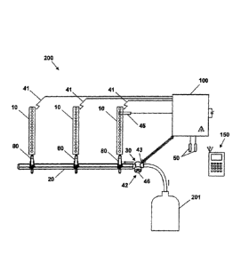
Figure 1 shows a perspective view of an embodiment of a gas cooking appliance
200
according to the invention, which in this case corresponds with a gas
barbecue, but
which in other embodiments (not depicted in the drawings) may correspond with
other
type of gas cooking appliances, such as gas ovens or gas cooktops, for
example. The
gas cooking appliance 200 comprises a support structure supporting a cooking
area
in the upper portion, the structure comprising a control panel in its front
portion. Inside
the structure, the gas cooking appliance 200 comprises in the upper central
portion a
cooking chamber in which there is a cooking surface 40, which is a grill in
this
- 4 -
embodiment, but which can be, for example, a griddle in other embodiments of
the
barbecue. In this embodiment, three gas burners 10 are arranged under the
cooking
surface 40. Each gas burner 10 has a respective associated manually-operated
gas
valve 80 for regulating gas flow reaching each burner 10 from a gas conduit 20
which
is connected to an external gas supply 201. Each gas valve 80 is actuated by
means
of a respective knob 81. As shown in Figure 3, in this embodiment, the gas
cooking
appliance 200 comprises, associated with each burner 10, an ignition electrode
41
which allows igniting the flame in each burner 10.
The gas cooking appliance 200 of the invention comprises an electromagnetic
shut-
off valve 30 arranged in the gas conduit 20, a push button unit 42 with a push
button
46, and a control unit (100) for controlling the shut-off valve (30). Figure 2
shows an
embodiment of the shut-off valve 30 and a schematic representation of the
control unit
100. The shut-off valve 30 comprises a closure member 33 for closing the
passage of
gas and is a bistable valve, the closure member 33 therefore comprising a
stable
closed position and a stable open position, said closure member 33 changing
its
position when receiving electric current pulses. The magnetic means of the
shut-off
valve 30 comprise a static armature 35, a static permanent magnet 37, and a
bobbin
36 that is placed in the static armature 35 and cooperates with the permanent
magnet
37 depending on its power supply, the closure member 33 moving when the bobbin
36 is powered by means of electric pulses. The closure member 33 also
comprises at
least one ferromagnetic part, the permanent magnet 37 attracting the
ferromagnetic
part when the closure member 33 is in the closed position. Logically, other
embodiments of the magnetic means are also possible, as long as two stable
positions
are established for the closure member 33 and it goes from one position to
another by
applying electric pulses to the magnetic means. Thus, in another embodiment,
the
shut-off valve 30 of the invention can be, for example, as the bistable valve
described
in W02014191349A1.
The push button unit 42 of the gas cooking appliance 200 is configured for, in
any of
its embodiments, perform at least three functions when the push button 46 is
pressed
with the gas cooking appliance 200 off:
i) push the closure member of the shut-off valve 30 to the open position,
Date Recue/Date Received 2022-06-08
. . CA 03030620 2019-01-11
. .
- 5 -
ii) activate the control unit 100, and
iii) activate the electrode 41.
Once the push button 46 has been pressed, the control unit 100 controls the
shut-off
valve 30 by means of electric current pulses. Therefore, by means of a single
pressing
operation by the user at least the three cited functions are performed.
In a first embodiment, shown in Figure 3, the gas cooking appliance 200
comprises an
electrical switch 43 which is activated when the push button 46 is pressed,
the
electrical switch 43 being electrically connected to the control unit 100.
When the
electrical switch 43 is activated the control unit 100 is activated and the
control unit
100 generates sparks in the electrode 41. The control unit 100 controls the
shut-off
valve 30 by means of electric current pulses once the push button 46 has been
pressed. In a preferred embodiment, the electrical switch is placed in the
valve body
of the shut-off valve 30.
In a second embodiment, shown in Figure 4, the electrical switch 43 that is
activated
when the push button 46 is pressed is electrically connected, in addition to
the control
unit 100, to a spark generator 34, the control unit 100 being activated on the
one hand
and the spark generator 34 being activated on the other hand for generating
sparks in
the electrode 41. The rest of the feature of this second embodiment are the
same as
the ones of the first embodiment.
In a preferred embodiment, the control unit 100 receives instructions to
perform
different operations in the gas cooking appliance 200. It can receive the
instructions
depending on the time during which the push button 46 is kept pressed, and/or
depending on the number of times that said push button 46 is pressed
successively
and/or depending on the frequency with which the push button 46 is pressed.
These
operations comprise the selection of at least one cooking variable, said
cooking
variables preferably comprising a cooking time and/or a cooking temperature,
and
preferably also comprise the lock and/or shut-off and/or cleaning of the gas
cooking
appliance 200.
On the other hand, once the push button 46 has been pressed for opening the
shut-
off valve 30, the control unit 100 allows connection with a remote control
unit 150, in
CA 03030620 2019-01-11
- 6 -
particular with a smartphone or with a tablet, the gas cooking appliance 200
being able
to be monitored and controlled through said remote control unit 150.
In a preferred embodiment, as shown in Figure 2 the push button unit 42
comprises
lighting means 49 that inform the user about the state of the gas cooking
appliance
200 depending on the color and/or intensity and/or the frequency of the light
emitted
by said lighting means 49. The lighting means 49 comprise at least one led 49a
and a
light guide 49b that delimits the contour of the push button 46.
In a preferred embodiment, the push button unit 42 is coupled to the shut-off
valve 30,
the shut-off valve 30 comprising an actuating shaft 47 attached to the push
button 42
for pushing the closure member 33 of the shut-off valve 30 when the push
button 42
is pressed, and elastic means 48 for pushing the actuating shaft 47 and the
push
button 42 back to a rest position when the push button 42 is released.
In a preferred embodiment, the shut-off valve 30, the push button unit 42 and
the
control unit 100 are part of an assembly 31, shown in Figure 2, configured for
being
intercalated in the gas conduit 20. This allows to replace said assembly 31 in
case of
breakdown. Moreover, said assembly 31 can be intercalated in the gas conduit
of
conventional manual gas cooking appliances, turning them into gas cooking
appliances with the capabilities of the gas cooking appliance 200 of the
invention. This
assembly 31 preferably comprises at least one housing for a battery and an
outlet for
a thermopile 45, said housing being configured for housing rechargeable
batteries that
will be recharged through said thermopile 45.
In the first embodiment shown in Figure 3, there is a flame sensor 45 arranged
adjacent to a gas burner 10. This means that at least said burner 10 must be
turned
on whenever the gas cooking appliance 200 is turned on. In other embodiments
of the
gas cooking appliance 200 (not depicted in the drawings), a flame sensor 45
can be
arranged in each gas burner 10, each connected to the control unit 100, and in
this
manner it would not be necessary to turn on a specific gas burner 10 in order
to start
this cooking mode in the gas barbecue 200. The flame sensor 45 allows the
control
unit 100 to have information about whether or not the gas burners 10 are
turned on.
This flame sensor 45 can be the ignition electrode 41 itself which allows
generating
sparks and also detecting flame. However, the flame sensor 45 can also be a
= CA 03030620 2019-01-11
- 7 -
thermopile, which allows the gas barbecue 200 to work with rechargeable
batteries,
said batteries being charged through the thermopile itself, such that when the
thermopile is heated up with the flame of the gas burner 10, it generates
sufficient
electric current for charging the batteries.
In a preferred embodiment, the gas cooking appliance 200 comprises at least
one
temperature sensor 50 connected with the control unit 100, said control unit
100 acting
on the shut-off valve 30 depending on the signal received from said at least
one
temperature sensor 50. In the embodiments shown in Figure 3 and 4, the gas
cooking
appliance 200 comprises two temperature sensors 50, a sensor for controlling
the
ambient cooking temperature of a cooking area, for example, the temperature
sensor
arranged inside the cover of the barbecue, and a food temperature sensor or
"meat
probe" which allows controlling the temperature of the food itself. In other
embodiments of the gas cooking appliance 200 (not depicted in the drawings),
said
gas barbecue 200 can comprise several ambient temperature sensors 50 which
allow
controlling the temperature of several areas of the gas barbecue 200, and
several food
temperature sensors 50 which allow controlling the temperature of the food in
different
portions thereof.
Figure 5 shows a schematic view of a third embodiment of the gas cooking
appliance
200 of the invention. This third embodiment of the gas cooking appliance 200
of the
invention is also a gas barbecue basically comprising the same structural and
operating elements as the first embodiment. The main difference with respect
to the
gas cooking appliance 200 of the first embodiment is that, in this third
embodiment,
the gas cooking appliance 200 comprises a pilot burner 11 adjacent to the gas
burners
10, and an electromagnetic safety valve 70 for opening or closing the passage
of gas
to said pilot burner 11, which is electrically connected to the control unit
100. This third
embodiment of the gas cooking appliance 200 does not have electrodes 41
arranged
adjacent to the gas burners 10, with the exception of one electrode 41
arranged
adjacent to the pilot burner 11. When the user presses the push button 42 with
the gas
cooking appliance off, the control unit 100 is activated and, in addition to
activating the
electrode 41, opens the safety valve 70. In another possible embodiment, the
push
button 46 itself acts on the safety valve 70 to open it. This safety valve 70
can be, for
example, a solenoid valve. In this third embodiment of the gas cooking
appliance 200,
the assembly 31 comprises, in addition to the elements comprised in assembly
31 of
CA 03030620 2019-01-11
- 8 -
the first embodiment, the safety valve 70.
In another embodiment of the invention, not shown in the figures, the gas
cooking
appliance 200 of the invention can comprise, apart from the push button unit
42, a
complementary manual actuator electrically connected to the control unit 100,
said
complementary manual actuator being preferably a rotary knob with a rotating
selector.. Therefore, the push button 46 can be used for selecting a first
cooking
variable, a cooking time, for example, and the complementary manual actuator
can be
used for selecting a second cooking variable, a cooking temperature, for
example.
This complementary manual actuator will preferably belong to the assembly 31.
The control unit 100 allows when the control unit 100 has been activated after
pressing
the manual actuator 42, recording for each food to be cooked cooking modes
defined
by at least one selected ambient temperature in the gas cooking appliance 200,
at
least one selected temperature of the food to be cooked, and a cooking time.
The
control unit 100 will receive, through the temperature sensors 50, the ambient
temperature and the food temperature existing in each moment of the cooking
time.
The control unit 100 records the existing temperatures and controls the
opening or
closing of the shut-off valve 30, depending on the evolution of the ambient
temperature
in comparison with the selected ambient temperature. This is what a gas
appliance
200 usually does when it performs a thermostatic function. However, different
circumstances may arise in the gas appliance 200 causing a deviation of the
food
temperature with respect to its expected evolution, either speeding up or
slowing down
its temperature evolution. When problems of this type arise, the control unit
100 is
suitable for electrically actuating the opening or closing of the shut-off
valve 30
depending on the deviation of the evolution of the food temperature with
respect to the
expected evolution of the selected food temperature which is recorded in a
memory of
the control unit 100, this action thereby having more priority than the usual
action of
controlling the shut-off valve 30 depending on the selected ambient
temperature.
If with the evolution of the food temperature the control unit 100 foresees
that the food
will not be well cooked at the end of the cooking time, the control unit 100
is suitable
for defining a new cooking time depending on the food temperature with respect
to the
expected evolution of the selected food temperature, but maintaining the
selected
ambient temperature of the cooking area used in the gas cooking appliance 200.
CA 03030620 2019-01-11
- 9 -
If yet with the evolution of the food temperature the control unit 100
foresees that the
food will be not be well cooked at the end of the selected cooking time, i.e.,
the food
will still be uncooked or will be burnt, the control unit 100 is suitable for
defining a new
.. cooking mode for the food to be cooked, defining a new selected ambient
temperature
in the gas cooking appliance 200, a new selected food temperature and a new
cooking
time.
In the different embodiments of the gas appliance 200, the gas valves 80 used
can
comprise a rotation locating device (not shown in the drawings), electrically
connected
to the control unit 100, which allows detecting the opening of each gas valve
80, such
that the control unit 100 can know the position of the knobs of the gas valves
80 at all
times, the control unit 100 emitting an alarm when the user opens the shut-off
valve
30 by pressing the push button 46, and said control unit 100 detects the
opening of a
gas valve 80. In an alternative embodiment, these gas valves 80 can also be
electrically-operated gas valves controlled from the control unit 100.