Note: Descriptions are shown in the official language in which they were submitted.
CA 03031132 2019-01-17
WO 2018/014094 PCT/BG2017/000010
Self-supporting three-dimensional prestressed structure,
method and device for its construction
Application of the invention
This invention relates to a self-supporting three-dimensional prestressed
structure,
as well as a method and a device for erecting same, to be employed in the
construction of residential and nonresidential buildings and specifically
civic and
production halls, greenhouses, temples, swimming pools and other similar three-
dimensional premises.
Background and existing technologies
A well-known and widely-used method for the construction of three-dimensional
structures comprises the assembly of preformed elements to form the intended
three-dimensional structure with the required shape. The most common materials
for building a, structure of this type and by this method are preformed metal
profiles.
The structure erected by this method is not prestressed, and requires
considerable
expenditure of materials.
Another method used in practice for erecting self-supporting structures
comprises
the preselection of a site where to construct the intended structure, followed
by
leveling and laying a foundation. Part of an inflatable membrane with the
required shape and size is then placed symmetrically in relation to a
predetermined geometric center and secured airtightly, to the foundation. The
1
CA 03031132 2019-01-17
WO 2018/014094 PCT/BG2017/000010
membrane is inflated to the required shape by injecting compressed air between
its lower edge and the foundation. Polyurethane foam material is then sprayed
against the under surface of the inflated form. After the foam becomes rigid
it is
strengthened by the attachment of reinforcing rods. The structure can then be
pressure sprayed with concrete (shotcrete)m, if necessary.
The self-supporting three-dimensional structure is thus constructed of an
inflated
membrane sprayed against the under surface with polyurethane foam and
reinforced by regularly spaced members attached to one another in sequence.
This method relies on the use of an inflatable membrane or part thereof, which
is
costly and in most cases not reusable. The method is also restricted to the
construction of concrete structures.
Description of the invention
It is an object of this invention to create a self-supporting three-
dimensional
prestressed structure with improved tensile strength and stability, and with
low
expenditure of materials.
Another object of this invention is to provide a method based on improved
technology for construction of self-supporting three-dimensional prestressed
structures.
A further object of this invention is to create a device for implementing the
method for construction of self-supporting three-dimensional prestressed
structures.
These objects are achieved by means of a self-supporting three-dimensional
prestressed structure comprising regularly spaced members attached to one
another in sequence to form a three-dimensional building or part thereof.
2
CA 03031132 2019-01-17
WO 2018/014094 PCT/BG2017/000010
According to this invention the self-supporting three-dimensional prestressed
structure comprises vertical form-defming flexible rodlike members stressed
during the construction of the structure, as well as horizontally and/or
spirally -
=
positioned flexible rodlike members also stressed during construction, each
forming a closed curve. The horizontal closed-curve members are rigidly joined
to the vertical form-defining members.
Both the vertical and the horizontal closed-curve flexible rodlike members are
made of metal.
The device for construction of self-supporting three-dimensional prestressed
structures comprises a number of symmetrically and radially positioned
telescopic arms each hinged to a circle positioned at the center of the
device. At
the tip of each telescopic arm there is a guide block holding a corresponding
vertical rodlike member.
According to one possible embodiment, the guide block comprises two parallel
plates (cheeks) fixed to the telescopic arms, whereas between said cheeks are
installed in sequence grooved rollers. The opening between the rollers is at
least
equal to the cross-sectional diameter of the vertical rodlike member to be
held
between them.
The method for construction of self-supporting three-dimensional prestressed
structures requires the selection of a geometric center for the intended
structure.
According to the invention the method also comprises the following operations
in
the below-stated sequence:
- positioning and affixing of the central circle of the device at the
geometric
center of the structure;
- configuration of the telescopic arms of the device for construction of
self-
supporting three-dimensional prestressed structures to conform to its intended
3
CA 03031132 2019-01-17
WO 2018/014094
PCT/BG2017/000010
- shape and size;
- insertion of one end of each vertical rodlike member through a guiding
block on
the respective telescopic arm and into a prepared socket in the foundation;
- the next stage is the incremental upward movement of each telescopic arm
along the respective flexible vertical rodlike member, either in sequence or
simultaneously, thus stressing the flexible vertical member;
- after each incremental upward step of all telescopic arms, the achieved
elevation is fixed by attachment of horizontal flexible rodlike members around
the circumference of the structure to form a contour;
- the device is removed after the self-supporting three-dimensional
prestressed
structure has been completed.
According to the method, openings of a given shape are made in the structure
by
first making frames with the required dimensions and shape, and then affixing
them at the required positions. The bordering sections of the structure are
affixed
to the frames permanently, and then the excess parts of the structure enclosed
in
the frames are cut away.
The self-supporting three-dimensional prestressed structure thus erected is
then
sheathed in reinforcing mesh, plastered over and finished in an appropriate
building material, such as cement, clay, adhesive mix.
The advantages of the invention are found in the improved speed of
construction
of the structure, the decreased expenditure of materials and the lower cost,
as
well as the capability to erect structures of various shapes.
Another major advantage of the self-supporting three-dimensional prestressed
structure is the improved tensile strength.
4
CA 03031132 2019-01-17
WO 2018/014094 PCT/BG2017/000010
Description of the drawings
A possible embodiment of the invention is illustrated by the drawings,
whereas:
FIG. 1 is an axonometric view of a self-supporting three-dimensional
prestressed
structure shaped as a hemisphere;
FIG. 2 shows a device for construction of self-supporting three-dimensional
prestressed structures;
FIG. 3 is an axonometric view of a guiding block fitting of the device for
erecting the structure;
FIG. 4 shows the start of construction of a self-supporting three-dimensional
prestressed structure;
FIG. 5 shows a bent vertical rodlike member attached to a telescopic arm of
the
device;
FIG. 6 shows a bent vertical rodlike member held in a guiding block fitting;
FIGS. 7 and 8 show consecutive stages of construction of a self-supporting
three-
dimensional prestressed structure;
FIG. 8 shows a finished and covered self-supporting three-dimensional
prestressed structure.
An example embodiment of the invention
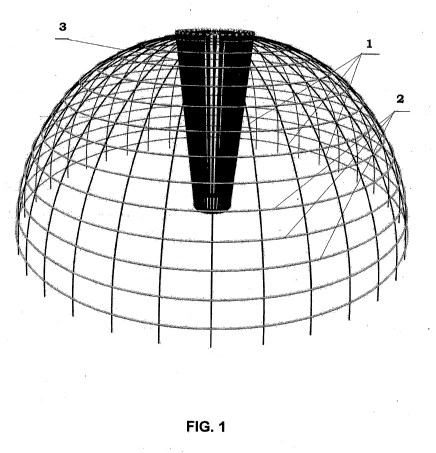
An example of the construction of a self-supporting three-dimensional
prestressed structure is shown in FIG. 1. The example shows a self-supporting
three-dimensional prestressed structure shaped as a hemisphere. The structure
is
constructed of vertical form-defining flexible rodlike members (1) stressed
CA 03031132 2019-01-17
WO 2018/014094 PCT/BG2017/000010
during the construction of the structure, as well as horizontally positioned
flexible rodlike members (2) each forming a circular contour. The horizontal
members which are also stressed are welded or rigidly joined by other means to
= the vertical form-defining rodlike members (1).
The horizontal circular contours are parallel to each other.
The device for construction of self-supporting three-dimensional prestressed
structures is shown as (3) on FIG. 1.
Instead of horizontal circular members (2) the structure can be constructed
completely or to some extent using a spiral member, also stressed during the
construction of the structure that is rigidly affixed to the vertical form-
defining
flexible members (1).
The device (3) for the construction of the self-supporting three-dimensional
prestressed structure and the implementation or the method comprises a number
of symmetrically and radially positioned telescopic arms (4) each hinged to a
circle (5) positioned at the center of the device FIG. 2. At the tip of each
telescopic arm (4) there is a guide block fixing (6) FIG. 3. In this
embodiment the
guide block (6) comprises two parallel plates or cheeks (7) fixed to the
telescopic
arm (4), whereas between said cheeks (7) are installed in sequence grooved
rollers (8). The opening between the rollers (8) is at least equal to the
cross-
sectional diameter of the vertical rodlike member (1) to be held between them.
By varying the lengths of the telescopic arms (4) it is possible to configure
three-
dimensional prestressed structures with different shapes.
The method for construction of self-supporting three-dimensional prestressed
structures, which also explains the operating principle of the device,
comprises
the following operations in the sequence below:
= 1. A site and of a geometric center for the structure are selected. If
the structure
6
CA 03031132 2019-01-17
WO 2018/014094 PCT/BG2017/000010
will be shaped as part of a sphere, such as a hemisphere (FIG. 4), the radius
of
the structure is also determined;
2. The site is leveled underneath the selected geometric center and a
foundation is
laid;
3. The material for the structure's framework is selected and prepared.
Commonly used materials are flexible members (1), made for instance of wood,
plastic or composite with rodlike or pipe profile;
4. The raster for the structure is determined, namely the number of the
vertical
and horizontal members for the intended structure with hemispherical (or more
complex) shape. The thickness of the material and the raster are determined
based on the intended purpose of the structure and the type of the material;
5. The device for construction of self-supporting three-dimensional
prestressed
structures (3) is then placed on the foundation and fixed to same;
The number of the telescopic arms (4) of the device corresponds to the number
of
the vertical rodlike members of the intended structure. When building a
hemisphere, the length of the telescopic arms (4) is a constant number equal
to
the radius of the structure. When building more complex shapes, the length of
each telescopic arm (4) can vary in each stage of the construction process, in
order to achieve the intended complex three-dimensional shape.
6. The vertical rodlike members (1) are placed at regular intervals along the
circumference of the intended structure, and then they are fed through the
guiding blocks (6) of the telescopic arms (4). For better stability, the
rodlike
members (1) can be anchored into prepared sockets underneath the guiding
blocks (6). The sockets can be prepared from sections of metal pipe with
inside
diameter greater than the diameter of the selected material that are driven
into the
foundation. If a concrete foundation is laid under the outside perimeter of
the
7
CA 03031132 2019-01-17
WO 2018/014094 PCT/BG2017/000010
- structure, the vertical flexible members can be affixed directly into the
concrete.
7. The next stage is the upward movement of the guiding blocks (6) of the
telescopic arms (4) along the corresponding vertical rodlike members (1) FIGS.
5
and 6. The movement of each guiding block (6) along the corresponding flexible
rodlike member (1) stresses it and forces is to form a circular arc.
The upward movement of all guiding blocks (6) along the vertical rodlike
members (1) can be either sequential or simultaneous.
8. A horizontal circular member (2) is placed and affixed (welded) around the
bent vertical rodlike members (1).
9. The upward movement of each telescopic arm (4) (at increments determined
by the selected raster) is sequentially alternated with the attachment of a
horizontal flexible rodlike member (2) (circular in the case of a hemisphere
or
with more complex closed-contour shape for a structure with a more complex
shape) ¨ FIGS 7 and 8. The horizontal flexible rodlike members (2) are affixed
rigidly to each vertical rodlike member (1) by means of a fitting or by
welding.
When each horizontal flexible rodlike member (2) is fully attached it fixes
all
vertical rodlike members (1) and equalizes their tension.
10. When the entire structure is complete the device (3) is in the
configuration
"all arms in a vertical bundle" FIG. 1. At this point the constructed three-
dimensional structure is fully self-supported, and all forces/vectors acting
on the
structure are in equilibrium. At this stage the device (3) can be removed from
the
structure and be ready for reuse.
11. If the design requires the making of openings in the structure (doors,
windows, etc.), the frames with the required dimensions and strength are made
first, and then affixed at the required positions. The bordering sections of
the
structure are affixed/welded regularly to the frames, and only then the excess
8
CA 03031132 2019-01-17
WO 2018/014094 PCT/BG2017/000010
parts of the structure enclosed in the frames are cut away. Any cutting of
unframed sections of the stressed structure would cause the abrupt release of
the
tension with catastrophic results.
12. The complete structure can be covered in waterproofing or other material,
or
in concrete, and it can be used for civic and production halls, residential
buildings, greenhouses, temples, swimming pools and other structures FIG. 9.
9