Note: Descriptions are shown in the official language in which they were submitted.
CA 03031216 2019-01-18
WO 2018/019346 PCT/DK2017/050229
1
Detecting parameter in flexible pipe system comprising a turret
Technical Field
The invention relates to a flexible pipe system comprising an unbonded
flexible
pipe with at least one optical fibre integrated in an armouring layer, where
the
unbonded flexible pipe is connected rotationally to a floating vessel via a
turret
and a swivel device. The invention also relates to a method of detecting at
least one parameter in an unbonded flexible pipe having at least one armour-
ing layer.
Background
Unbonded flexible pipes are well known in the art, in particular for offshore
transportation of fluids or gases. They can be used e.g. for the
transportation
of fluids where very high or varying water pressures exist along the
longitudinal
axis of the pipe. This is the case e.g. for so-called riser pipes extending
partly
or totally from the seabed up to an installation on or near the surface of the
sea, e.g. in the form of a floating vessel or a platform, or for pipes for
transpor-
tation of liquid and gases between installations, pipes which are located at
great depths on the seabed, or pipes between installations near the surface of
the sea.
Such pipes usually comprise a number of concentric layers, including an inner
liner, often also referred to as an inner sealing sheath or an inner sheath,
which
forms a barrier against the outflow of the fluid that is conveyed through the
pipe, and one or more armouring layers on the outer side of the inner liner.
Typically, at least one of the armouring layers comprises a plurality of
helically
wound elongated armouring elements arranged around the internal sealing
sheath. An outer sheath may be provided to provide a mechanical protection
and/or for forming a barrier against the ingress of fluids from the pipe
surround-
ings to the armouring layers.
CA 03031216 2019-01-18
WO 2018/019346 PCT/0K2017/050229
2
In this context, the term "unbonded" refers to the fact that at least two of
the
layers including the armouring layers and sheath layers are not bonded to each
other. In practice, an unbonded flexible pipe normally comprises at least two
armouring layers located outside the inner sealing sheath, where the armour-
.. ing layers are not bonded to each other or to other layers directly or
indirectly
via other layers along the pipe. The pipe layers can therefore move relative
to
each other, and thereby the pipe becomes highly bendable, usable for dynamic
applications, e.g. as risers, and sufficiently flexible to roll up for
transportation
even when the layers are relatively thick. This is necessary for high strength
.. pipes, which should be able to withstand high pressure differences over
layers
of the pipe, e.g. pressure differences between the pressure inside the bore of
the pipe and the pressure on the outer side of the pipe.
Unbonded flexible pipes can be very long, and since the production of oil is
performed at increasing water depths, the length as well as the requirement to
strength of the unbonded flexible pipe is increased as well. A main reason for
the increased requirements is that the greater the depth at which a flexible
pipe
is to be used, the higher the requirements will be to strength against
collapsing
due to external pressure. Furthermore, the weight of the pipe during deploy-
ment and use may result in high tensile forces, which increase with the length
of the pipe and the depth at the deployment site. The higher the strength that
needs to be provided, the more critical the integrity of individual tensile
armour-
ing elements becomes.
.. Therefore, armouring layers need to be monitored for potential breaks in
the
armouring elements, which could occur during use, even normal use, of the
pipe due to the stress that the unbonded flexible pipe is subjected to during
its
use, in particular when used as a riser.
.. One way of detecting a break of an elongated armouring element of an un-
bonded flexible pipe is to use a flexible pipe system, in which the unbonded
flexible pipe has a sensor system based on the use of one or more optical
CA 03031216 2019-01-18
WO 2018/019346 PCT/0K2017/050229
3
fibres at least partly integrated in at least one armouring layer of the
unbonded
flexible pipe.
Typically, the sensor system comprises interrogating equipment placed on the
sea surface installation and a plurality of optical fibre sensors integrated
in one
or more of the elongated armouring elements of an armouring layer. Each one
of these armouring elements has integrated therein at least one optical fibre
comprising a plurality of optical fibre sensors. The optical fibre sensors
extend
along a monitoring length section of the flexible pipe, and they are arranged
to
measure or determine a change in strain of the respective armouring elements
by transmitting a light signal from an optical transmitter in the
interrogating
equipment into the optical fibre and measuring in an optical detector light
that
is reflected from the fibre to the interrogating equipment. In the optical
detector,
or a computing unit to which it is connected, the reflected optical signals
are
processed for determining changes in e.g. intensity, phase, polarization, wave-
length, or transit time of light in the fibre, which indicate a change in the
strain
and/or temperature along the fibre or at one of the sensors.
In this way, the flexible pipe system can detect changes in strain that the
elon-
gated armouring elements experience, e.g. due to movements from waves
etc., change in internal pressure, change in buoyancy of the pipe, or other
influences. A special case of sudden change in strain is the breaking of an
elongated armouring element. Such a failure reduces the residual strength of
the flexible pipe and may ultimately result in catastrophic damage to the
pipe.
Therefore, in general a flexible pipe should be replaced after an elongated ar-
mouring element has broken, since this could indicate that other armouring
elements may be at risk of breaking soon.
Typically, several sensors are multiplexed along the length of the optical
fibre,
e.g. by using light wavelength shift for each sensor or by sensing the time
delay
as a light pulse passes along the fibre through each sensor. In addition to de-
termining a change in strain, optical fibres can also be used as sensors to
measure temperature, pressure and other quantities by modifying a fibre so
CA 03031216 2019-01-18
WO 2018/019346 PCT/0K2017/050229
4
that the quantity to be measured modulates e.g. the intensity, phase, polariza-
tion, wavelength, or transit time of light in the fibre.
In principle, any type of optical fibre strain sensors could be employed, but
fibre
Bragg gratings are particularly advantageous for this use, because fibre optic
sensors using fibre Bragg gratings can measure co-located temperature and
strain simultaneously with high accuracy. As an alternative to a plurality of
op-
tical fibre sensors arranged along a fibre integrated in one of the elongated
armouring elements of an armouring layer, distributed temperature sensing
along an optical fibre, which uses Raman-shifted backscatter from laser pulses
to determine the temperature along the optical fibre, may also be used. Dis-
tributed temperature sensing systems measure temperatures by means of the
optical fibre functioning as a linear sensor. Temperatures are recorded along
the optical fibre, i.e. not at points, but as a continuous profile.
By large water depths and/or in remote areas of the sea, the floating vessel
with the sea surface installation for the risers using unbonded flexible pipes
may typically be a floating production, storage and offloading (FPSO) unit,
which is a floating facility or ship to which the risers coming from the
seabed
are connected. The FPSO is equipped with processing equipment for separa-
tion and treatment of the fluid arriving on board from subsea installation via
the
risers. Due to the size of an FPSO, the vessel need to be able to rotate
freely
in horizontal direction according to the directions of winds, waves and sea
cur-
rents, while the risers remain connected to a fixed part on the seabed, and
material is still allowed to pass through. The free rotation of the FPSO
accord-
ing to weather conditions is also referred to as weathervaning. The FPSO will
normally lay head to the prevailing environment.
To allow the free rotation, an FPSO is equipped with a turret mooring system,
which is usually fitted inside and integrated into a substantially vertical
shaft,
chamber or compartment in the hull of the FPSO. A turret, which is typically
cylindrical, is moored to the seabed with chains, wires and/or anchors, and
CA 03031216 2019-01-18
WO 2018/019346
PCT/0K2017/050229
bearings allow free and unrestricted 360 rotation of the FPSO around the tur-
ret, which is thus the geostatic part of the turret mooring system. The risers
are
connected to the geostatic turret, and a fluid transfer path between the
turret
and the free weathervaning FPSO rotating around the turret is provided by a
5 .. swivel device. The turret system is fully passive and does not require
active
vessel heading control or active rotation systems in the turret or the swivel
device.
The swivel device may also be arranged to transmit electrical signals between
the turret and the free rotating FPSO. Some swivel devices also allow optical
signals to be transferred between the turret and the FPSO, typically by using
a fibre optic rotary joint having a plurality of optical transmitters and/or a
plu-
rality of optical receivers arranged on a rotor and a stator, respectively. In
such
a plural input/plural pickup system, a rise and fall of the received optical
signal
strength during rotation is inherent in combination with a large insertion
loss
and a large variation in loss and polarisation. This means that although
swivel
devices using fibre optic rotary joints may provide an acceptable performance
for the transmission of digitized optical signals, the performance for
transmis-
sion of analog optical signals through the swivel device is very poor because
the signals are distorted by the fibre optic rotary joint.
Thus, the optical signals reflected from a sensing fibre integrated in an un-
bonded flexible pipe to interrogating equipment placed on the FPSO cannot be
passed through a swivel device without being distorted to a degree that pre-
vents the sensor system from detecting changes in strain and/or temperature
in the unbonded flexible pipe. This means that on floating vessels equipped
with a turret mooring system to allow the free horizontal rotation of the
vessel
according to weather conditions, sensor systems based on optical fibres inte-
grated in an armouring layer of an unbonded flexible pipe cannot be used with
satisfactory results.
6
Summary
Therefore, it is an object of embodiments of the invention to provide a
flexible pipe system
comprising a sensor system having an optical fibre integrated in an armouring
layer of an
unbonded flexible pipe, which can also be used for detecting changes in a
parameter
such as strain and/or temperature in the unbonded flexible pipe on floating
vessels
equipped with a turret mooring system.
According to embodiments of the invention the object is achieved in that a
flexible pipe
system comprises an unbonded flexible pipe comprising at least one armouring
layer and
connected to a floating vessel; a sensor system adapted for detecting changes
in strain
and/or temperature in the unbonded flexible pipe and comprising at least one
optical fibre
integrated in the at least one armouring layer of the unbonded flexible pipe;
and
interrogating equipment having an optical transmitter configured to transmit
optical
signals into said at least one optical fibre; and an optical detector
configured to receive
optical signals reflected from said at least one optical fibre and to detect
therefrom at least
one parameter in said unbonded flexible pipe; wherein the flexible pipe system
comprises
a turret for rotationally connecting the unbonded flexible pipe to the
floating vessel, said
turret being supported by a substantially vertical shaft in the floating
vessel and
comprising an end-fitting for terminating and securing said unbonded flexible
pipe to the
turret; and a swivel device for rotationally connecting the turret to the
shaft of the floating
vessel and providing a fluid transfer passage between the turret and the
floating vessel,
wherein said interrogating equipment is located on said turret to provide that
optical
signals reflected from the fibre can reach the interrogating equipment without
being
distorted in the swivel device and is further configured to transfer signals
indicative of said
at least one detected parameter to receiving equipment on said floating vessel
and
wherein said interrogating equipment comprises a transmitter for transmitting
said signals
indicative of said at least one detected parameter to the receiving equipment
on said
floating vessel and wherein the flexible pipe system is configured to transmit
said signals
as wireless signals to the receiving equipment on said floating vessel.
When the interrogating equipment is arranged on the turret, it is achieved
that the optical
signals reflected from the fibre can reach the interrogating equipment without
being
Date Recue/Date Received 2022-05-11
7
distorted in a swivel device, so that parameters for the unbonded flexible
pipe can be
detected with a sufficient quality also in cases where a floating vessel is
equipped with a
turret mooring system. The possibility of transferring signals indicative of
the parameter
detected in the interrogating equipment to receiving equipment on the floating
vessel
ensures that the parameters of the unbonded flexible cable can still be
monitored e.g. by
monitoring equipment or personnel in a control room on board the floating
vessel.
In an embodiment, the interrogating equipment comprises a transmitter for
transmitting
said signals indicative of said at least one detected parameter to the
receiving equipment
on said floating vessel.
In this case, the flexible pipe system may be configured to transmit said
signals through
said swivel device, and the transmitter for transmitting said indicative
signals may be
configured to transmit the signals as analog electrical signals, digital
electrical signals or
digital optical signals. In case of digital electrical or digital optical
signals, the transmitter
for transmitting said indicative signals may be configured to transmit the
signals as
Ethernet signals.
Alternatively, the transmitter for transmitting said indicative signals may be
configured to
transmit the signals as wireless signals, or the interrogating equipment may
comprise a
storage medium for storing said indicative signals for subsequent manual
retrieval.
Expediently, the receiving equipment may be arranged in a local
instrumentation room on
said floating vessel, where the detected parameters can be monitored by
monitoring
equipment or personnel on board the floating vessel.
In an embodiment, said interrogating equipment is arranged in an enclosure
that is
certified according to ATEX Zone 1 and rated to IP68. This protects the
equipment against
the quite tough environment in the turret compartment.
In an embodiment, the floating vessel is a floating production, storage and
offloading unit,
FPSO.
Date Recue/Date Received 2022-05-11
8
The turret may be an internal turret located in the hull of said floating
vessel. This
embodiment is most useful in relatively harsh environments, among other things
because
the mooring forces can be transferred more easily into the hull of the
floating vessel.
Alternatively, the turret may be an external turret located in a projection
extending from
the hull of said floating vessel. This embodiment is mostly used in relatively
calm waters,
and it can easily be mounted e.g. on a tanker in order to convert the tanker
to an FPSO.
Expediently, the turret may have a cylindrical shape. This facilitates the
rotation in the
shaft of the floating vessel.
In an embodiment, the turret is configured to be separated along a
disconnection plane
into a lower part for receiving the unbonded flexible pipe and an upper part
comprising
the interrogating equipment. This allows the floating vessel to release the
lower part of
the turret and move to another position, e.g. in case of an emergency
situation, such as
a cyclone or an iceberg, or just to be connected to another turret at the
other position.
In an embodiment, the turret is configured to connect a plurality of unbonded
flexible pipes
to the floating vessel. This increases the capacity of the vessel
considerably.
In an embodiment, a plurality of optical fibre sensors are arranged along said
optical fibre.
The plurality of optical fibre sensors may be intrinsic sensors integrated in
said optical
fibre, and each one of said intrinsic sensors may then comprise a fibre Bragg
grating.
Alternatively, the plurality of optical fibre sensors may be extrinsic sensors
connected to
said optical fibre.
The sensor system may comprise a plurality of optical fibres integrated in
corresponding
armouring elements of an armouring layer of the unbonded flexible pipe, and
each of said
plurality of optical fibres may comprise a plurality of optical fibre sensors
arranged with
equal distances between them along the fibre, so that a plurality of optical
fibre sensors
Date Recue/Date Received 2022-05-11
9
are arranged at coinciding cross sections of the unbonded flexible pipe. This
improves
the accuracy of the measurements in the unbonded flexible pipe.
In embodiments in which a plurality of optical fibre sensors are arranged
along said optical
fibre, the sensor system may comprise at least one further optical fibre
integrated in an
armouring element of an armouring layer of the unbonded flexible pipe, and
said
interrogating equipment may be configured to perform distributed temperature
sensing by
transmitting laser pulses into said further fibre and determining temperatures
along said
further fibre based on Raman-shifted backscatter from said laser pulses. This
allows the
fibre with a plurality of optical fibre sensors to be used for strain
detection and the further
fibre to be used for temperature detection.
In other embodiments, the interrogating equipment may be configured to perform
distributed temperature sensing by transmitting laser pulses into said optical
fibre and
determining temperatures along said optical fibre based on Raman-shifted
backscatter
from said laser pulses.
As mentioned, the invention further relates to a method of detecting at least
one
parameter in an unbonded flexible pipe having at least one armouring layer in
a flexible
pipe system further comprising a turret for rotationally connecting the
unbonded flexible
pipe to a floating vessel, said turret being supported by a substantially
vertical shaft in the
floating vessel and comprising an end-fitting for terminating and securing
said unbonded
flexible pipe to the turret; a swivel device for rotationally connecting the
turret to the shaft
of the floating vessel and providing a fluid transfer passage between the
turret and the
.. floating vessel; and a sensor system for detecting said at least one
parameter and
comprising at least one optical fibre integrated in the at least one armouring
layer of the
unbonded flexible pipe, wherein said at least one parameter being changes in
strain
and/or temperature in the unbonded flexible pipe, and wherein the method
comprising the
steps of transmitting optical signals into said at least one optical fibre
from an optical
transmitter of an interrogating equipment arranged on said turret; receiving
optical signals
reflected from said at least one optical fibre and detecting therefrom at
least one
parameter in said unbonded flexible pipe in an optical detector of said
interrogating
Date Recue/Date Received 2022-05-11
10
equipment located on said turret; and transferring signals indicative of said
at least one
detected parameter to receiving equipment on said floating vessel from said
interrogating
equipment arranged on said turret; wherein the method further comprises the
step of
transmitting said signals indicative of said at least one detected parameter
to the receiving
equipment on said floating vessel from said interrogating equipment arranged
on said
turret as wireless signals.
When the optical signals reflected from the optical fibre are received and at
least one
parameter in said unbonded flexible pipe is detected therefrom in an optical
detector of
interrogating equipment arranged on the turret, it is achieved that the
optical signals
reflected from the fibre can reach the interrogating equipment without being
distorted in
a swivel device, so that parameters for the unbonded flexible pipe can be
detected with
a sufficient quality also in cases where a floating vessel is equipped with a
turret mooring
system. Transferring signals indicative of the detected parameter to receiving
equipment
on the floating vessel from the interrogating equipment arranged on the turret
ensures
that the parameters of the unbonded flexible cable can still be monitored e.g.
by
monitoring equipment or personnel in a control room on board the floating
vessel.
In an embodiment, the method further comprises the step of transmitting said
signals
indicative of said at least one detected parameter to the receiving equipment
on said
floating vessel from said interrogating equipment arranged on said turret.
In this case, the method may further comprise the step of transmitting said
indicative
signals through said swivel device, and the indicative signals may be
transmitted as
analog electrical signals, digital electrical signals or digital optical
signals. In case of digital
electrical signals or digital optical signals, the indicative signals may be
transmitted as
Ethernet signals.
Alternatively, the indicative signals may be transmitted as wireless signals,
or the
indicative signals may be stored on a storage medium in said interrogating
equipment for
subsequent manual retrieval.
Date Recue/Date Received 2022-05-11
10a
The invention further relates to a flexible pipe system comprising: an
unbonded flexible
pipe comprising at least one armouring layer and connected to a floating
vessel; a sensor
system adapted for detecting changes in strain and/or temperature in the
unbonded
flexible pipe and comprising: at least one optical fibre integrated in the at
least one
armouring layer of the unbonded flexible pipe; and interrogating equipment
having an
optical transmitter configured to transmit optical signals into said at least
one optical fibre;
and an optical detector configured to receive optical signals reflected from
said at least
one optical fibre and to detect therefrom at least one parameter in said
unbonded flexible
pipe; wherein the flexible pipe system comprises a turret for rotationally
connecting the
unbonded flexible pipe to the floating vessel, said turret being supported by
a substantially
vertical shaft in the floating vessel and comprising an end-fitting for
terminating and
securing said unbonded flexible pipe to the turret; and a swivel device for
rotationally
connecting the turret to the shaft of the floating vessel and providing a
fluid transfer
passage between the turret and the floating vessel, wherein said interrogating
equipment
is located below the swivel device to provide that optical signals reflected
from the fibre
can reach the interrogating equipment without being distorted in the swivel
device and is
further configured to transfer signals indicative of said at least one
detected parameter to
receiving equipment on said floating vessel and wherein said interrogating
equipment
comprises a transmitter for transmitting said signals indicative of said at
least one
detected parameter to the receiving equipment on said floating vessel as
wireless signals.
Date Recue/Date Received 2022-05-11
CA 03031216 2019-01-18
WO 2018/019346 PCT/0K2017/050229
11
Brief Description of the Drawings
Embodiments of the invention will now be described more fully below with ref-
erence to the drawings, in which
Figure 1 shows a floating production, storage and offloading (FPSO) unit hav-
ing a turret on which interrogating equipment is arranged for performing meas-
urements on an optical fibre integrated in an unbonded flexible pipe connected
to the turret;
Figure 2 shows an example of an unbonded flexible pipe comprising a number
of concentric layers;
Figure 3 shows an example of an optical fibre with a plurality of optical
fibre
sensors integrated in a helically wound armouring element of an armouring
layer in the unbonded flexible pipe of Figure 2;
Figure 4 shows an example of interrogating equipment for performing meas-
urements on the fibre of Figure 3;
Figure 5 shows a schematic cross-sectional side view of an example of an
end-fitting for terminating an unbonded flexible pipe in the turret of Figure
1;
Figure 6 shows an unbonded flexible pipe having four optical fibres with
optical
fibre sensors integrated in the armouring elements of an armouring layer;
Figure 7 shows the unbonded flexible pipe of Figure 6 having a further fibre
integrated in a helically wound armouring element of one of the armouring lay-
ers, which is used for distributed temperature sensing;
Figure 8 shows an example of interrogating equipment for performing meas-
urements on the fibres of the unbonded flexible pipe of Figure 7;
CA 03031216 2019-01-18
WO 2018/019346 PCT/0K2017/050229
12
Figure 9 shows a floating production, storage and offloading (FPSO) unit hav-
ing a turret on which interrogating equipment is arranged for performing meas-
urements on optical fibres integrated in four unbonded flexible pipes
connected
to the turret;
Figure 10 shows a floating production, storage and offloading (FPSO) unit hav-
ing a turret, which can be separated along a disconnection plane into a lower
part for receiving the unbonded flexible pipes and an upper part comprising
the interrogating equipment;
Figure 11 shows the turret of Figure 10 when the upper part and the lower part
have been separated from each other;
Figure 12 shows a floating production, storage and offloading (FPSO) unit hav-
ing an external turret, where the turret on which interrogating equipment is
ar-
ranged is located outside the hull of the ship; and
Figure 13 shows a flow chart illustrating a method of detecting a parameter in
an unbonded flexible pipe from interrogating equipment arranged on a turret
on a floating production, storage and offloading (FPSO) unit.
Detailed Description
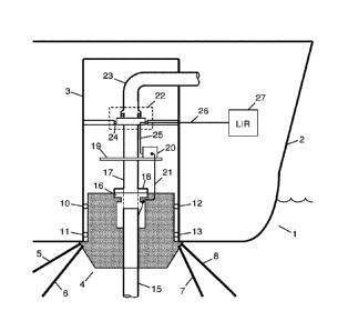
As an example of a floating vessel, in which the invention can be used, Figure
1 shows a floating production, storage and offloading (FPSO) unit 1 that can
be used as a sea surface installation in the offshore oil and gas industry for
separating, treating and storing liquids and/or gases arriving on board from
e.g. subsea oil wells via unbonded flexible pipes acting as so-called risers.
The
hull 2 of the FPSO 1 is provided with a substantially vertical shaft, chamber
or
compartment 3, typically having a cylindrical form, for receiving and
supporting
a turret 4. The typically cylindrical turret 4 is moored to the seabed by
chains
or wires 5, 6, 7 and 8 ensuring that the turret can maintain a geostatic
position.
The turret 4 also has bearings 10, 11, 12 and 13 between the turret and the
supporting shaft 3 allowing the FPSO 1 to rotate 360 in a horizontal plane
CA 03031216 2019-01-18
WO 2018/019346 PCT/0K2017/050229
13
freely and unrestricted around the geostatic turret 4 according to the
directions
of winds, waves and sea currents. The free rotation of the FPSO 1 according
to weather conditions is also referred to as weathervaning. A riser in the
form
of an unbonded flexible pipe 15 coming from the seabed is connected to the
turret 4 by means of an end-fitting 16.
An example of an unbonded flexible pipe 15 comprising a number of concentric
layers is illustrated in Figure 2. The flexible pipe 15 comprises a liquid
imper-
vious inner sealing sheath 32 defining a bore as indicated with the bold
arrow.
The inner sealing sheath 32, often also called an inner liner, can be made of
a
polymer material suitable for forming such liquid impervious barrier. The
inner
sealing sheath 32 has the purpose of preventing outflow of the fluid
transferred
in the bore of the pipe, indicated with the bold arrow.
Inside the inner sealing sheath 32, the unbonded flexible pipe comprises an
inner armour layer 31 called a carcass, which is normally of metal and has the
main purpose of reinforcing the unbonded flexible pipe against collapse.
On the outer side of the inner sealing sheath 32, the unbonded flexible pipe
comprises three outer armouring layers 33, 34 and 35. The outer armouring
layer 33 closest to the inner sealing sheath 32 is a pressure armour layer 33,
which is often made of helically wound armour elements of metal or composite
material, which is wound with a short pitch, i.e. with a steep angle to the
centre
axis of the unbonded flexible pipe, e.g. close to 90 degrees. The pressure ar-
.. mour layer 33 is not liquid tight.
Around the pressure armour layer 33, the unbonded flexible pipe comprises
two cross-wound tensile armour layers 34, 35 wound from elongate armour
elements, e.g. profiles and/or strips made of composite material and/or metal.
For example, the elongate armouring elements on the innermost tensile ar-
mour layer 34 are wound with a winding degree of about 55 degrees or less to
the axis of the unbonded flexible pipe in a first winding direction, while the
outermost tensile armour layer 35 is wound with a winding degree of about 60
CA 03031216 2019-01-18
WO 2018/019346 PCT/0K2017/050229
14
degrees or less to the axis of the unbonded flexible pipe in a second winding
direction, which is the opposite direction to the first winding direction. The
two
armour layers with such opposite winding direction are normally referred to as
being cross-wound.
The unbonded flexible pipe further comprises a liquid impervious outer sealing
sheath 36, which protects the armour layers mechanically and against ingress
of sea water.
This type of flexible pipe is called unbonded because at least two of the
layers
including the armouring layers and sheath layers are not bonded to each other.
In practice, the armouring layers are not bonded to each other or to other
layers
directly or indirectly via other layers along the pipe. The pipe layers can
there-
fore move relative to each other, and thereby the pipe becomes highly benda-
ble, usable for dynamic applications e.g. as risers, and sufficiently flexible
to
roll up for transportation even when the layers are relatively thick.
In order to be able to monitor armouring layers, e.g. one of the layers 33, 34
and 35, of the unbonded flexible pipe 15 for potential breaks in the helically
wound armouring elements, which could occur during use of the pipe due to
the stress that the unbonded flexible pipe is subjected to during its use, the
unbonded flexible pipe may be provided with one or more optical fibres at
least
partly integrated in one or more armouring elements of at least one armouring
layer of the unbonded flexible pipe.
Figure 3 shows an example of an optical fibre 41 integrated in an unbonded
flexible pipe 15. Since the fibre 41 is integrated in a helically wound
armouring
element of one of the armouring layers 33, 34 and 35, the pitch of the fibre
41,
i.e. the angle to the centre axis of the unbonded flexible pipe, corresponds
to
that of the armouring element. Along the fibre 41, a plurality of optical
fibre
sensors 42 are arranged to measure or detect changes in e.g. strain or tem-
perature of the armouring element on their respective locations. The optical
fibre sensors 42 are arranged with equal distances between them so that
CA 03031216 2019-01-18
WO 2018/019346 PCT/0K2017/050229
measurements can be performed at corresponding cross sections 43 of the
unbonded flexible pipe 15.
The measurement or detection of changes in strain or temperature along the
5 fibre 41 is performed by transmitting a light signal into one end of the
fibre and
detecting light that is reflected from the fibre. To this purpose,
interrogating
equipment is used. Figure 4 illustrates an example of interrogating equipment
connected to the fibre 41. An optical transmitter 51 generates an optical
signal and transmits it into the fibre 41. As described in further detail
below,
10 light is reflected from each sensor 42 in the fibre 41 and then received
and
processed in an optical detector 52. Light reflected from the individual
optical
fibre sensors 42 can be distinguished e.g. by using light wavelength shift for
each sensor or by sensing the time delay as a light pulse passes along the
fibre 41 through each sensor. A controller 53 controls the optical transmitter
51
15 to transmit light, i.e. light pulses or continuous light and the
wavelength of the
light, and the optical receiver 52 to receive the reflected light, e.g. at the
right
times and at the right wavelengths. The controller 53 may also analyse the
reflected light in order to determine the parameters to be measured, such as
temperature and strain along the unbonded flexible pipe, or it may just
convert
20 the received light values to a more robust signal type and transmit them
to
further computation elsewhere on the FPSO 1, e.g. in a local instrumentation
room. To be able to transmit signals representing determined parameters or
received light values to such other location, the interrogation equipment 20
further comprises an Ethernet switch 54 connected to a cable 55, which may
be a twisted pair or a fiber optic link. In other embodiments, the signals
repre-
senting determined parameters or received light values may be transmitted to
the instrumentation room according to other protocol types or as analog elec-
trical or optical signals. Another possibility is to transmit the signals
wirelessly
to the instrumentation room. Alternatively, the data can be stored on a
storage
medium or memory 57 in the interrogation equipment 20 and subsequently
retrieved manually at a certain frequency. The storage medium 57 can be any
storage medium suitable for storing data. As examples can be mentioned
memory cards, USB sticks, CD-ROMs, DVDs or a hard disk.
CA 03031216 2019-01-18
WO 2018/019346 PCT/0K2017/050229
16
Normally, the optical fibre sensors 42 are integrated in the fibre 41 itself
as so-
called intrinsic sensors. Different types of optical fibre sensors can be em-
ployed, but fibre Bragg gratings are particularly advantageous for this use,
be-
cause fibre optic sensors using fibre Bragg gratings can measure co-located
temperature and strain simultaneously with high accuracy. A fibre Bragg grat-
ing is a distributed Bragg reflector constructed in a short segment of the
optical
fibre that reflects particular wavelengths of light and transmits all others.
This
is achieved by a periodic variation in the refractive index of the fibre core,
which
provides a wavelength-specific dielectric mirror. The Bragg wavelength is sen-
sitive to strain as well as to temperature. Thus, fibre Bragg gratings can be
used as sensing elements for one of these parameters in optical fibre sensors,
because the parameters cause a shift in the Bragg wavelength, which can then
be detected in the optical detector 52.
Instead of using intrinsic sensors integrated in the fibre 41 itself, the
fibre may
also just be used as a means of relaying signals from remote non-fibre optical
sensors to the interrogating equipment, which is referred to as extrinsic sen-
sors.
As shown in Figure 1, the unbonded flexible pipe 15 is connected to or
received
by the turret 4 by means of an end-fitting 16. In this embodiment, the turret
4
further comprises a pipe 17 connected to the end-fitting 16 by means of a
flange 18, so that the flow of liquids and/or gases arriving on board the FPSO
.. 1 from e.g. subsea oil wells via the unbonded flexible pipe 15 continues
through the pipe 17. A platform 19 on which the interrogating equipment 20
can be arranged is attached to the pipe 17. Alternatively, the interrogating
equipment 20 can be arranged directly at the top side of the turret 4 itself
next
to the flange 18.
The environment in the turret compartment can be quite tough, and therefore,
the interrogating equipment 20 is arranged in an enclosure 56 that is
certified
CA 03031216 2019-01-18
WO 2018/019346 PCT/0K2017/050229
17
according to ATEX Zone 1, i.e. a place in which an explosive atmosphere con-
sisting of a mixture with air of dangerous substances in the form of gas,
vapor
or mist is likely to occur in normal operation occasionally. The enclosure 56
is
further rated to IP68, and it is designed with an ambient temperature rating
of
-40 C to +60 C.
To connect the fibre 41 to the interrogating equipment at the end of the un-
bonded flexible pipe 15, the end-fitting 16 can be provided with a fibre exit
cavity with means for connecting the fibre 41 via the end-fitting 16 to the
inter-
rogating equipment or to another waveguide leading to the interrogating equip-
ment.
Figure 5 illustrates a schematic cross-sectional side view of an example of an
assembly of the flexible pipe 15 and the end-fitting 16, wherein the optical
fibre
has an overlength in the fibre exit cavity of the end-fitting. As in Figure 2,
the
unbonded flexible pipe 15 comprises an outer sealing sheath 36 surrounding
two cross-wound tensile armour layers 34 and 35. Inside the cross-wound ten-
sile armour layers 34 and 35, the pipe comprises a number of other layers,
including e.g. the carcass 31, the inner sealing sheath 32 and the pressure
armour layer 33. The layers 31, 32 and 33 inside the cross-wound tensile ar-
mour layers 34 and 35 will usually be terminated individually, as shown sche-
matically in the drawing with the terminating unit 61.
The end-fitting 16 comprises an annular end-fitting body structure 62 and an
annular outer casing 63. The end-fitting body structure 62 comprises an end-
fitting body 64 with a narrow section 65, a housing cavity 66, and a mounting
flange 67 with holes 68 for mounting to another part, e.g. the turret 4. The
housing cavity 66 is formed between the end-fitting body 64 and the outer cas-
ing 63. The outer sealing sheath 36 is terminated at a termination point 69 in
well known manner. The tensile armour elements of the tensile armour layers
34 and 35 are terminated and secured by securing material in the housing
cavity 66 of the end-fitting 16.
CA 03031216 2019-01-18
WO 2018/019346 PCT/0K2017/050229
18
The end-fitting 16 further comprises a fibre exit cavity 71 with an entrance
end
72 and an exit opening 73 through which the fibre 41 can exit. The fibre is
applied in an overlength in the fibre exit cavity 71, which means that the
optical
fibre section in the exit cavity 71 is longer than the length from the
entrance
end 72 to the exit opening 73 of the exit cavity.
In this embodiment, the end-fitting 16 comprises a lid 74 covering the exit
opening 73. The optical fibre 41 is terminated in the exit cavity 71 in that
it is
at least temporally fixed to the lid 74. The end-fitting 16 comprises a fibre
guide
unit 75 arranged in the housing cavity 66 and the optical fibre 41 is passing
through said fibre guide unit 75. Alternatively, the fibre may be terminated
within the exit cavity 71 and mounted with a connector for fast and simple
mounting to e.g. the interrogating equipment 20 or a waveguide leading to the
interrogating equipment 20. A lid may then cover the exit cavity 71 at its
exit
opening 73 to protect the fibre against dust and dirt and simultaneously ensur-
ing a mechanical protection. In use, the lid can be removed and the fibre con-
nector can be withdrawn for connection to the interrogating equipment 20.
In Figure 1, an optical fibre 21, or another type of optical waveguide,
connects
the optical fibre 41 to the interrogating equipment 20, but as mentioned, the
overlength of the fibre 41 in the exit cavity 71 may also be sufficiently long
for
connecting the fibre 41 directly to the interrogating equipment 20. Since the
interrogating equipment 20 is placed on the geostationary turret 4, a connec-
tion of sufficient quality between the optical fibre 41 and the interrogating
equipment 20 is ensured, even when the FPSO 1 rotates around the turret 4
according to changing weather conditions.
A swivel device 22 joins the pipe 17 on the geostationary turret 4 with
another
pipe 23, which is a part of the FPSO 1 and thus able to turn with respect to
the
geostationary turret 4. The pipe 23 leads to processing equipment and/or stor-
age on the FPSO. In this way, the swivel device 22 provides a fluid transfer
path between the turret 4 and the free weathervaning FPSO 1 when the FPSO
rotates around the turret. Through a slip ring 24, the swivel device 22 can
CA 03031216 2019-01-18
WO 2018/019346
PCT/0K2017/050229
19
transmit electrical signals between the turret 4 and the FPSO 1. In this case,
an electrical output signal from the interrogation equipment 20 can be trans-
mitted via the electrical connection 25, the slip ring 24 and the electrical
con-
nection 26 to a local instrumentation room 27 placed on board the FPSO 1.
This connection can of course also be used to control the interrogating equip-
ment 20 from the local instrumentation room 27. As mentioned above, this
connection may typically be an Ethernet connection.
It is noted that the slip ring 24 may also allow optical signals to be
transferred
between the turret and the FPSO, typically by using a fibre optic rotary joint
having a plurality of optical transmitters and/or a plurality of optical
receivers
arranged on a rotor and a stator, respectively. However, in such a plural in-
put/plural pickup system, a rise and fall of the received optical signal
strength
during rotation is inherent in combination with a large insertion loss and a
large
variation in loss and polarisation. This means that although a swivel device
using a fibre optic rotary joint may provide an acceptable performance for the
transmission of digitized optical signals, e.g. Ethernet signals, the
performance
for transmission of analog optical signals through the swivel device is very
poor
because the signals are distorted by the fibre optic rotary joint. Thus, the
optical
signals reflected from the sensing fibre 41 integrated in the unbonded
flexible
pipe 15 cannot be passed through a swivel device without being distorted to a
degree that prevents the sensor system from detecting changes in strain
and/or temperature in the unbonded flexible pipe 15. This problem is avoided
by placing the interrogating equipment 20 on the geostationary turret 4.
In Figure 3, an unbonded flexible pipe 15 with a single optical fibre 41 inte-
grated in a helically wound armouring element of one of the armouring layers
was shown. To improve the measurements of strain and/or temperature in the
pipe, an unbonded flexible pipe may be provided with several optical fibres
integrated in corresponding armouring elements. As an example, Figure 6
shows an unbonded flexible pipe 80 having four optical fibres 81, 82, 83 and
84 integrated in the armouring elements.
CA 03031216 2019-01-18
WO 2018/019346 PCT/0K2017/050229
Along each fibre, a plurality of optical fibre sensors 85 are arranged to
measure
or detect changes in e.g. strain or temperature of the armouring element on
their respective locations. As in Figure 3, the optical fibre sensors 85 of
each
fibre are arranged with equal distances between them, and in this embodiment,
5 sensors 85 belonging to different optical fibres are arranged so that
measure-
ments can be performed at coinciding cross sections 86 of the unbonded flex-
ible pipe 80. To perform the measurements of strain and/or temperature along
the four fibres 81, 82, 83 and 84, the optical transmitter 51 and the optical
receiver 52 of the interrogating equipment 20 may be multiplexed between the
10 fibres, or the interrogating equipment 20 may have separate transmitters
and
receivers for each fibre.
Instead of, or as a supplement to, using fibres having a plurality of optical
fibre
sensors arranged along the fibre integrated in one of the elongated armouring
15 elements of an armouring layer as shown in Figures 3 and 6, distributed
tem-
perature sensing along an optical fibre, which uses Raman-shifted backscatter
from laser pulses to determine the temperature along the optical fibre, may
also be used. Distributed temperature sensing systems measure temperatures
by means of the optical fibre functioning as a linear sensor. Temperatures are
20 recorded along the optical fibre, i.e. not at points, but as a
continuous profile.
Distributed temperature sensing is based on the fact that physical measure-
ment dimensions, such as temperature or pressure and tensile forces, can af-
fect a glass fibre and locally change the characteristics of light
transmission in
the fibre. As a result of the damping of the light in the quartz glass fibre
through
light scattering, also known as Raman scattering, occurring in the optical
fibre,
the location of an external physical effect can be determined so that the
optical
fibre can be employed as a linear sensor. The optical fibre is passive in
nature
and has no individual sensing points.
Thus, Figure 7 shows an unbonded flexible pipe 90 having a further fibre 91 in
addition to the four fibres 81, 82, 83 and 84 of Figure 6. Like the four
fibres 81,
82, 83 and 84, the fibre 91 is integrated in a helically wound armouring
element
CA 03031216 2019-01-18
WO 2018/019346 PCT/0K2017/050229
21
of one of the armouring layers, but in contrast to the fibres 81, 82, 83 and
84,
the fibre 91 does not have any optical fibre sensors arranged along the length
of the fibre. Instead, the fibre 91 is used for distributed temperature
sensing as
described above.
Figure 8 shows an example of an interrogating equipment 92 for use with the
unbonded flexible pipe 90 having fibres 81, 82, 83 and 84 with optical fibre
sensors arranged along the length of the fibre as well as a fibre 91 used for
distributed temperature sensing. The interrogating equipment 92 comprises a
strain interrogator 93 for detecting variations in strain via the fibres 81,
82, 83
and 84 and a distributed temperature sensing (DTS) interrogator 94 for detect-
ing variations in temperature via the fibre 91. Similarly to the interrogating
equipment 20 of Figure 4, the strain interrogator 93 comprises an optical
trans-
mitter 51, an optical detector 52 and a controller 53 to control the optical
trans-
mitter 51 to transmit light and the optical receiver 52 to receive light
reflected
from the optical fibre sensors 85 of the fibres 81, 82, 83 and 84. The DTS
interrogator 94 comprises an optical transmitter 95 for generating laser
pulses
and emitting them into the fibre 91 and an optical detector 96 for receiving
optical signals reflected from the fibre 91. From a delay profile of the
reflected
signals the optical detector 96 can determine temperature variations along the
fibre 91 and thus along the unbonded flexible pipe 90. A controller 97
controls
the functions of the optical transmitter 95 and the optical detector 96.
In Figure 8, the fibres 81, 82, 83, 84 and 91 are shown as being directly con-
nected to the interrogation equipment 92, which means that each one of these
fibres has an overlength in an exit cavity of the end fitting 16 that is
sufficiently
long for connecting the fibre directly to the interrogating equipment 92.
Alter-
natively, a separate optical fibre, or another type of optical waveguide, may
connect each of the fibres 81, 82, 83, 84 and 91 to the interrogating
equipment
20 by using optical connectors in the exit cavities of the end fitting 16. It
is also
noted that in this situation, the line representing the fibre 21 in Figure 1
repre-
sents the five fibres connected to the fibres 81, 82, 83, 84 and 91,
respectively,
in the exit cavities of the end fitting 16.
CA 03031216 2019-01-18
WO 2018/019346 PCT/0K2017/050229
22
To be able to transmit signals representing determined parameters or received
light values to further computation elsewhere on the FPSO 1, e.g. in a local
instrumentation room, the interrogation equipment 92 also comprises an Ether-
net switch 54 connected to a cable 55, which may be a twisted pair or a fiber
optic link. The Ethernet switch 54 is also connected to the controllers 53 and
97 so that the instrumentation room can receive information from and send
instructions to the strain interrogator 93 as well as the DTS interrogator 94.
In some embodiments, several risers in the form of unbonded flexible pipes
coming from the seabed may be connected to the same turret. An example of
this is shown in Figure 9, where the turret 104 receives four unbonded
flexible
pipes 105, 106, 107 and 108. Similarly to Figure 1, each unbonded flexible
pipe 105, 106, 107 and 108 is connected to or received by the turret 104 by
means of an end-fitting 116. A pipe 117 is connected to each end-fitting 116,
so that the flow of liquids and/or gases arriving on board the FPSO 1 from
e.g.
subsea oil wells via the unbonded flexible pipes 105, 106, 107 and 108 contin-
ues through the corresponding pipes 117. The four pipes 117 are combined to
the main pipe 17, so that the flow of liquids and/or gases from all four
unbonded
flexible pipes 105, 106, 107 and 108 can be transferred through the pipe 17,
the swivel device 22 and the pipe 23 to processing equipment and/or storage
on the FPSO.
As in Figure 1, each optical fibre of one of the unbonded flexible pipes 105,
106, 107 and 108 is connected to the interrogating equipment 120 by an optical
connection 121, e.g. an optical fibre or another type of optical waveguide, or
the overlength of the fibre in the exit cavity 71 of the corresponding end
fitting
116 may be sufficiently long for connecting the fibre directly to the
interrogating
equipment 120. Thus, as examples, if an unbonded flexible pipe 15 having
only one integrated fibre 41 as shown in Figure 3 is used, the optical connec-
tion 121 can be a single optical fibre, while it can consist of five optical
fibres
connected to the fibres 81, 82, 83, 84 and 91, respectively, if unbonded
flexible
CA 03031216 2019-01-18
WO 2018/019346 PCT/0K2017/050229
23
pipe 90 having five integrated fibres as shown in Figure 7 is used. The
interro-
gating equipment 120 may comprise interrogators for each one of the four un-
bonded flexible pipes 105, 106, 107 and 108, or separate interrogating equip-
ment may be used for each unbonded flexible pipe.
In another embodiment, a turret may be separated into two parts, which is il-
lustrated with the turret 124 in Figure 10, which can be separated along the
disconnection plane 125 into a lower part 126 for receiving the unbonded flex-
ible pipes 105, 106, 107 and 108 in the end fittings 116 and an upper part 127
comprising the pipes 17 and 117 and the platform 19 for the interrogating
equipment 120. This allows the FPSO to release the lower part 126 of the
turret
and move to another position, e.g. in case of an emergency situation, such as
a cyclone or an iceberg, or just to be connected to another turret at the
other
position. The lower part 126 of the turret will then sink beneath the waves
and
can be reconnected later.
To facilitate such disconnection, each unbonded flexible pipe 105, 106, 107
and 108 is provided with a valve 128 that allows the flow of liquids and/or
gases
from that pipe to be cut off before disconnection. Also each optical fibre 121
connecting the end fitting 116 to the interrogating equipment 120 is arranged
to be disconnected by dividing the fibre into two sections that can be
connected
to each other by means of optical connectors129. Since the connector parts of
the optical connector 129 can be left below the water when disconnected, so-
called subsea wet-mate connectors must be used.
In a situation where the lower part 126 of the turret 124 should be separated
from the FPSO 1, the valves 128 are closed and the upper part 127 and the
lower part 126 are then separated from each other as illustrated in Figure 11.
Normally, the upper part 127 will remain in the FPSO 1.
In the embodiments described above, the invention is described in relation to
a so-called internal turret, where the turret is located in the hull of a
vessel, i.e.
in this case the FPSO 1. Typically, the turret is located in the front end of
the
CA 03031216 2019-01-18
WO 2018/019346 PCT/0K2017/050229
24
FPSO, but in some cases, the turret can be found in the middle of the ship.
However, the invention can also be used in combination with an external
turret,
where the turret is located outside the hull of the ship, e.g. at the bow or
stern
of the vessel.
An example of this is shown as the FPSO 131 in Figure 12. The hull 132 of the
FPSO 131 is provided with a projection 135, e.g. at the bow of the FPSO 131.
This projection 135 has a substantially vertical shaft, chamber or compartment
133 for receiving and supporting the turret 134. Similarly to the turret 4 in
Fig-
ure 1, the turret 134 is moored to the seabed by chains or wires 5, 6, 7 and 8
ensuring that the turret can maintain a geostatic position, and a riser in the
form of an unbonded flexible pipe 15 coming from the seabed is connected to
the turret 134 by means of an end-fitting 16. The upper part of the turret 134
comprises a pipe 17 connected to the end-fitting 16, so that the flow of
liquids
and/or gases arriving on board the FPSO 131 from e.g. subsea oil wells via
the unbonded flexible pipe 15 continues through the pipe 17. A platform 19 on
which the interrogating equipment 20 can be arranged is attached to the pipe
17. Alternatively, the interrogating equipment 20 can be arranged directly at
the top side of the turret 134 itself.
An optical fibre 21, or another type of optical waveguide, connects the
optical
fibre of the unbonded flexible pipe 15 to the interrogating equipment 20, but
as
mentioned earlier, the overlength of the fibre 41 in the exit cavity 71 of the
end-
fitting 16 may also be sufficiently long for connecting the fibre 41 directly
to the
interrogating equipment 20. Since the interrogating equipment 20 is placed on
the geostationary turret 134, a connection of sufficient quality between the
op-
tical fibre 41 and the interrogating equipment 20 is ensured, even when the
FPSO 131 rotates around the turret 134 according to changing weather con-
ditions.
A swivel device 22 joins the pipe 17 on the geostationary turret 4 with
another
pipe 23, which is a part of the FPSO 131 and thus able to turn with respect to
the geostationary turret 134. The pipe 23 leads to processing equipment
CA 03031216 2019-01-18
WO 2018/019346
PCT/0K2017/050229
and/or storage on the FPSO. In this way, the swivel device 22 provides a fluid
transfer path between the turret 134 and the free weathervaning FPSO 131
when the FPSO rotates around the turret. Through a slip ring, the swivel
device
22 can transmit electrical signals between the turret 134 and the FPSO 131.
5 In this case, an electrical output signal from the interrogation
equipment 20 can
be transmitted via the electrical connection 25, the swivel device 22 and the
electrical connection 26 to a local instrumentation room 27 placed on board
the FPSO 131. This connection can of course also be used to control the in-
terrogating equipment 20 from the local instrumentation room 27. As men-
10 tioned above, this connection may typically be an Ethernet connection.
Figure 13 shows a flow chart 200 illustrating a method of detecting a parame-
ter, such as a temperature or strain value, in an unbonded flexible pipe
having
one or more optical fibres integrated in an armouring layer, where the un-
15 bonded flexible pipe is connected rotationally to a floating vessel via
a turret
and a swivel device as described above. In step 201, optical signals are trans-
mitted into the one or more optical fibres from an optical transmitter in
interro-
gating equipment that is arranged on the turret, so that the optical fibre can
be
connected to the interrogating equipment without having to pass through a
20 swivel device. In step 202, optical signals reflected from the optical
fibre in
response to the optical signals transmitted into the fibre in step 201 are re-
ceived in an optical detector in the interrogating equipment that is arranged
on
the turret, and the parameter of the unbonded flexible pipe is detected from
the optical signals received from the fibre. Finally, in step 203, signals
indica-
25 tive of the detected parameter is transferred to receiving equipment
placed on
the floating vessel from the interrogating equipment that is arranged on the
turret. As described above, this can be done by transmission through the
swivel device, by wireless transmission or by storing the data on a storage
medium in the interrogation equipment for subsequent manual retrieval at a
certain frequency.
Although various embodiments of the present invention have been described
and shown, the invention is not restricted thereto, but may also be embodied
CA 03031216 2019-01-18
WO 2018/019346 PCT/0K2017/050229
26
in other ways within the scope of the subject-matter defined in the following
claims.