Note: Descriptions are shown in the official language in which they were submitted.
A PILLOW THAT FACILITATES THE LATERAL SNIFF POSITION, IMPROVED
AIRWAY MANAGEMENT AND COMFORT
TECHNICAL FIELD
[1] The present disclosure relates to an apparatus (herein also referred to
as a pillow or a
head-positioning apparatus) for airway management that can provide support for
the head and
neck of a user while aligning the oropharyngeal, laryngeal, and tracheal axes
of the human
head and neck for airway management in the lateral decubitus position.
BACKGROUND
[2] Many attempts have been made to design and improve pillows in order to
reduce
snoring or other obstructive breathing, and/or to facilitate intubation.
Obstructive breathing
may occur during sleep, or sedation, most commonly in the supine position due
to the effects
of gravity on the tongue. Pillows have been developed to reduce airway
obstruction in the
supine position. For example, U.S. Pat. No. 5,048,136 discloses such a pillow.
Sleeping in
the lateral decubitus position (wherein person sleeps on their side) has been
also shown to
help reduce, but not eliminate, obstructive breathing during sleep. Because of
this known fact,
pillows that facilitate sleeping in the lateral position have been developed
to keep the airways
open including those disclosed in US. Pat. Nos. 7,908,691 B2 and 8,677,531B2.
[3] As described in U.S. Patent No. 8,677,531B2, one method of opening the
airways
includes aligning the oropharyngeal, laryngeal and tracheal axes by placing
the patient into
the "sniff" position, which has been determined to be the most effective
positional method for
improving the patency of the airway and therefore enhancing the volume and
smoothness of
the flow of air or oxygen into the patient and the flow of carbon dioxide out.
[4] However, there are shortcomings with conventional methods of managing
air and
oxygen flow through an individual's airway. For example, the conventional
methods fail to
accommodate the following: varying patient morphologies (for example variances
in shoulder
to neck distance or neck and jaw length), differing mattress compression
caused by variations
-1-
CA 3031286 2019-01-22
in user weight, and differences in mattress indentation force deflection (a
measure of softness
or firmness of a pillow or sleep mattress), all of which can prevent a patient
from sleeping
comfortably. The method described in the referenced patent also allows a
sleeping patient to
easily move from the lateral decubitus position into the supine position
wherein the alignment
of the axes of airways is lost and the luminal diameter of the airways is
diminished.
151 Thus a need exists for a pillow that is more effective in promoting
restful sleep while
aligning and/or increasing the diameter of the upper airways (those proximal
to the
cartilaginous trachea). This improvement should include features that allow
adjustments for
differing patient morphologies such as varying neck to shoulder measurements
for shoulder
depth, for differences in patient weight and mattress deformation (affecting
required pillow
height), for the use of ventilation devices (such as CPAP or BiPAP), for
comfortable
disposition of the arm during sleep and for varying the chin angle (head size,
patient height,
shoulder width, patient weight, chin length, range of motion (or lack
thereof), of the patients'
neck), thus allowing the patient to sleep in the most comfortable position
with optimal
alignment of the oropharyngeal, laryngeal, and tracheal axes.
SUMMARY
[6] Embodiments of the present invention address and overcome one or more
of the above
shortcomings and drawbacks, by providing methods, systems, and apparatuses for
positioning
and maintaining the user comfortably into the lateral sniff position.
171 In one embodiment, an apparatus for supporting the neck and the head of
a user for
airway management includes a top section with a top surface and a bottom
mating surface,
where the top surface is located on a side opposite the bottom mating surface;
a bottom
section with a bottom surface and a top mating surface, the top section mating
surface fitting
snuggly onto the bottom section mating surface where the indentation
deflection load (IDL) of
one section can be greater than the IDL of the second section; where the
bottom mating
surface of the top section and top mating surface of the bottom section fit
snugly together
through opposing interfaces and where the opposing interfaces are of
sufficient height and
depth to prevent the sections from sliding or moving relative to one another;
where the height
-2-
CA 3031286 2019-01-22
of either the top or bottom sections can vary such that differing user neck
and shoulder
lengths can be accommodated; where a cut-out on a portion of the pillow,
parallel to the
user's body accommodates the lateral extension and comfortable anatomic
positioning of both
arms, and especially the dependent arm, of the user.
[8] In some embodiments, the top section of the pillow can include a
removable and
replaceable segment that can be removed to provide access to the user's mouth
and nose, e.g.,
to accommodate a ventilation device. Further, in some embodiments, the pillow
can include a
left head-receiving portion and a right head-receiving portion for receiving
and supporting a
user's head in the left and the right lateral decubitus position. A ridge or
raised surface can
separate the left head-receiving portion from the right head-receiving
portion. The ridge or
raised surface between the first and second head-receiving portions assists in
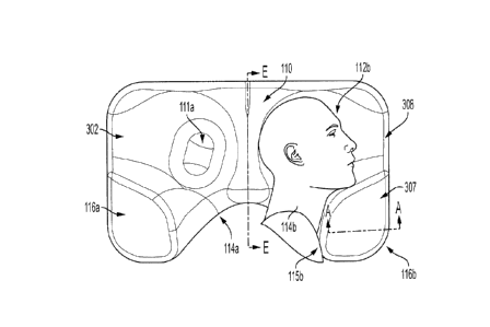
preventing the
user from inadvertently assuming (or consciously attempting) the supine
position while also
positioning the user's head into the proper lateral and sniff position or
lateral sniff ramp
position. In some embodiments, the ridge can have a non-uniform height with a
maximum
height in a range of about 1 to about 4 inches, e.g., 2.5 inches to about 3.5
inches, relative to
the bottom of the head-receiving portions. A left neck supporting surface is
connected to the
left head-receiving surface and a right neck supporting surface is connected
to the right head-
receiving surface, where the neck supporting surfaces are dimensioned to
support the user's
neck.
[9] The top section of the pillow can further include at least one chin
support for
facilitating the placement of a user in a lateral decubitus position. In some
such embodiments,
the height of the chin support can vary between 1 inch and 4.5 inches so that
the topmost
surface of the chin support is not higher than user's ear aperture level to
the top of the
epicanthus or outer corner of the down side eye, thus preventing
claustrophobia tendencies on
user's part and/or obstruction of the user's visual axis. The surfaces of both
head-receiving
portions, the ridge or raised surface between the head-receiving portions, and
the chin support
can collectively align the user's oropharyngeal, laryngeal and tracheal
airways in the sniff
lateral position with the user's head received in one of the head-receiving
portions. In many
embodiments, the chin support has a compound slope on its inner surface which
can be the
-3-
CA 3031286 2019-01-22
mirror image of the compound slope of the neck and platysmal surface of the
side of the
user's neck allowing the inner surface to comfortably receive said lateral
platysmal surface.
[10] In some embodiments, the recess neck openings (herein also referred to
as neck
channels) can be angled relative to the shoulder-receiving portions to
position the user's head
and neck in an anterior direction, thus allowing for lower neck flexion. The
chin support and
ear aperture triangulate the user to permit the head and upper neck to be in
an extension
position.
[11] In one embodiment, an apparatus for supporting the neck and head of a
user for airway
management includes one or more head-receiving portions shaped and dimensioned
to
support the side of a user's head, a chin support that includes an adjustable
chin positioner
that can be adjusted to support the chin of a user, and a neck supporting
surface shaped and
dimensioned to support a side of the user's neck; wherein the depth of the
recessed surface
corresponding to the user's chin can be approximately 2 inches, the depth of
the recessed
portion of the head-supporting surface can be approximately 3 inches and the
depth of a
recessed portion of the head supporting surface corresponding to the back of
the user's head
can be approximately 3 inches, and where the adjustable chin positioner can
allow the user's
Occipito-Atlanto-Axial joint to be adjusted between 50 and 300, e.g., in a
range of between
18-24 , which can be clinically significant. This can allow placing the user
in the anatomic
sniffing position providing greater occipito-atlanto-axial extension compared
to simple head
extension.
[121 In one aspect, an apparatus for supporting the head and neck of a user
for airway
management is disclosed, which comprises a top surface including at least one
head-receiving
portion configured and dimensioned for receiving and supporting a user's head,
and at least
one recess neck opening for supporting a user's neck when the user's head is
received in the
head-receiving portion. The apparatus further includes at least one chin
support protruding
above the top surface and configured for facilitating the placement of the
user in a sniff
position when the user's head is received in the head-receiving portion. The
chin support can
include a top surface segment and a lateral surface segment, where at least a
portion of the
-4-
CA 3031286 2019-01-22
lateral surface segment of the chin support extends from said top surface
segment thereof to
said at least one recess neck opening.
[13] The head-receiving portion, the recess neck opening and the chin support
can be
positioned relative to one another and dimensioned such that when the user is
in a lateral
decubitus position with the head received by the head-receiving portion,
oropharyngeal,
laryngeal and tracheal axes are substantially aligned. Further, the head-
receiving portion, the
recess neck opening and the chin support can be positioned relative to one
another and
dimensioned such that when the user is in a lateral decubitus position with
the user's head
received by the head-receiving portion, the user's upper cervical spine
experiences an
extension in a range of about 5 to about 20 degrees and the user's lower
cervical spine
experiences a flexion in a range of about 5 to about 15 degrees.
[14] In some embodiments, a maximum height difference between the top surface
segment
of the chin support and the bottom of a respective head-receiving portion is
in a range of
about 1 inch to about 5 inches, e.g., in a range of about 2 inches to about 4
inches. In many
embodiments, the maximum height of the chin support is selected so as not to
be higher than
the zygomatic arch of a user's facial bones.
[15] In
some embodiments, at least a portion of an inner lateral surface of the chin
support
(e.g., a portion of the lateral surface of the chin support facing a head-
receiving portion)
exhibits a compound slope that varies along two orthogonal directions. For
example, the
slope of such a lateral portion of the chin support can show variation in a
downward direction
toward the head-receiving portion as well as along a direction substantially
orthogonal to such
a downward direction. Such variations of the slope along any of those
directions can be, for
example, in a range of about 20 degrees to about 90 degrees.
[16] In some embodiments, the top surface segment of the chin support can be
downwardly
slanted toward a lateral side of the top surface of the top section of the
pillow. In other
embodiments, the top surface segment of the chin support can be flat.
-5-
CA 3031286 2019-01-22
[17] In some embodiments, the neck recess opening can be in the form of a
curved ridge.
In some embodiments, the recess neck opening can be curved and characterized
by a varying
radius of curvature from one end thereof to the other. By way of example, the
radius of
curvature of the recess neck opening can vary between about 1 inch to about 4
inches, e.g., in
a range of about 2 and 3 inches.
[18] In some embodiments, the apparatus for supporting the head and neck of a
user can
include a left and a right head-receiving portion, which are separated from
one another by a
ridge. In some such embodiments, the apparatus can further include a left and
a right recess
neck opening, which are also separated by the ridge. Further, in some such
embodiments, the
apparatus includes a left chin support and a right chin support for
facilitating the placement of
the user in a sniff position when the user's head is received in the left and
right head-receiving
portions.
[19] In some embodiments, the chin support can further include an adjustable
chin
positioner that can be moved to adjust the configuration of the chin support
for
accommodating different users. In other words, the adjustable chin positioner
can allow
configuring the chin support so that it can accommodate differing user
morphologies and
place such users in a sniff position.
[20] The adjustable chin positioner can be implemented in a variety of
different ways. For
example, in some embodiments, the adjustable chin positioner can be
implemented by
providing an opening in the inner lateral surface of the chin support, which
can at least
partially extend from the inner lateral surface toward an outer lateral
surface of the chin
support. The adjustable chin positioner can include a post that is configured
to be movably
positioned within the opening formed in inner lateral surface of the chin
support. The post can
extend between a proximal surface and a distal surface. A portion of the
lateral surface of the
chin support surrounding the opening can be recessed relative to the opening
to allow the post
to swivel about the opening. When the post is fully engaged within the
opening, the proximal
surface of the post is substantially flush with the inner lateral surface of
the chin support. In
some embodiments, the proximal surface of the post has a compound curvature
that in
-6-
CA 3031286 2019-01-22
combination with the rest of the lateral surface of the chin support provides
a suitable
compound curvature for comfortably positioning a user in a sniff position. In
some such
embodiments, the compound curvature of the proximal surface of the post can
complement
the compound curvature of the lateral surface of the chin support such that
when the post is
fully engaged within the opening with the proximal surface thereof
substantially flush with
the inner lateral surface of the chin support, the combination of the proximal
surface of the
post and the remainder of the inner lateral surface of the chin support forms
a substantially
contiguous surface.
[21] As noted above, the post can be moved in and out of, and/or swivel about,
the opening
provided in the chin support to provide adjustments for accommodating
different users. In
some embodiments, a plurality of ridges can be provided on the inner surface
of the opening
to provide multiple settings for the extension of the post outside of the
opening.
[22] In some embodiments, the adjustable chin positioner can be implemented by
providing
a groove on a surface of the chin support, e.g., on or in proximity of the top
surface segment
of the chin support, where the adjustable chin positioner includes a chin
support block that
can be movably engaged with the groove to move back-and-forth along the
groove. In some
such embodiments, the bottom surface of the block comprises a sawtooth surface
and the
groove includes a mating sawtooth surface for engaging with the sawtooth
surface of the
block. In some embodiments, the groove can have a curved profile, e.g., it can
extend from a
front end of the top surface to a lateral side thereof.
[23] In some embodiments, the ridge separating the right and the left head-
receiving
portions can be configured to inhibit inadvertent transitioning of a user from
a lateral
decubitus position to a supine position. For example, in some such
embodiments, the ridge
can have a maximum height in a range of about 1 inch to about 5 inches. In
some
embodiments, the ridge can have a non-uniform height. Such non-uniformity of
the ridge's
height can be selected so as to inhibit a user from moving from a lateral
decubitus position to
a supine position while ensuring that the ridge would not make the user
uncomfortable. In
some such embodiments, the ridge exhibits a greater height proximate a front
side of the top
-7-
CA 3031286 2019-01-22
surface relative to a backside thereof For example the ridge can exhibit a
height non-
uniformity in a range of about 10% to about 300%.
[24] In some embodiments, the maximum width of the ridge, which can be defined
as the
width of the portion of the ridge extending between the left and the right
recess neck
openings, can be, for example, in a range of about 3 inches to about 6 inches,
e.g., in a range
of about 4 to about 5 inches.
[25] In some embodiments, each of the head-receiving portions has a downward-
sloping
surface, which extends from a top edge of the head-receiving portion to a
bottom end thereof
In some embodiments, the surface of the head-receiving portion exhibits a
varying slope
across different segments thereof In some such embodiments, the surface of the
head-
receiving portion can exhibit a compound slope characterized by variations of
the slope along
two orthogonal directions. For example, the slope of such a head-receiving
surface can vary
along a downward direction and also along a direction that is substantially
orthogonal to the
downward direction. In some other embodiments, the slope variation of the
surface of a head-
receiving portion can be only along one direction. Further, in other
embodiments, a head-
receiving portion may exhibit a single slope across the entire surface
thereof.
[26] By way of example, in some embodiments in which the apparatus includes a
left head-
receiving portion and a right head-receiving portion, the left head-receiving
portion comprises
a first segment positioned proximate a left side of said top surface, a second
segment
positioned proximate a back side of said top surface, a third segment
positioned proximate
said ridge, and a fourth segment positioned proximate a front side of said top
surface, where
the third segment exhibits a steeper slope relative to the second segment, and
the second
segment exhibits a steeper slope relative to the first segment. Further, in
some such
embodiments, the right head-receiving portion comprises a first surface
segment positioned
proximate a left side of the top surface, a second surface segment positioned
proximate a back
side of the top surface, a third surface segment positioned proximate said
ridge, and a fourth
surface segment positioned proximate a front end of said surface, where the
third surface
segment exhibits a slope steeper than that of the second surface segment and
said second
-8-
CA 3031286 2019-01-22
surface segment exhibits a slope steeper than that of the first segment. In
some embodiments,
the variation of the slope across the surface of a head-receiving portion can
be, for example,
in a range of about 20 degrees to about 90 degrees.
[27] In some embodiments, the apparatus for supporting the head and neck of a
user for
airway management can include at least one ear opening (also herein referred
to as ear hole)
that is disposed in at least one of the head-receiving portions, e.g., at the
bottom of the head-
receiving portion. The ear hole can be configured and dimensioned to at least
partially
receive a user's ear while the user is in a lateral decubitus position with
the user's head
received and supported in the head-receiving portion. By way of example, the
ear hole can
have a maximum cross-sectional dimension, e.g., a diameter when the cross-
sectional profile
is circular, in a range of about 1 to about 5 inches, e.g., in a range of
about 2 inches to about 4
inches. The ear hole can have a variety of different cross-sectional profiles,
such as, circular,
elliptical, polygonal, etc. By way of example, the ear hole can have a
substantially cylindrical
profile. In some such embodiments, the lateral surface of each ear hole can
exhibit a convex
profile. The ear hole can extend from the top surface to an opposed bottom
surface of the
apparatus.
[28] In some embodiments, the ear hole is positioned and dimensioned so as to
muffle
noise generated by the apparatus, e.g., due to compression of the apparatus by
a user's head,
which is experienced by the user while the user's head is maintained in said
at least one head-
receiving portion.
[29] In some embodiments, rather than an ear hole, the apparatus can include
an
indentation at the bottom of a head-receiving portion for accommodating at
least a portion of
a user's ear.
[30] In some embodiments, at least a portion of a lateral surface of the
ear hole can be
covered with a ventilation material. By way of example, the ventilation
material can be in the
form of a mesh. Some examples of suitable ventilation materials include,
without limitation,
silk, cotton, wool, polyester or combinations thereof.
-9-
CA 3031286 2019-01-22
[31] In some embodiments, the top surface comprises at least one removable and
replaceable portion such that removal of the removable portion allows access
to the user's
nose and mouth when the user's head is received in said at least one head-
receiving portion in
a lateral decubitus position. By way of example, the removable portion can be
positioned
between the head-receiving portion and a lateral side of the top surface. By
way of example,
the removal of the removable portion can allow the user to use a monitoring
and/or diagnostic
device, such as a CPAP device, while using the apparatus in a lateral
decubitus position.
[32] In some embodiments, the apparatus can further include a cover for at
least partially
enclosing the apparatus. In some such embodiments, a portion of the cover can
extend
through the ear hole to be fastened to another portion of the cover for
securing the cover to the
apparatus.
[33] An apparatus according to the present teachings can be fabricated
using any suitable
material, including a variety of different polymeric materials. Some examples
of such
materials include, without limitation, polyurethane, latex polyurethane,
viscoelastic
polyurethane, memory foam, polyethylene, and EVA (ethylene-vinyl acetate),
among others.
In some embodiments, the apparatus is formed of a foamed material. In some
embodiments,
the density of the foamed material from which the apparatus is formed can be,
for example, in
a range of about 1.5 to about 5 pound/ft3.
[341 In a related aspect, an apparatus for supporting the head and neck of a
user for airway
management is disclosed, which comprises a top section, and a bottom section
configured for
removably and replaceably engaging with said top section. The top section
includes a left
portion separated from a right portion by a ridge. Each of the left and right
portions includes
a head-receiving cavity for receiving and supporting a user's head, a recess
neck opening for
supporting a user's neck when the user's head is received in said head-
receiving cavity, and a
chin support for facilitating the placement of the user in a sniff position
when the user's head
is received in said head-receiving cavity in a lateral decubitus position.
[35] In some embodiments, the head-receiving cavity, the recess neck
opening and the chin
support of each of the right and left portions are positioned relative to one
another and
-10-
CA 3031286 2019-01-22
dimensioned such that when the user is in a lateral decubitus position with
the user's head
received by the head-receiving portion, the user's oropharyngeal, laryngeal
and tracheal axes
are substantially aligned. Further, in some embodiments, the head-receiving
cavity, the recess
neck opening and the chin support of each of the left and right portions are
positioned relative
to one another and dimensioned such that when the user is in a lateral
decubitus position with
the user's head received by the head-receiving cavity, the user's upper
cervical spine
experiences an extension in a range of about 5 to about 20 degrees and the
user's lower
cervical spine experiences a flexion in a range of about 5 to about 15
degrees.
[36] The top section can include a top surface, a bottom surface opposed to
said top
surface, a front surface, a back surface opposed to said front surface, a left
side surface, and a
right side surface. Further, the bottom section can include a top surface
shaped to matingly
engage with the bottom surface of the top section, and a bottom surface
opposed to said top
surface.
[37] The top surface of the top section includes the head-receiving
cavities, the recess neck
openings and the chin supports. In some embodiments, each recess neck opening
can be in
the form of a ridge that extends from a respective chin support to the ridge
separating the left
and right portions of the top section.
[38] In some embodiments, at least one of said head-receiving cavities
includes an
indentation at a bottom end thereof for receiving at least a portion of a
user's ear when the
user's head is received in said head-receiving cavity in a lateral decubitus
position. In some
other embodiments, at least one of the head-receiving cavities includes an ear
hole for
receiving at least a portion of a user's ear. In some embodiments, such an ear
hole extends
from the top surface of the top section to the bottom surface thereof
[39] In some embodiments, the bottom section includes two ear holes that
extend from a
top surface to a bottom surface thereof, where the ear holes in the bottom
section are
positioned so as to be substantially aligned with the ear holes formed in the
top section upon
engagement of the top section with the bottom section, where "substantially
aligned" as used
herein with reference to the ear holes in the top and the bottom sections
means that the planes
-11-
CA 3031286 2019-01-22
of the inner surfaces of the ear holes in the top and the bottom sections are
aligned to within at
least 0.125". In other words, a misalignment of such surfaces, if any, is at
most 0.125".
[40] Each of the chin supports protrudes above the top surface of the top
section. Further
each of the chin supports provides a cavity for receiving a respective
protruding element of
the bottom section. In some embodiments, each chin support can include a
lateral surface
segment and a top surface segment, where at least a portion of an inner
portion of the lateral
surface segment (i.e., at least a portion of the lateral surface segment
facing a head-receiving
portion) exhibits a compound slope that varies along two orthogonal
directions.
[41] In some embodiments, at least one of the left or the right chin
support can include an
adjustable chin positioner. The adjustable chin positioner can be implemented
in a variety of
different ways, such as those discussed above.
[42] In some embodiments, the front surface of the top section includes a
recess for
receiving and supporting a user's shoulder. Each shoulder-receiving recess can
extend
between a respective chin support and the ridge separating the left and the
right portions of
the top section. In some embodiments, the ratio of the width to the depth of
each shoulder-
receiving portion, as defined further below, can be in a range of about 1.5:1
to about 6:1. In
some embodiments, the width of each shoulder-receiving section can be, for
example, 6
inches to about 18 inches, and the depth of each shoulder-receiving portion
can be, for
example, in a range of about 1 inch to about 12 inches.
[43] Further, the bottom section can include a respective shoulder-
receiving recess such
that when the top section is engaged with the bottom section, the top and
bottom recesses
cooperatively provide shoulder supporting surfaces for left and right lateral
decubitus
positions.
[44] In some embodiments, the top section exhibits a hardness characterized
by an IDL
(indentation-deflection-load) value in a range of about 12 to 50, e.g., in a
range of about 20 to
about 40. Further, in some embodiments, the hardness of the top section is
different from the
hardness of the bottom section. By way of example, the difference between the
hardness of
-12-
CA 3031286 2019-01-22
the top and the bottom sections can be at least about 0.5 IDL, e.g., in a
range of about 0.5 IDL
to about 2 IDL.
[45] In some embodiments, the ridge separating the left portion from the
right portion is
configured to inhibit involuntary transitioning of the user from a lateral
decubitus position
with the user's head received in one of said head-receiving cavities into a
supine position. In
some embodiments, the ridge can include a cavity into which a mating
protrusion provided on
the top surface of the bottom section can be inserted upon engagement of the
bottom section
of the apparatus with the top section.
[46] In some embodiments, the recess neck opening and the chin support of
at least one of
the left and right portions are positioned relative to one another and
dimensioned such that if
the user moves from a lateral decubitus position to a supine position with the
user's occipital
lobe within the head-receiving cavity, the user remains in a sniff position.
[47] In some embodiments, at least one of the right and left portions of
the top section (and
optionally the bottom section of the apparatus) comprises a removable and
replaceable
segment such that removal of said segment allows access to the user's nose and
mouth when
the user's head is received in a respective head-receiving cavity in a lateral
decubitus position.
[48] In another aspect, an apparatus for supporting the head and neck of a
user for airway
management is disclosed, which includes a polymeric block having a top
surface, a bottom
surface, a right surface, a left surface, a front surface and a back surface.
At least one head-
receiving cavity is formed in said top surface for receiving and supporting a
user's head.
Further, at least one recess neck opening is provided on said top surface for
supporting a
user's neck when the user's head is received in said head-receiving cavity.
The apparatus
further includes a chin support for facilitating the placement of the user in
a sniff position
when the user's head is received in said head-receiving cavity, where the chin
support
protrudes above the top surface at a maximum height relative to the bottom of
the top surface
in a range of about 2 to about 4 inches.
-13-
CA 3031286 2019-01-22
[49] In some embodiments, the head-receiving cavity, the recess neck opening
and the chin
support are positioned relative to one another and dimensioned such that when
the user is in a
lateral decubitus position with the head received by the head-receiving
cavity, oropharyngeal,
laryngeal and tracheal axes are substantially aligned.
[50] In some embodiments, the head-receiving cavity can exhibit a compound
slope.
[51] In some embodiments, the above apparatus can include a left head-
receiving cavity
and a right head-receiving cavity that are separated from one another by a
ridge. In some such
embodiments, the ridge can have a maximum height in a range of about 1 to
about 4 inches.
Further, in some such embodiments, the ridge can have a non-uniform height
with the height
decreasing from a portion proximate the front surface of the apparatus to a
portion proximate
the back surface of the apparatus.
[52] In some embodiments, the polymeric block can include a portion that is
removable
and replaceable such that its removal can provide access to a user's mouth and
nose while the
user is in the lateral decubitus position with the user's head received in the
head-receiving
cavity.
[53] In some embodiments, the recess neck opening can have a radius of
curvature in a
range of about 1 inch to about 4 inches.
[54] In some embodiments, the apparatus can include at least one shoulder-
receiving recess
for receiving and supporting a user's shoulder. In some such embodiments, the
shoulder-
receiving recess can have a width in a range of about 6 inches to about 18
inches.
[55] Additional features and advantages of the invention will be made apparent
from the
following detailed description of illustrative embodiments that proceeds with
reference to the
accompanying drawings.
[56] The accompanying drawings, which are incorporated herein and form part of
the
specifications, illustrate various embodiments of a pillow for facilitating
the lateral sniff
position and for facilitating airway management. Together with the
descriptions the figures
-14-
CA 3031286 2019-01-22
further serve to explain the principles of the pillow described herein and
thereby enable a
person skilled in the applicable arts to make the apparatus.
BRIEF DESCRIPTION OF THE DRAWINGS
[57] FIGs. lA and 1B schematically depict an individual's airway passages
in a supine
position as well as in a sniff position, indicating better alignment of the
airway passages in the
sniff position;
[58] FIG. 2A is a schematic side view of a pillow according to the present
teachings having
a top section that is removably engaged with a bottom section;
[59] FIG. 2B shows schematic top and side views of the top section of the
pillow depicted
in FIG. 2A;
[60] FIGs. 2C and 2D depict schematic views of the top surface of the top
section of the
pillow depicted in FIGs. 2A and 2B;
[61] FIG. 2E schematically depicts the bottom surface of the top section of
the pillow
depicted in FIGs. 2A and 2B;
[62] FIG. 3A depicts a partial view of the top section of the pillow;
[63] FIGs. 3B-3C schematically depict that the lateral surface of the chin
support according
to an embodiment has a compound slope;
[64] FIG. 4 schematically depicts a ventilation material coupled to a
recessed ear hole
formed in a head-receiving portion of a pillow according to the present
teachings;
[65] FIGs. 5A, 5B, 5C, and 5D depict various schematic views of a pillow
according to an
embodiment depicting relationship of various elements of the pillow by
utilizing a plurality of
putative planes;
[66] FIG. 6A schematically depicts the bottom surface of the bottom section of
the pillow
depicted in FIG. 2A;
-15-
CA 3031286 2019-01-22
[671 FIG. 6B schematically depicts the top surface of the bottom section of
the pillow
depicted in FIG. 2A;
[68] FIG. 7 schematically depicts an individual using a pillow according to an
embodiment
in the left lateral decubitus position;
[69] FIG. 8 schematically depicts an individual using a pillow according to an
embodiment
in the right lateral decubitus position in a sniff position, indicating better
alignment of the
airway passages relative to a neutral position;
[70] FIG. 9A schematically depicts the top section of a pillow according to an
embodiment
in which a left and a right adjustable chin positioner are coupled to the left
and right chin
supports of the pillow;
[71] FIGs. 9B and 9C schematically depict an example of an implementation of
an
adjustable chin positioner in which a chin support block is movably engaged
within a groove
provided on a surface of the chin support;
[72] FIGs. 10A, 10B, and 10C schematically depict another example of an
adjustable chin
positioner according to another embodiment;
[73] FIG. 11A is a partial schematic view of a pillow according to an
embodiment, which
includes a removable and replaceable block;
[74] FIGs. 1113 and 11C schematically depict the removable block shown in
FIG. 11A
includes two grooves for movably coupling to two rails provided on the top
section of the
pillow;
[75] FIG. 12 schematically depicts a pillow according to an embodiment of
the present
teachings that includes a left and a right arm cut-out;
[76] FIGs. 13A, 13B, and 13C schematically depict a pillow according to an
embodiment
enclosed within a pillow cover;
-16-
CA 3031286 2019-01-22
[77] FIGs. 14A, 14B, and 14C schematically depict a pillow according to an
embodiment
enclosed within another pillow cover, and
[78] FIG. 15 schematically depicts a pillow according to an embodiment,
which is formed
of a single polymeric piece.
DETAILED DESCRIPTION
[79] The present invention is generally directed to an apparatus for
supporting the head and
neck of a user for airway management. In many embodiments, an apparatus
according to the
present teachings can be used to place a user in a position in which the
user's oropharyngeal,
laryngeal and tracheal axes are substantially aligned, as discussed in more
detail below. With
reference to FIGs. lA and 1B, in a neutral position, e.g., when a person is
lying on his/her
back on a flat surface with the occipital portion of the skull supported by
that surface, the
pharyngeal and laryngeal axes are not aligned and the oral axis is
substantially normal to the
supporting surface and can typically form an angle greater than about 80
degrees with the
pharyngeal and laryngeal axes. In contrast, as shown schematically in FIG. 1B,
in a so-called
"sniffing" or "sniff' position, the pharyngeal and the laryngeal axes can be
substantially
aligned. The term "substantially aligned" as used herein in reference to
airway axes, means a
variation from perfect parallelism by at most 10 degrees. Further, the oral
axis can be better
aligned with the pharyngeal and laryngeal axes compared to the neutral
position. For
example, in a sniff position, the angle between the oral axis and any of the
pharyngeal and/or
laryngeal axes can be in a range of about 5 degrees to about 30 degrees.
[80] Various terms as used herein have their ordinary meanings. As noted
above, the term
"substantially aligned," as used herein with reference to the airway axes,
refers to an
alignment that may deviate from a state of perfect alignment by at most 10
degrees. The term
"about," as used herein, indicates a deviation of a numerical value by at most
+/- 10 percent.
[81] Reference will be made in detail to embodiments of the present invention
with
reference to the accompanying figures, in which like reference numerals will
indicate like
elements. While specific configurations are discussed it should be noted that
this is for
illustrative purposes. The present invention relates to an apparatus (herein
also referred to as a
-17-
CA 3031286 2019-01-22
pillow, a head-positioning device or a head-positioning apparatus) for
aligning the
oropharyngeal, laryngeal, and tracheal axes and the extension of the Occipito-
Atlanto-Axial
joint, together with flexion of the lower cervical spine for airway management
while the user
is in the lateral decubitus position. Airway management involves adjusting the
patient head
and neck for improved ventilation and respiration. By improving the position
of a user's head
and neck, the user can experience improved sleep, rest, oxygenation and
ventilation and avoid
airway obstruction and airflow turbulence that may result, for example, in
snoring. Although a
pillow has been introduced to align the upper airways of the human head and
neck while in
the lateral decubitus position, it has certain shortcomings, which the current
invention
addresses. For example, a pillow according to the present teachings can
accommodate
differing user morphologies (for example neck to shoulder distance, which can
vary widely
even for individuals of the same height and weight), mattress compression
(which varies with
indentation force load and user's weight). Further, in some embodiments, a
pillow according
to the present teachings provides at least one arm cutout to allow disposition
of the user's arm.
Some embodiments are directed to pillows that can be used during sleep, while
others are
directed to pillows that can support the individual's neck during other
activities.
[82] With reference to FIGs. 2A, 2B, a pillow 100 according to one embodiment
of the
present invention is disclosed, which allows left and right side sleeping for
a user. The sizes
of various features of the pillow 100 can be adjusted to accommodate many
users' heights and
weights. By way of example, the pillow can be sized for use by a 5'8", 180 lb.
male or an
average user. One of ordinary skill will appreciate that the dimensions of
various features of
the pillow 100 can be adjusted based on the present teachings to optimize the
pillow for larger
and smaller users.
[83] In this embodiment, the pillow 100 includes a top section 101 and a
bottom section
201, which can matingly engage with the top section 101 in a manner discussed
in more detail
below. The top section 101 includes a left portion (herein also referred to as
left segment)
101a and a right portion (herein also referred to as right segment) 101b,
which are separated
from one another by a ridge or raised surface 110. As discussed in more detail
below, the left
portion 101a and the right portion 101b accommodate left and right lateral
decubitus positions
-18-
CA 3031286 2019-01-22
of the user. Further, as discussed in more detail below, the ridge or raised
surface 110 can
assist in aligning a user's head and prevent the user from inadvertently
assuming the supine
position.
[84] In this embodiment, the top section 101, which has a generally
rectangular cross-
sectional profile, extends axially from a top surface 102 to a bottom surface
104. Further, the
top section 101 extends laterally along a width dimension 109 from a left side
surface 105 to a
right side surface 106 and along a length dimension 104 from a front surface
107 to a back
surface 108.
[85] In some embodiments, the height of the top section 101 of the pillow,
defined as the
maximum distance between its top surface 102 and its bottom surface 104 in
uncompressed
condition of the pillow, can be, for example, in a range of about 2 inches to
about 6 inches,
e.g., less than about 5.5 inches. Further, in some embodiments, the width
dimension 109 and
the length dimension 104 of the top section 101 can vary based on a population
of users for
whom the pillow is designed. By way of example, for the average user the
length dimension
104 is about 16 inches and the width dimension 109 is about 27 inches.
[86] With reference to FIGs. 2A, 2B, 2C and 2D, the top surface 102 is
configured and
dimensioned to accept the head and neck of a user in the right and left
decubitus lateral
positions. In particular, the top surface 102 includes a right head-receiving
portion 112a and a
left head-receiving portion 112b for receiving and supporting a user's head in
the right and
left lateral decubitus positions.
[87] The top section 101 further includes left and right recess neck
openings 114a/114b and
left and right shoulder cut-outs 115a/115b for receiving and supporting a
user's shoulder in
left and right decubitus positions, respectively. In this embodiment, the
shoulder cut-outs
115a/115b (herein also referred to as shoulder-receiving portions) are formed
as curved
portions of the front surface 107 of the top section. Further, the left and
the right recess neck
openings 114a/114b are in the form of curved ridges disposed, respectively,
over the shoulder
receiving portions (herein also referred to as shoulder cut-outs) 115a/115b.
-19-
CA 3031286 2019-01-22
[88] In this embodiment, the head-receiving portions 112a/112b are formed
by surface
portions 113a and 113b of the top surface 102, respectively. The left head-
receiving surface
portion 113a is in the form of a downward-sloping surface that is
circumscribed by a portion
of the left side surface 105, a portion of the back surface 108, the inner
lateral surface of a
right chin support 116a (which is discussed in more detail below), the left
recess neck opening
114a, and the ridge 110. Further, the surface 113b of the right head-receiving
portion 112b is
also in the form of a downward-sloping surface that is circumscribed by a
portion of the right
side surface 106, a portion of the back surface 108, the inner lateral surface
of a left chin
support 116b (which is also discussed in more detail below), the right recess
neck opening
114b and the ridge 110. In this embodiment, the head-receiving surface
portions 113a and
113b terminate at bottom at recessed ear openings (herein also referred to as
recessed ear
holes) 111a/11 1b, respectively.
1891 The surface portion 113a includes segments with varying slopes both
along the
downward direction toward the recessed ear hole opening 111a as well as along
a direction
perpendicular to the downward direction. For example, as depicted
schematically in FIG. 2C,
in this embodiment, the slope of the surface portion 113a becomes steeper in a
clockwise
direction (looking from the top) such that a surface segment proximate the
back surface 108
of the top surface has a steeper downward slope than a surface segment
proximate the left side
surface 105 of the top section, and a surface segment proximate the ridge 110
separating the
left and the right portions has a steeper slope than the surface segment
proximate the back
surface 108 of the top section. Further, as noted above and discussed in more
detail below,
the slope of the surface portion 113a in a direction orthogonal to the
downward direction also
exhibits variations at different locations of the surface. In this embodiment,
the surface
portion 113b of the right head-receiving portion (cavity) is a mirror image of
the left surface
portion 113a relative to an orthogonal plane bisecting the ridge separating
the left and the
right portions.
[90] In other words, in this embodiment, the surface of each of the head-
receiving portions
112a/112b has a compound slope with variations in both downward direction and
a direction
orthogonal to the downward direction.
-20-
CA 3031286 2019-01-22
[91] In this embodiment, each of the recessed ear openings 111a/11 1b
extends from the top
surface 102 to the bottom surface 104 of the top section. In this embodiment,
the recessed ear
openings 111a/111b have generally cylindrical shapes, with a generally
circular cross-
sectional profile, with lateral surfaces 120a/120b, each of which extends from
the top surface
102 of the top section to the bottom surface 104 thereof and has a convex
curved profile. In
other embodiments, the recessed ear openings can have other shapes. For
example, in some
embodiments, the recessed ear openings can have an elliptical cross-sectional
profile. The
recessed ear holes in combination with the sloped planes of the head-receiving
surface help
the user position their head in the top surface.
[92] In some embodiments, a maximum cross-sectional dimension, e.g., a
diameter, of each
recessed ear opening can be, for example, in a range of about 1 inch to about
5 inches so as to
comfortably accommodate the variable ear sizes of the users. As depicted in
FIG. 4, in some
embodiments, at least a portion of the lateral surfaces of the ear openings
111a/111b can be
covered with a venting material 130. Some examples of suitable venting
materials include,
without limitation, silk, cotton, wool, polyester or any combination thereof
[93] In addition to at least partially receiving a user's ear, the recessed
ear openings can
also muffle noise generated by the pillow which is experienced by the user
while the user's
head is maintained in one of the head-receiving portions.
[94] With reference to FIGs. 2A, 2B, 2C and 2D and as noted above, the top
section 101
further includes a left chin support 116a and a right chin support 116b, each
of which
protrudes above the surfaces 113a/113b of the left and the right head-
receiving portions
112a/112b, respectively. In this embodiment, the chin supports 116a/1 16b
include top surface
segments 118a/118b and lateral surface segments 117a/117b, respectively, which
extend from
the top surface segments downwardly to the head-receiving portions (cavities)
112a/112b.
[95] With reference to FIGs. SA, 5B, SC and 5D, a maximum height difference
(H)
between the top surface of each chin support 118a/118b relative to the bottom
of the
respective head-receiving portions 112a/112b can be, for example, in a range
of about 1 inch
to about 5 inches, e.g., in a range of about 1 inch to about 4 inches, e.g.,
in a range of about 2
-21-
CA 3031286 2019-01-22
to about 3 inches. In this embodiment, the maximum height difference between
the top of a
chin support and the bottom of a respective head-receiving portion can be
determined as the
distance between a putative plane 2205, which is tangential to the lowest
point of a head-
receiving portion, which can cover in this embodiment the top of a respective
recessed ear
opening (e.g., the head-receiving portion 112b covering the top of the
recessed ear opening
111b), and a putative parallel plane 2204 that is tangential to the highest
point of the top
surface of a chin support (e.g., the chin support 116a) and parallel to a flat
support surface
2207.
[96] FIGs. 5A, 5B, 5C, and 5D present other putative planes for ease of
description of the
relationships of various elements of the top section of the pillow 100
relative to one another.
For example, the plane 2203 bisects the raised ridge 110. The plane 2201 is
parallel to the
plane 2203 and is tangential to a portion of the inner lateral surface of the
left chin block 116a
at the intersection of this lateral inner surface with the left recess neck
opening 114a. A
putative plane similar to the plane 2201 can be defined with respect to the
right chin support
116b. The distance between the planes 2201 and 2203 can be defined as the
width (W) of the
left shoulder- receiving recess 115a. The width of the right shoulder-
receiving recess 115b
can be similarly defined. Further, the depth of each shoulder-receiving recess
can be defined
as a normal distance between the front tip of the ridge 110 (depicted as point
P in this
illustration) and a surface that is perpendicular to the support surface 2207
and is tangent to
the front surface of the chin supports 116a and 116b.
[97] With continued reference to FIGs. 5A, 5B, 5C, and 5D, the height (H) of
the highest
point of the ridge 110 separating the left and the right portions of the top
section of the pillow
100 can be defined as the distance between a plane 2206 tangent to that point
and parallel to
the flat support surface 2207 and the plane 2205, which is tangent to the
lowest point of a
head-receiving portion. The heights of other points along the ridge can be
found in a similar
fashion.
[98] With continued reference to FIGs. 2C, 2D, 3A, and 3B, the lateral
surfaces of the left
chin support and the right chin support 116a/116b include outer lateral
surface segments 119a
-22-
CA 3031286 2019-01-22
and 119b and inner lateral segments (herein also referred to as inner laterals
surfaces)
117a/117b, where the inner lateral segment of the left chin support extends
from the front end
of the top section in proximity of the left recess neck opening 114a to the
left side of the top
surface, and the inner lateral segment of the right chin support extends from
the front end of
the top section in proximity of the right recess neck opening 114b to the
right side of the top
section. The inner lateral segments of the chin supports exhibit a varying
downward slope
from the front end of the top section to a side thereof For example, the inner
lateral surface
117a of the left chin support exhibits a downward slope that becomes
progressively steeper as
the inner lateral surface 117a extends from the front end of the top section
to its left side. The
inner lateral segment 117b of the right chin support is a mirror image of the
inner lateral
segment 117a of the left chin support, and exhibits a progressively steeper
downward slope as
it extends from the front end of the top section to the right side thereof In
this embodiment,
the compound slope of the inner lateral surface of each chin support is
configured to
substantially conform with the contour of the neck of individuals within 50th
percentile of the
population.
[99] As noted above, the chin supports 116a/116b further include outer
lateral surface
segments 119a and 119b, respectively. The outer lateral surface segment 119a
of the left chin
support 116a is in the form of a curved surface that extends from the left end
of the left recess
neck opening 114a to a lower end of the left side of the left head-receiving
portion 112a.
Further, the outer lateral surface segment 119b of the right chin support,
which is a mirror
image of the outer lateral surface 119a of the left chin support, is also in
the form of a curved
surface that extends from the right end of the right recess neck opening 114b
to the lower end
of the right side of the right head-receiving portion 112b. In this
embodiment, the outer
lateral surfaces 119a/119b of the left and the right chin supports 116a/116b
extend
orthogonally from the top surface of the chin support to the bottom surface of
the top section.
[100] As noted above, the inner lateral surface of each of the left and the
right chin support
116a/116b has a compound slope that can vary across the inner lateral surface.
By way of
illustration, FIG. 3A is a schematic plan view of the left portion of the top
section of the
pillow 100, which depicts the head-receiving cavity 112a, the chin support
116a and the
-23-
CA 3031286 2019-01-22
recessed ear hole 111a. In this embodiment, an inner lateral surface 117 of
the chin support
116a exhibits a compound slope. For example, FIG. 3B provides a cross-
sectional view of the
chin support 116a along the A-A direction. This cross-sectional view depicts
the downward
slope of the chin support at a point (D) at the top of the chin support, which
can be
characterized by an angle (0) between a putative line segment D1 tangent to
the point (D) and
a putative line segment D2, which extends from the point D to a point E, which
is at the
boundary of the inner lateral surface 117 of the chin support and the surface
of the head-
receiving cavity. As this figure shows, the slopes at other points along the
inner lateral
surface defined similarly as that defined for point (D) can vary from one
surface point to
another. Further, FIG. 3C, which is a cross-sectional view of the inner
lateral surface of the
chin support along the B-B direction, shows that the slope of the inner
lateral surface of the
chin support varies also along a direction perpendicular to the downward
direction. More
specifically, FIG. 3C shows that such a slope at the point D can be
characterized by an angle
cp, which is similarly defined as the angle 0 above. Similar to the downward
slope, such a
slope of the lateral surface of the chin support can also vary from one point
to another.
Further, at each point of the lateral surface, the angles 0 and y can be the
same or different.
[101] The compound slope of the inner lateral surface of the chin support can
help place a
user in a sniff position, thus aligning the user's airways for improved airway
management. In
particular, in many embodiments, the compound slope of the inner lateral
surface of the chin
support can be the mirror image of the compound slope of the neck and
platysmal surface of
the side of the user's neck allowing the inner surface to comfortably receive
said lateral
platysmal surface.
11021 In this embodiment, the top of each chin support is slanted toward a
side of the top
section of the pillow (i.e., to the left side for the left chin support and to
the right for the right
chin support). In other embodiments, the top surface of at least one, or both
chin supports,
can be flat.
[103] As noted above and shown in FIG. 2D, the top section 102 includes the
ridge or raised
surface 110, which separates the left and the right portions of the top
section 101 and assists
-24-
CA 3031286 2019-01-22
in aligning a user's head and prevents the user from inadvertently assuming
the supine
position. In some embodiments, the ridge 110 rises above the surface of the
head-receiving
portions 112a/112b such that it has a maximum height, as defined above and in
connection
with FIGs. 5A-5D, in a range of about 1.5 inches to about 5 inches, e.g., in a
range of about 2
inches to about 4.5 inches, or in a range of about 3 inches to about 4 inches,
above the lowest
portion of that surface.
[1041 With reference to FIG. 2B, in this embodiment, the ridge 110 separating
the left and
the right portions of the top section of the pillow has a non-uniform height.
In particular, the
height of the ridge decreases as the ridge extends from the point (P)
proximate the front
surface of the top section to point (Q) proximate the back surface of the top
section. In some
such embodiments, the ridge 110 exhibits a height non-uniformity in a range of
about 10% to
about 300%. In other words, the fractional height difference between the
highest and the
lowest points of the ridge, as measured relative to the putative plane
covering a recess ear
opening, can be in a range of about 10% to about 300%.
[105] The non-uniform height of the ridge can help inhibit the user from
inadvertently
assuming a supine position while ensuring that the user will not experience
claustrophobia
due to excessive height of the ridge, particularly in the distal end of the
ridge, which may
block the user's vision.
[106] Further, in some embodiments, the ridge extends at its proximal end from
the right end
of the left recess neck opening to the left end of the right recess neck
opening. Referring to
FIG. 28, the width (WR) of the ridge 110 at its proximal end can be, for
example, in a range
of about 3 inches to about 6 inches, e.g., in a range of about 4 inches to
about 5 inches. The
left and the right side surfaces of the ridge 110 slope downwardly to the left
and right head-
receiving portions 116a and 116b.
[107] With reference to FIGs 2D, the left and right recess neck openings
114a/114b are in
the form of curved ridges that extend from the left and right chin supports,
respectively, to the
ridge 110. In this embodiment, each of the recess neck receiving ridges
exhibits a varying
radius of curvature from its one end to the other. For example, the radius of
curvature of the
-25-
CA 3031286 2019-01-22
left recess neck opening 114a can increase as the recess neck opening extends
from the chin
support 116a to the ridge 110, and the radius of curvature of the right recess
neck opening
114b can decrease as the recess neck opening extends from the ridge 110 to the
right chin
support 116b. In some embodiments, the recess neck openings can have a
compound
curvature, for example, in a range of about 1 inch to about 4 inches in order
to able to
comfortably receive differing user neck sizes. In other embodiments, one or
both of the
recess neck openings can be configured to have a single radius of curvature.
[108] The dimensions of the shoulder-receiving recesses are generally chosen
so as to inhibit
the movement of a user from a lateral decubitus position to a supine position.
For example, in
this embodiment, the ratio of the width to the depth of each of the shoulder-
receiving recesses
115a/1 15b can be, for example, in a range of about 1.5:1 to about 6:1, e.g.,
in a range of about
4:1 to about 6:1. By way of example, the width of each of the shoulder-
receiving recesses can
be in a range of about 6 inches to about 18 inches, and the depth of each of
the shoulder-
receiving recesses can be in a range of about 1 inch to about 12 inches.
[109] FIG. 2E schematically depicts the bottom surface 104 of the top section,
which can
matingly engage with the top surface of the bottom section, depicting the
bottom of each
recessed ear hole 111a/111b as well as a cavity 110a associated with the ridge
110, which
separates the right and left portions of the top section.
[110] More specifically, with reference to FIGs. 6A and 6B, the bottom section
201 extends
from a top surface 202 to a bottom surface 204. The bottom section 201 further
includes a left
side surface 206, a right side surface 208, a front surface 210 and a back
surface 212. In this
embodiment, the top surface 202 of the bottom section is shaped so as to
matingly engage
with the bottom surface of the top section.
[111] In this embodiment, the bottom surface of the bottom section is
substantially flat for
positioning on a supporting surface, e.g., a mattress.
[112] The bottom section 201 of the pillow can be removably and replaceably
engaged with
the top section 101 thereof For example, as noted above, the top surface of
the bottom section
-26-
CA 3031286 2019-01-22
can be matingly engaged with the bottom surface of the top section. For
example, as shown
in FIG. 6B. the top surface 202 of the bottom section 201 includes left and
right raised ridges
214a/214b, each of which is shaped and dimensioned to fit snugly within a
pocket associated
with a respective one of the chin supports 116a/116b of the top surface 102 of
the top section
101. The top surface of the bottom section further includes a ridge 220 that
is shaped and
dimensioned to fit snugly within a cavity associated with the ridge 110 in the
top section,
which separates the left and right portions of the top section. Further, the
top surface 202 of
the bottom section 201 includes downward-sloping portions 216a/216b that
extend
downwardly to recessed ear holes 218a/218b. The downward-sloping portions
216a/216b can
fit matingly to portions of the back surface of the top section forming the
back surfaces of the
head-receiving portions 112a/112b formed in the top section.
[113] The recessed ear holes 218a/218b formed in the bottom section of the
pillow extend
from the top surface of the bottom section to a bottom surface thereof.
Similar to the recessed
ear holes formed in the top section of the pillow, in this embodiment, the
recessed ear holes
218a and 218b are substantially cylindrical with a convex-shaped lateral
surface, though in
other embodiments other cross-sectional profiles and shapes can be employed.
The recessed
ear holes 218a and 218b are positioned in the bottom section of the pillow
such that upon
coupling the bottom section with the top section of the pillow, each of the
recessed ear holes
in the bottom section is substantially aligned with a respective recessed ear
hole in the top
section. Thus, in this embodiment, when the top and the bottom sections of the
pillow are
engaged, recessed ear holes extend from the top surface of the top section of
the pillow to the
bottom surface of the bottom section of the pillow.
[114] With reference to FIG. 4, in some embodiments, the lateral surfaces of
the recessed ear
holes can be covered at least partially with a venting material 130. By way of
example, the
venting material 130 can be in the form of a mesh. Some examples of suitable
venting
materials include, without limitation, silk, cotton, wool, polyester or any
combination thereof.
[115] The top and the bottom sections of the pillow can be formed of a variety
of different
materials. The material from which the top and the bottom sections of the
pillow are
-27-
CA 3031286 2019-01-22
fabricated is preferably hypoallergenic. Some examples of suitable materials
can include,
without limitation, polyurethane, a memory foam, an open cell foam,
polyethylene and
ethylene vinyl acetate (EVA). For example, the top and the bottom sections of
the pillow can
be formed of viscous elastic foam material. The foam material can be
convoluted or otherwise
configured to evenly distribute pressure caused by pressure points of the
user's head and neck.
By way of example, the convolutions of the foam material may exhibit a maximum
depth of
less than about 2 centimeters.
[116] In some embodiments, the density of the material used to fabricate the
pillow can be,
for example, in a range of about 1.25 to about 1.35 lb/ft3. In some
embodiments, different
portions of the pillow can be fabricated using foam materials with different
densities.
[117] In some embodiments, the top section and the bottom section of the
pillow can be
fabricated using foam materials of different densities. For example, in some
embodiments,
the bottom section of the pillow can have a hardness greater than that of the
top section of the
pillow. By way of example, the difference in the hardness of the top and the
bottom sections
of the pillow can be characterized by an IDL equal to or greater than about
0.5, e.g., in a range
of about 0.5 to about 2.
[118] The pillow 100 can be used by a user in left lateral decubitus position
and in the right
lateral decubitus position. By way of example, FIG. 7 schematically depicts a
user using the
pillow 100 lying on his left side in a left lateral decubitus position with
the user's head
received and supported in the right head-receiving portion 112b and the
shoulder and the neck
of the user supported by the right shoulder-receiving recess 115b and the
right recess neck
opening 114b allowing comfortable assumption of the lateral decubitus
position. A portion of
the lateral surface of the right chin support 116b is in contact with a
portion of the user's jaw
to elevate the user's chin so as to cause extension of the user's upper
cervical spine and a
flexion of the user's lower cervical spine, thereby facilitating the placement
of the user in a
sniff position.
[119] As discussed above with reference to FIG. 8, in a sniff position, the
laryngeal,
tracheal and oropharyngeal airway axes of the head are better aligned than in
a neutral
-28-
CA 3031286 2019-01-22
position of the head, thus enhancing airway management. For example, in many
embodiments of a pillow according to the present teachings, the pillow allows
aligning the
tracheal and laryngeal axes such that an angle between these two axes is less
than about 10
degrees, and preferably less than about 5 degrees. Further, the pillow allows
positioning of
the user in a lateral decubitus position such that an angle between the
oropharyngeal and
laryngeal axes is less than 90 degrees, e.g., in a range of about 5 degrees to
about 30 degrees.
[120] In some embodiments, the pillow allows a user to assume the lateral
decubitus
position with the user's Occipito-Atlanto-Axial joint at an angle t between
about 5 degrees
and 60 degrees.
[121] As discussed above, the left and the right chin supports facilitate the
placement of the
subject in a sniff position by elevating the subject's head. In many
embodiments, each of the
head-receiving portions, and the respective recess neck opening as well as the
chin support are
configured, dimensioned and positioned relative to one another such that when
the user is in a
lateral decubitus position with the user's head received by the head-receiving
portion, the
user's upper cervical spine experiences an extension in a range of about 5 to
about 20 degrees
and the user's lower cervical spine experiences a flexion in a range of about
5 to about 15
degrees.
[122] Further, in some embodiments, the configuration and relative positioning
of the head-
receiving portion and the recess neck opening are such that the user's
cervical spine can be
maintained in substantially parallel alignment with the surface upon which the
user is lying.
[123] With reference to FIG. 9A, in some embodiments, a pillow 300 can include
a left chin
support 316a and a right chin support 316b, where the left chin support 316a
includes an
adjustable chin positioner 317a and the right chin support 316b includes an
adjustable chin
positioner 317b. Similar to the previous embodiment, the pillow 300 includes a
top section
301, a bottom section (not shown in this figure), where the top section
includes left and right
portions having head-receiving portions 312a/312b, recess neck openings
314a/314b, and
shoulder-receiving portions 315a/315b. Similar to the previous embodiment, in
this
embodiment, each of the chin support 312a/312b is in the form of a protrusion
rising above a
-29-
CA 3031286 2019-01-22
top surface 302 of the top section of the pillow. However, in this embodiment,
each of the
chin supports includes a movable/adjustable chin positioner that can be moved
so as to
accommodate different sizes and/or contours of the jaws, the chins and the
necks of different
users.
[124] An adjustable chin positioner according to the present teachings can be
implemented
in a variety of different ways. For example, an adjustable chin positioner can
be movably
mounted onto a surface of a chin support using hook & loop fasteners, posts
and
corresponding holes, or other non-permanent means of attachment, which would
allow
moving the adjustable chin positioner to configure the pillow for a particular
user.
[125] By way of another example, with reference to FIG. 9B, the adjustable
chin positioner
317a can include a chin block 320 that is movably engaged within a groove 313
provided on a
top surface of the chin support 316a. More specifically, as shown in FIG. 9C,
in this
embodiment, the bottom surface 330 of the chin block 320 includes a sawtooth
surface and
the groove includes a mating sawtooth surface 331 for releasably engaging the
sawtooth
surface of the adjustable chin positioner such that the adjustable chin
positioner can be moved
back and forth along the groove. In this embodiment, the groove has a curved
profile and
extends from a front side of the top surface to a lateral side thereof.
Further, in this
embodiment, the chin block 320 includes a slanted lateral surface 332, which
can make an
angle V, e.g., in a range of about 20 degrees to about 90 degrees, with a
vertical axis S-S. The
lateral surfaces of the chin block 320 are in contact with the lateral
surfaces 313 and 311 of
the groove. While in some embodiments, the slanted lateral surface 332 can be
flat, in other
embodiments it can be sloped. For example, it can have a compound slope.
[126] As noted above, the adjustable chin positioner can be implemented in a
variety of
different ways. By way of another example, FIGs. 10A, 10B, and 10C
schematically depict
the left portion of a pillow 2400 that includes a head-receiving portion 2403
having a recessed
ear hole 2402 at the bottom thereof, and a chin support 2401 having an inner
lateral surface
2406, which incorporates an adjustable chin positioner. More specifically, the
inner lateral
surface 2406 includes an opening 2405a into which a chin support block 2405
can be movably
-30-
CA 3031286 2019-01-22
coupled. In other words, the movable chin support block 2405 can be moved
inward and
outward relative to the opening so as to accommodate different sizes and
contours of the jaws,
the chins and the necks of different users.
[127] With reference to FIG. 10B, in this embodiment, the chin support block
2405 of the
adjustable chin positioner includes a collar 2406 from which a stem 2407
extends, where the
stem can be movably positioned within the opening 2405a. In this embodiment, a
portion of
the lateral surface of the chin support surrounding the opening 2405a is
recessed relative to
the opening so as to allow swiveling the chin support block 2405 around the
opening. In this
manner, the chin support block 2405 is provided with two degrees of freedom,
i.e., in-and-out
movement and rotation relative to the opening, which allow adjusting the chin
support surface
to a user's need. In this embodiment the outer surface 2406a of the collar
2406 can have a
curved profile such that when the support block 2405 is fully engaged within
the opening
2405a, the outer surface of the collar can be substantially flush, at least
for one orientation of
the collar, with the remainder of the lateral surface of the chin support. In
some such
embodiments, the outer surface 2406a of the chin support block 2405 can
exhibit a compound
slope that can complement the compound slope of the inner lateral surface of
the chin support.
[128] In some embodiments, the top section of a pillow according to an
embodiment of the
present teachings can include a left and a right removable and replaceable
portion (block) that
can be removed to allow access to the user's nose and mouth when the user's
head is received
in the left and the right head-receiving portions, respectively. By way of
illustration, FIGs.
11A, 11B, and 11C schematically depict the left portion of such an embodiment
2300, which
includes a head-receiving portion 2302 having a recessed ear hole 2303 at the
bottom thereof.
A chin support 2301 rises above the heard-receiving portion. The depicted
pillow further
includes a removable and replaceable block 2305, which includes two grooves
100a/100b for
engaging with two rails 2306a and 2306b provided on the top surface of the
pillow. Such
engagement of the grooves in the removable block with the respective rails
allows replaceably
removing the block from the pillow so as to provide access, e.g., to a user's
mouth and nose.
By way of example, such access may be utilized to connect the user to a
monitoring device
-31-
CA 3031286 2019-01-22
and/or a therapeutic device (e.g., CPAP) as the user's head is received and
supported in the
heard-receiving portion in a lateral decubitus position.
[129]
With reference to FIG. 12, in some embodiments, the left and the right side
surfaces
of the top section of a pillow 600 according to an embodiment of the present
teachings
includes left and right cut-outs 603a and 603b, respectively, which can
accommodate at least
a portion of a user's left and right arms, as the user's head is received in
the respective left
and right head-receiving portions 601a/601b in a left or a right lateral
decubitus position. The
arm cut-outs 603a/603b provide additional comfort as the user uses the pillow
in a left or a
right lateral decubitus position. More specifically, FIG. 12 shows a plan view
of the top
surface of the pillow with spine or raised ridge 605 between head-receiving
portions
601a/601b. In this embodiment, the arm cut outs 603a/603b are positioned at an
angle q
relative to axis x-x with angle z being in a range between 00 and 450.
[130] In some embodiments, in addition to the top section, the bottom section
can also
include respective arm cut-outs, e.g., similar to those shown for the top
section. In some
embodiments, such arm cut-outs provided in the bottom section can be
positioned
substantially below the respective arm cut-outs on the top section when the
top and bottom
sections of the pillow are engaged with one another. In some embodiments, a
pillow
according to the present teachings can be at least partially covered by a
cover. By way of
example, with reference to FIG 13A, 13B, and 13C, a pillow 700 includes atop
and bottom
section (in this figure only the top section is visible). Further, similar to
previous
embodiments the top section includes a left and a right portion separated by
ridge 800 where
each of the left and right portions includes a head receiving portion, a chin
support, and a
recessed ear opening. For example, FIG 13A, 13B, and 13C show how an
embodiment of the
cover can fit around a pillow. A zipper 709 in cover 702 allows pillow 700 to
be inserted into
cover 702 and be encapsulated therein, where cover 702 fits snugly over pillow
700. Ear hole
extension 703 can be fitted into, and passed down through, recessed ear hole
cover 701 in
pillow 700. The end of each hole extension 703 distal to the top surface of
pillow 700 in this
embodiment has strap 705 attached to it by mechanical means (including sewing
or glue). One
end of strap 705 has a mechanical means of attachment (a button, hook, or hook
and loop
-32-
CA 3031286 2019-01-22
fabric) 704. The end of ear hole extension 707 distal to top surface of pillow
700 in this
embodiment has a means of receiving an attachment built into it (such as a
button hole, a
hook receptor, or hook and loop fabric). One end of strap 705 can then be
attached to the end
of ear hole extension 707 by these means of attachment and thus secure cover
702 around
pillow 700.
[131] FIG 14A shows a side view of another embodiment of a top section of a
pillow 800
with a pillow cover 802 that fits snugly around pillow 800. In this
embodiment, the pillow
cover 802 includes extension covers 803 that fit in through the recessed ear
holes 801. FIG.
14B is a plan view of the bottom surface of top section of pillow 800 with
cover 802 fitting
snuggly around pillow 800 and the circumference of the bottom sides of
recessed ear holes
801. In this embodiment, the recessed ear hole extension covers 803 can
include buttons 805,
which can be attached to the extension covers using a variety of different
mechanisms (e.g.,
they can be sewn or glued to the extension covers). Further, portions of the
bottom side of the
cover surrounding the recessed ear holes 801 can include receptacles 804 for
receiving the
buttons, thereby securing the cover around the pillow. FIG. 14C shows cutaway
view of axis
A-A (FIG. 14B) in which recessed ear hole extension covers 803 with buttons
805 extend
into, and through, the recessed ear holes 801 and are attached to cover 802
using the buttons
805.
[132] Although in this embodiment, the above apparatuses for airway management
include
two pieces, i.e., a top section and a bottom section, that can be removably
and replaceably
engaged with one another, in other embodiments, an apparatus according to the
present
teachings for airway management can be formed of a single piece. By way of
example, FIG.
15 schematically depicts an apparatus 1500 for airway management that is
formed as a
substantially rectangular-shaped block 1501, which extends axially between a
top surface
1502 and a bottom surface 1503 and laterally between a front surface 1504, a
back surface
1505, a left side surface 1506 and a right side surface 1507. The apparatus
1500 is similar in
all respects to the top section of the apparatus 100 discussed above, except
that the bottom
surface 1503 of the apparatus 1500 is substantially flat so as to allow
positioning it on a flat
surface. In particular, the apparatus 1500 includes left and right head-
receiving portions
-33-
CA 3031286 2019-01-22
1508/1510, left and right chin supports 1511/1512, left and right recess neck
openings
1513/1514, left and right shoulder-receiving recesses 1515/1516, and a raised
ridge 1520,
which separates the left portion from the right portion.
[133] Thus, similar to the previous embodiments, the pillow 1500 allows
placing a user in a
left or a right lateral decubitus position with the user's head received and
supported in the
head-receiving portions and user's neck and shoulders supported by the recess
neck openings
and the shoulder-receiving recesses.
[134] Those having ordinary skill in the art will appreciate that various
changes can be made
to the above embodiments without departing from the scope of the invention.
-34-
CA 3031286 2019-01-22