Note: Descriptions are shown in the official language in which they were submitted.
CA 03031363 2019-01-18
HEATING-TYPE FLAVOR INHALER
Technical Field
[0001] The present invention relates to a heating-type
flavor inhaler.
Background Art
[0002] Smoking articles such as cigarettes and cigars
are typical flavor inhalers that produce smoke (aerosol)
containing a flavor component of tobacco by burning
tobacco leaves. In recent years, there have been
proposed various flavor inhalers that allow inhaling of
flavor by heating a flavor generating source with heat,
which is generated from an electric heater having an
electric heating coil or the like, without burning or
thermally decomposing the flavor generating source.
[0003] As a heating-type flavor inhaler of this kind,
there is a known electronic cigarette including: a
- 1 -
CA 03031363 2019-01-18
cylindrical casing that has a mouthpiece opening and
guides a produced airflow toward the mouthpiece opening;
a flavor generating source arranged in the casing; and a
heater for electrically heating the flavor generating
source.
[0004]
[Patent document 1] U.S. Patent Application No.
2014/0246032
[Patent document 2] Chinese Utility Model No. 203828066
Summary of the Invention
Technical Problem
[0005] However, in the above heating-type flavor
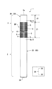
inhaler, the heat that is generated when the flavor
generating source is heated by the heater tends to stay
in the casing, and there is a concern that the influence
of the heat accumulated in the casing may adversely
- 2 -
CA 03031363 2019-01-18
affect the parts, the flavor generating source and the
like in the flavor inhaler.
[0006] The present invention has been made in view of
the above circumstance, and it is an object of the
present invention to provide a heating-type flavor
inhaler in which heat that is generated when the flavor
generating source is electrically heated by the heater is
less likely to stay in the casing.
Solution to Problem
[0007] In the present invention to solve the above
problems, on the casing of the heating-type flavor
inhaler, a bumpy pattern that is made of metal and
facilitates heat dissipation is provided on an outer
circumferential surface of at least a position where a
heater is arranged.
[0008] More specifically, a heating-type flavor
inhaler according to the present invention includes: a
- 3 -
CA 03031363 2019-01-18
casing having a mouthpiece opening and being cylindrical
in overall shape; a flavor generating source provided in
the casing; and a heater, provided in the casing, for
electrically heating the flavor generating source,
wherein a bumpy pattern that is made of metal and
facilitates heat dissipation is provided on an outer
circumferential surface of at least a position of the
casing at which the heater is arranged. In the present
invention, the bumpy pattern may be formed by arranging a
pattern of protrusions on the outer circumferential
surface of the casing, or by arranging a pattern of dent
portions on the outer circumferential surface of the
casing by, for example, cutting and the like.
[0009] Moreover, in the heating-type flavor inhaler
according to the present invention, the heater may be
arranged in a central region in a longitudinal direction
of the casing, in a bumpy-pattern-arranged section where
the bumpy pattern is formed.
- 4 -
CA 03031363 2019-01-18
[0010]
Here, the bumpy pattern may include a plurality of
protrusions aligned on the outer circumferential surface
of the casing.
[0011]
Further, in the heating-type flavor inhaler
according to the present invention, a no-bumpy-pattern-
arranged section where the bumpy pattern is not provided
may be formed over a predetermined section from a
mouthpiece-opening end of the casing in a longitudinal
direction.
[0012]
Here, in the heating-type flavor inhaler according
to the present invention, a height dimension of each of
the protrusions in the bumpy pattern may be larger than a
width dimension of the protrusion.
[0013]
- 5 -
CA 03031363 2019-01-18
Furthermore, in the heating-type flavor inhaler
according to the present invention, each of the
protrusions in the bumpy pattern may have a tapered shape
toward a top portion.
[0014]
Additionally, in the heating-type flavor inhaler
according to the present invention, a heat insulating
material may be provided on a top portion of each of the
protrusions in the bumpy pattern.
Effects of the Invention
[0015] According to the present invention, it is
possible to provide the heating-type flavor inhaler in
which heat that is generated when the flavor generating
source is electrically heated by the heater is less
likely to stay in the casing.
Brief Description of the Drawings
- 6 -
CA 03031363 2019-01-18
[0016]
[Fig. 1] Fig. 1 is an external view of an electronic
cigarette according to Embodiment 1.
[Fig. 2] Fig. 2 is an external view of the electronic
cigarette according to Embodiment 1.
[Fig. 3] Fig. 3 is an internal structural view of the
electronic cigarette according to Embodiment 1.
[Fig. 4A] Fig. 4A is a conceptual view illustrating, in
an exploded manner, the outer circumferential surface of
a casing of the electronic cigarette according to
Embodiment 1.
[Fig. 4B] Fig. 4B is a perspective view of a protrusion
provided in the casing of the electronic cigarette
according to Embodiment 1.
[Fig. 5A] Fig. 5A is a view illustrating a variation of
the shape of a protrusion constituting the bumpy pattern
according to Embodiment 1.
- 7 -
CA 03031363 2019-01-18
[Fig. 5B] Fig. 5B is a view illustrating a variation of
the shape of a protrusion constituting the bumpy pattern
according to Embodiment 1.
[Fig. 6] Fig. 6 is a view illustrating an electronic
cigarette according to Modified Example 1 of Embodiment 1.
[Fig. 7] Fig. 7 is a view illustrating an electronic
cigarette according to Modified Example 2 of Embodiment 1.
[Fig. 8] Fig. 8 is a view illustrating an electronic
cigarette according to Modified Example 3 of Embodiment 1.
Description of Embodiment
[0017] Here, an embodiment of a heating-type flavor
inhaler according to the present invention will be
described based on the drawings. The dimensions,
materials, shapes, relative arrangements, etc. of the
component parts described in the present embodiment are
not intended to limit the technical scope of the
- 8 -
CA 03031363 2019-01-18
invention only to them, unless otherwise specified
particularly.
[0018] [Embodiment 1]
Figs. 1 to 3 are schematic views of an electronic
cigarette 1 as an example of a heating-type flavor
inhaler according to Embodiment 1. Figs. 1 and 2 are
external views of the electronic cigarette 1 according to
Embodiment 1. Fig. 3 is an internal structural view of
the electronic cigarette 1 according to Embodiment 1.
[0019] In the electronic cigarette 1, a main body part
2 and a cartomizer part 3 are freely attachable to and
detachable from each other. Fig. 1 illustrates a state
in which the main body part 2 and the cartomizer part 3
are united. Fig. 2 illustrates a state in which the main
body part 2 and the cartomizer part 3 are separated.
Here, reference numeral 20 is a casing of the main body
part 2 (hereinafter referred to as the "first casing"),
and reference numeral 30 is a casing of the cartomizer
- 9 -
CA 03031363 2019-01-18
part 3 (hereinafter referred to as the "second casing").
Hereinafter, when referring to the first casing 20 and
the second casing 30 collectively, the first casing 20
and the second casing 30 are simply referred to as the
"casing CS". The overall shape of the casing of the
electronic cigarette 1 is a cylindrical shape (rod-like
shape). In the present description, the term "casing"
means a case that houses various parts of the electronic
cigarette 1 and may be referred to as, for example, the
"shell", "housing", or the like.
[0020] A battery 21, an electronic control unit 22, a
suction detection sensor 23, etc. are housed in the first
casing 20 of the main body part 2. Moreover, an LED 24
is provided on one end of the main body part 2. The
battery 21 may be a rechargeable battery such as, for
example, a lithium ion secondary battery. The electronic
control unit 22 is a computer that controls the entire
electronic cigarette 1. The electronic control unit 22
- 10 -
CA 03031363 2019-01-18
may be, for example, a microprocessor having a circuit
board (not illustrated) on which a processor, a memory,
etc. are mounted.
[0021] The first casing 20 is, for example, a
cylindrical shell with a bottom, and the LED 24, the
electronic control unit 22, the battery 21 and the
suction detection sensor 23 are arranged from the bottom
surface 20a side. Provided on the upper-end side of the
first casing 20 is a first engagement part 25 that makes
it possible to freely attach or detach the main body part
2 to or from the cartomizer part 3. Further, on the
upper end of the first casing 20, a first air inlet hole
26, which is a cutout for taking outside air into the
inside, is provided.
[0022] Next, the cartomizer part 3 will be described.
The cartomizer part 3 is an assembly in which a heater
unit and a cartridge section are united. The second
casing 30 of the cartomizer part 3 is, for example, a
- 11 -
CA 03031363 2019-01-18
cylindrical shell with a bottom, and a mouthpiece opening
31, which is a suction opening, is made at the center of
an upper end surface 30a. The cartomizer part 3 also
functions as a mouthpiece, and a user can inhale an
aerosol generated in the cartomizer part 3 from the
mouthpiece opening 31 by holding the upper-end side of
the second casing 30 in his or her mouth and sucking.
The mouthpiece-opening end side of the cartomizer part 3
may have a tapered shape toward the upper-end side to
allow the user to easily hold the cartomizer part 3 in
his or her mouth.
[0023] The lower-end side of the second casing 30 of
the cartomizer part 3 is provided with a second
engagement part 32 that makes it possible to freely
attach or detach the cartomizer part 3 to or from the
main body part 2. The second engagement part 32 of the
cartomizer part 3 can be engaged with and disengaged from
the first engagement part 25 of the main body part 2.
- 12 -
CA 03031363 2019-01-18
Means for engaging the first engagement part 25 of the
main body part 2 and the second engagement part 32 of the
cartomizer part 3 is not particularly limited, and a
screw connection method is adopted in the present
embodiment. However, instead of the screw connection
method, it is possible to use known connection means such
as connection through a sleeve member, for example,
fitting connection and the like. Furthermore, as
illustrated in Fig. 2, a second air inlet hole 37, which
is a cutout for taking outside air into the inside, is
provided in the lower end portion of the second casing 30.
In a state in which the cartomizer part 3 is attached to
the main body part 2, the second air inlet hole 37
communicates with the first air inlet hole 26 of the main
body part 2, and an air inlet Al is formed by a
combination of the air inlet holes 37 and 26.
[0024] Next, the internal structure of the cartomizer
part 3 will be described in detail. The inside of the
- 13 -
CA 03031363 2019-01-18
second casing 30 of the oartomizer part 3 has a double
cylinder structure, and the inner space of the second
casing 30 is divided into a cartridge section 34 for
storing an aerosol-generating liquid, and an internal
passage 39 by a cylindrical partition wall 33. In the
cartridge section 34, a liquid supply member 38, such as
cotton fiber impregnated with the aerosol-generating
liquid, is arranged. The aerosol-generating liquid is a
liquid that generates an aerosol by being heated, and a
polyol containing a flavoring is adopted in the present
embodiment, although the aerosol-generating liquid is not
particularly limited. For example, the aerosol-
generating liquid may be a mixed solution of glycerin,
propylene glycol, nicotine solution, water, flavoring,
etc.
[0025] Reference numeral 35 is
a wick that directly or
indirectly sucks up and holds the aerosol-generating
liquid stored in the cartridge section 34. The wick 35
- 14 -
CA 03031363 2019-01-18
may be, for example, a twisted glass fiber yarn. The
wick 35 has a capillary structure, and can directly sucks
up the aerosol-generating liquid stored in the cartridge
section 34, or indirectly suck up the aerosol-generating
liquid through the liquid supply member 38 made of cotton
fiber impregnated with the aerosol-generating liquid
liquid by utilizing a capillary phenomenon, and hold the
aerosol-generating. The wick 35 is held by the partition
wall 33 in a state of being inserted through a pair of
holding holes (not illustrated) provided in the partition
wall 33. As illustrated in Fig. 3, the wick 35 is placed
across a transverse section of the internal passage 39,
and is arranged in such a manner that both ends of the
wick 35 extend to the inside of the cartridge section 34
and in contact with the liquid supply member 38 made of
cotton fiber.
[0026] Moreover, as
illustrated in Fig. 3, an electric
heater 36 having an electric heating coil is wound around
- 15 -
CA 03031363 2019-01-18
the wick 35. The wick 35 also functions as a core member
that supports the electric heating coil of the electric
heater 36. The electric heater 36 surrounds at least
partially the center portion of the wick 35 in the
longitudinal direction, and when the electric heater 36
is activated by conducting electricity, the wick 35 is
heated and consequently the aerosol-generating liquid
held in the wick 35 evaporates.
[0027] Here, the electronic control unit 22 and the
battery 21 are connected through electric wiring, and
conducting electricity from the battery 21 to the
electric heater 36 is controlled by the electronic
control unit 22. Here, the electronic cigarette 1 can
detect a vaping request from the user by detecting
sucking (puff) of the mouthpiece opening (suction
opening) 31 by the user with the suction detection sensor
23 arranged in the main body part 2. For example, when
the user sucks the mouthpiece opening 31, outside air is
- 16 -
CA 03031363 2019-01-18
taken into the inside of the casing CS from the air inlet
Al. Based on a pressure change inside the casing CS at
this time, the suction detection sensor 23 can detect the
sucking of the mouthpiece opening 31 by the user. When
the suction detection sensor 23 detects the sucking of
the mouthpiece opening 31 by the user, the electronic
control unit 22 supplies power from the battery 21 to the
electric heater 36 and heats the wick 35, thereby
evaporating the aerosol-generating liquid.
[0028] As the suction detection sensor 23, it may be
possible to use a pressure sensitive sensor or a thermal-
type flow meter (MEWS flow sensor or the like) that
detects a negative pressure produced due to the sucking
by the user. Instead of the suction detection sensor 23,
a vaping switch (not illustrated) for accepting a
manipulation from the user may be provided in the casing
CS of the electronic cigarette 1. In this case, the
vaping switch is connected to the electronic control unit
- 17 -
CA 03031363 2019-01-18
22 through electric wiring, and the electronic control
unit 22 detects turning on of the vaping switch. When
the vaping switch is on, the electronic control unit 22
can evaporate the aerosol-generating liquid by conducting
electricity to the electric heater 36 from the battery 21.
[0029] As illustrated in Fig. 2, the second air inlet
hole 37, which is a cutout for taking outside air into
the inside, is provided in the lower end portion of the
second casing 30. In a state in which the cartomizer
part 3 is attached to the main body part 2, the second
air inlet hole 37 communicates with the first air inlet
hole 26 of the main body part 2, and the air inlet Al is
formed by a combination of these air inlet holes.
[0030] As described above, when the sucking of the
mouthpiece opening 31 by the user is detected, the
electronic cigarette 1 heats the wick 35 by conducting
electricity to the electric heater 36, and evaporates
(vaporizes) the aerosol-generating liquid held in the
- 18 -
CA 03031363 2019-01-18
wick 35. In addition, the air flowing into the casing
from the air inlet Al when the user sucks the mouthpiece
opening 31 is guided to an inner end of the internal
passage 39 in the cartomizer part 3. The mouthpiece
opening 31 is provided at an outer end of the internal
passage 39, and the air flowing into the internal passage
39 flows through the internal passage 39 toward the
mouthpiece opening 31. Here, as illustrated in Fig. 3,
in the course of the internal passage 39, the wick 35
that holds the electric heater 36 is placed across the
internal passage 39. When the user sucks the mouthpiece
opening 31, the aerosol-generating liquid which is
evaporated (vaporized) by heating the wick 35 with the
electric heater 36 is mixed with the air flowing in the
internal passage 39, thereby generating an aerosol. Thus,
the aerosol generated in the internal passage 39 is
guided to the mouthpiece opening 31 through the internal
- 19 -
CA 03031363 2019-01-18
passage 39, and the user can inhale the aerosol from the
mouthpiece opening 31.
[0031] In the electronic cigarette 1 configured as
described above, since the aerosol-generating liquid,
which is a flavor generating source held in the wick 35,
is heated with the electric heater 36, a large amount of
heat may be generated by the electric heater 36. Here,
if a large amount of heat is kept inside the casing CS,
there is a concern that the respective components housed
in the casing CS, for example, the electronic control
unit 22 and the aerosol-generating liquid stored in the
cartridge section 34 may be affected. Therefore, the
casing CS of the electronic cigarette 1 according to the
present embodiment employs a structure that facilitates
release of heat generated by the electric heater 36 to
the outside.
[0032] Hereinafter, the heat dissipation structure of
the electronic cigarette 1 will be described. As
- 20 -
CA 03031363 2019-01-18
illustrated in Figs. 1 to 3, on the outer circumferential
surface of the casing CS of the electronic cigarette 1, a
bumpy pattern BP made of metal which facilitates heat
dissipation is provided. The bumpy pattern BP includes a
plurality of protrusions 5 regularly aligned on the outer
circumferential surface of the casing CS. Fig. 4A is a
conceptual view illustrating, in an exploded manner, the
outer circumferential surface of the casing CS of the
electronic cigarette 1 according to Embodiment 1. Fig.
4B is a perspective view of the protrusion 5 provided on
the casing CS of the electronic cigarette 1 according to
Embodiment 1. In the present embodiment, each of the
protrusions 5 constituting the bumpy pattern BP has a
quadrangular prism shape as illustrated in Fig. 4B, but
the protrusions 5 may have other shapes, such as
variations illustrated as examples in Figs. 5A and 5B.
Fig. 5A illustrates an example of the protrusion 5 having
- 21
CA 03031363 2019-01-18
a columnar shape. Fig. 58 illustrates an example of the
protrusion 5 having a bell shape (bowl shape).
[0033] Reference numeral 6
illustrated in Figs. 1 to 3
indicates an outer circumferential wall of the casing CS.
The plurality of protrusions 5 constituting the bumpy
pattern BP are formed in a protruding manner on an outer
circumferential surface 6a of the outer circumferential
wall 6 of the casing CS. As is apparent from Figs. 1 to
3, the metal bumpy pattern BP is provided on the outer
circumferential surface 6a of the casing CS at least at a
position (range) where the electric heater 36 is placed.
In short, in the electronic cigarette 1 according to the
present embodiment, the metal bumpy pattern BP is
arranged on the outer circumferential surface 6a of the
casing CS to cover the side of the electric heater 36.
Here, by providing the bumpy pattern BP on the outer
circumferential surface 6a of the casing CS, it is
possible to appropriately increase the surface area, that
- 22 -
CA 03031363 2019-01-18
is, the heat dissipation area of the casing CS. Further,
by making the bumpy pattern BP of a metal having
excellent heat conductivity, it is possible to facilitate
heat dissipation by the bumpy pattern BP.
[0034] As a result, heat is
less likely to stay in the
casing CS of the electronic cigarette 1, and it is
possible to reduce the adverse effect on the respective
components housed in the casing CS, for example, the
electronic control unit 22 and the aerosol-generating
liquid stored in the cartridge section 34. Furthermore,
according to the present embodiment, since the bumpy
pattern BP is formed by aligning the plurality of
protrusions 5 on the outer circumferential surface 6a of
the casing CS, it is possible not only to appropriately
dissipate the heat inside the casing CS, but also to
reduce the contact area between the fingers of the user
holding the electronic cigarette 1 and the outer
circumferential surface 6a of the casing CS.
- 23 -
CA 03031363 2019-01-18
Consequently, the heat is less likely transferred to the
fingers of the user holding the electronic cigarette 1,
thereby producing the effect of less likely giving an
unpleasant feeling to the user.
[0035] Here, in the longitudinal direction of the
casing CS, a section where the bumpy pattern BP is formed
is referred to as a "bumpy-pattern-arranged section Zl"
(see Fig. 1). In the present embodiment, the electric
heater 36 is arranged in the central portion, in the
longitudinal direction, in the bumpy-pattern-arranged
section Zl. Accordingly, it is possible to arrange the
bumpy pattern BP in a well-balanced manner so that a
position where the temperature is likely the highest is
the center in the longitudinal direction of the
electronic cigarette 1 (casing CS), thereby making it
possible to efficiently dissipate the heat generated by
the electric heater 36 to the outside (the atmosphere).
Thus, it is possible to make it harder for the heat to
- 24 -
=
CA 03031363 2019-01-18
stay in the casing CS of the electronic cigarette 1. The
material that farms the bumpy pattern BP (protrusions 5)
is not particularly limited as long as the material is
made of metal, and may be, for example, stainless steel,
aluminum, or the like.
[0036] Here, the rate of increase of the heat
dissipation area (surface area) by providing the outer
circumferential surface 6a of the casing CS with the
bumpy pattern BP will be calculated. As an example of
conditions, if the diameter of the electronic cigarette 1
(the outer diameter of the outer circumferential wall 6
of the casing CS) is 10 mm, the bumpy-pattern-arranged
section Z1 is 30 mm, the shape of the protrusion 5 is a
1-mm cube and adjacent protrusions 5 are separated from
each other by 1 mm, the rate of increase of the heat
dissipation area (surface area) is about 202%. In the
present embodiment, from the viewpoint of heat
dissipation, the rate of increase of the surface area of
- 25 -
=
CA 03031363 2019-01-18
the casing CS by providing the outer circumferential
surface 6a of the casing CS with the bumpy pattern BP
(protrusions 5) is preferably 20% or more.
[0037] Here, in the casing CS of the electronic
cigarette 1, an end portion where the mouthpiece opening
31 is provided is referred to as a "mouthpiece-opening
end 3a". In the electronic cigarette 1 according to the
present embodiment, a no-bumpy-pattern-arranged section
Z2 (see Fig. 1) in which the bumpy pattern BP is not
provided is formed over a predetermined section from the
mouthpiece-opening end 3a in the longitudinal direction
of the casing CS. Thus, by not providing the bumpy
pattern BP in a region on the mouthpiece-opening end 3a
side of the casing CS, when the user holds in his or her
mouth the mouthpiece opening 31 of the electronic
cigarette 1, it is possible to prevent the mouth from
touching the metal bumpy pattern BP arranged on the outer
circumferential surface 6a of the bumpy-pattern-arranged
- 26 -
=
CA 03031363 2019-01-18
section 21 of the casing CS. The length of the no-bumpy-
pattern-arranged section Z2 is not particularly limited,
but is preferably 20 mm or more. That is, by not
providing the bumpy pattern BP in the section of at least
20 mm from the mouthpiece-opening end 3a of the casing CS,
it is possible to effectively prevent the lips of the
user from touching the bumpy pattern BP when the
electronic cigarette 1 is held in the mouth.
[0038] Moreover, in the electronic cigarette 1 of the
present embodiment, as illustrated in Figs. 4 and 5, a
height dimension HS of the protrusion 5 of the bumpy
pattern BP is preferably larger than a width dimension WS.
Accordingly, when the height dimension HS is made
relatively larger than the width dimension WS of the
protrusion 5, the surface area (heat dissipation area) of
the casing CS can be further increased by providing the
outer circumferential surface 6a of the casing CS with
the bumpy pattern BP. Consequently, it is possible to
- 27 -
CA 03031363 2019-01-18
more easily dissipate the heat in the casing CS of the
electronic cigarette 1 to the outside.
[0039] Further, as described above, by making the
height dimension HS larger compared to the width
dimension WS of the protrusion 5 of the bumpy pattern BP,
the area of a side surface (side portion) 5b (see Figs. 4
and 5) of the protrusion 5 (hereinafter referred to as
the "side-portion area SS") can be relatively larger than
the area of a top surface (top portion) 5a (see Figs. 4
and 5) of the protrusion 5 (hereinafter referred to as
the "top-portion area ST"). That is, it is possible to
increase the ratio of the side-portion area SS to the
entire surface area of the protrusion 5. Accordingly,
when the user holds the electronic cigarette 1, the
contact area between the fingers and the protrusions 5
can be smaller, thereby making it harder for the heat of
the protrusions 5 from being transferred to the fingers
of the user. Furthermore, by increasing the ratio of the
- 28 -
CA 03031363 2019-01-18
side-portion area SS to the entire surface area of the
protrusion 5 as described above, it is possible to
prioritize heat dissipation from the side surface 5b of
the protrusion 5. Consequently, the temperature of the
top surface 5a of the protrusion 5 is hard to be higher,
and it is possible to make it harder to give an
unpleasant feeling to the user who holds the electronic
cigarette 1.
[0040] In addition, as
illustrated in Fig. 5B, if each
of the protrusions 5 of the bumpy pattern BP has a
tapered shape toward the top surface (top portion) 5a, it
is possible to further reduce the contact area between
the fingers of the user and the protrusions 5 when the
user holds the electronic cigarette 1. Therefore, it is
possible to make it harder for the heat of the
protrusions 5 to be transferred to the fingers of the
user.
- 29 -
[0041] In the electronic cigarette 1 according to the
present embodiment, a heat insulating material 7 is
preferably provided on the top surface (top portion) 5a
of each protrusion 5 constituting the bumpy pattern BP
(see Fig. 5A). The heat insulating material 7 provided
on the top surface 5a of each protrusion 5 constituting
the bumpy pattern BP may be, for example, a heat
insulating paint (heat insulating coating material) or
the like. By applying a heat insulating paint or the
like to the top surface 5a of the protrusion 5, the heat
insulating properties of the top surface 5a of the
protrusion 5 can be enhanced. Accordingly, it is
possible to positively prevent the top surface 5a from
heating up while prioritizing release of the heat
generated by the electric heater 36 in the casing CS from
the side surface 5b of the protrusion 5 to the outside.
Therefore, the heat of the protrusions 5 is less likely
transferred to the fingers of the user, and it is
- 30 -
Date Recue/Date Received 2021-03-04
CA 03031363 2019-01-18
possible to appropriately prevent the heat from giving an
unpleasant feeling to the user. The type of the heat
insulating paint for coating the top surface 5a of the
protrusion 5 is not particularly limited, but an example
is a paint produced by making ceramics having high heat
insulating properties into an emulsion (emulsifying and
mixing of fine particles).
[0042] In the electronic cigarette 1 according to the
present embodiment, the plurality of protrusions 5 are
regularly aligned at constant intervals on the outer
circumferential surface 6a of the casing CS, but the
present invention is not limited by this. For example,
the interval between the plurality of protrusions 5
aligned on the outer circumferential surface 6a of the
casing CS may not be constant. Fig. 6 is a view
illustrating an electronic cigarette lA according to
Modified Example 1 of Embodiment 1. The electronic
cigarette lA illustrated in Fig. 6 is the same as the
- 31 -
CA 03031363 2019-01-18
aspect illustrated in Figs. 1 to 3 in that the electric
heating coil of the electric heater 36 is arranged in a
central region Zla of the bumpy-pattern-arranged section
Zl, but the interval (pitch) between the protrusions 5 is
changed in the central region Zla of the bumpy-pattern-
arranged section Zl and end regions Zlb located on both
sides of the central region Zla.
[0043] In the example illustrated in Fig. 6, the
interval between the protrusions 5 in the central region
Zla of the bumpy-pattern-arranged section Z1 is set
smaller than the interval between the protrusions 5 in
the end regions Zlb. Consequently, in the bumpy-pattern-
arranged section Zl of the casing CS, it is possible to
arrange the protrusions 5 more densely in the central
region Zla than in the end regions Zlb. Accordingly,
since the arrangement density of the protrusions 5 can be
the highest in the central region Zla corresponding to
the position of the electric heater 36 in the bumpy-
- 32 -
CA 03031363 2019-01-18
pattern-arranged section Zl of the casing CS, heat from
the electric heater 36 can be more appropriately
dissipated to the outside.
[0044] While the preferred embodiment of the present
invention has been described above, it is apparent to
those skilled in the art that various modifications,
improvements, combinations and the like can be made for
the heating-type flavor inhaler according to the present
invention. For example, in the above-described
electronic cigarette 1 of Embodiment 1, the aerosol-
generating liquid is stored in a manner in which the
aerosol-generating liquid is impregnated into the liquid
supply member 38 made of cotton fiber or the like
arranged in the cartridge section 34, but it is also
possible to adopt a tank system in which the aerosol-
generating liquid is stored in a so-called liquid tank,
or it is possible to provide an atomizer that evaporates
the aerosol-generating liquid and the liquid tank as
- 33 -
CA 03031363 2019-01-18
separate units. In the above-described embodiment, the
example in which the bumpy pattern BP is formed by
providing the protrusions 5 in a protruded pattern on the
outer circumferential surface 6a of the outer
circumferential wall 6 of the casing CS of the electronic
cigarette 1 is described, but the present invention is
not limited by this. For example, the bumpy pattern BP
may be formed by providing a pattern of dent portions on
the outer circumferential surface 6a of the outer
circumferential wall 6 of the casing CS by, for example,
cutting and the like. In this case, for example, a
plurality of dent portions may be provided at constant
intervals on the outer circumferential surface 6a of the
casing CS. At that time, the protrusions 5 are formed
between the adjacent dent portions, and the bumpy pattern
BP is formed by a combination of the dent portions and
the protrusions 5.
- 34 -
CA 03031363 2019-01-18
[0045] Further, for example, like an electronic
cigarette 1B according to Modified Example 2 illustrated
in Fig. 7, a tobacco cartridge 8 that contains tobacco
leaves may be arranged at a rear stage of the cartridge
section 34 of the cartomizer part 3. Fig. 7 partially
illustrates only the cartomizer part 3 side of the
electronic cigarette 1B. A front end face 8a and a rear
end face 8b of the tobacco cartridge 8 are configured to
allow passage of an aerosol generated in the cartomizer
part 3. The aerosol generated in the cartomizer part 3
flows into the tobacco cartridge 8 from the front end
face 8a. The user can inhale from the rear end face 8b
the aerosol that has received a tobacco component and a
flavoring component when the aerosol passes through the
inside of the tobacco cartridge 8. In this type of
electronic cigarette 1B, if the same heat dissipation
structure as in Embodiment 1 is adopted, it is also
- 35 -
CA 03031363 2019-01-18
possible to appropriately dissipate the heat generated by
the electric heater 36 to the outside.
[0046] Moreover, the present invention is also
applicable to an electronic cigarette as illustrated in
Fig. 8. Fig. 8 is a view illustrating an electronic
cigarette 10 according to Modified Example 3. Fig. 8 is
a longitudinal sectional view when the cylindrical
electronic cigarette 10 is cut in a longitudinal
direction thereof. The electronic cigarette 10 has a
battery 101, a pod 103 that contains a tobacco filler 102,
an electric heater 104, and a mouthpiece 105. By filling
the pod 103 with the tobacco filler 102 and heating the
tobacco filler 102 in the pod 103 with the electric
heater 104, an aerosol is generated and can be inhaled
from the mouthpiece 105. In the example illustrated in
Fig. 8, the bumpy pattern BP including a plurality of
protrusions 5 made of metal is also provided on the outer
circumferential surface 6a of a position of the casing CS
- 36 -
at which the electric heater 104 is arranged. Thus, heat
generated by the electric heater 104 can be appropriately
dissipated to the outside.
Reference Signs List
[0047]
1 Electronic Cigarette (Heating-Type Flavor Inhaler)
2 Main body part
3 Cartcmizer part
Protrusion
20 First casing
21 Battery
22 Electronic control unit
23 Suction detection sensor
24 LED
30 Second casing
31 Mouthpiece opening
32 Second engagement part
- 37 -
Date Recue/Date Received 2021-03-04
CA 03031363 2019-01-18
34 Cartridge section
35 Wick
36 Electric heater
38 Liquid supply member
39 Internal passage
CS Casing
BP Bumpy pattern
- 38 -