Note: Descriptions are shown in the official language in which they were submitted.
Description
Wireless Electric Energy Transmission Magnetic Path Coupling Mechanism
I. Technical Field
The present invention relates to the technical field of wireless electric
energy
transmission, particularly to a new magnetic path coupling mechanism for
wireless
electric energy transmission.
Background Art
Wireless electric energy transmission technology is a fire-new electric power
access
mode that realizes the transmission of electric power from a power source
device to a
power-receiving device under a condition of complete electrical isolation by
means of
a spatial invisible soft medium (e.g., magnetic field, electric field, laser,
microwave,
etc.). The technology fundamentally eliminates the problems of device wear,
poor
contact and touch spark, etc. caused by the conventional "socket + connector"
power
supply mode, and is a clean, safe and flexible new power supply mode. It has
been
evaluated by Technology Review in USA as one of the ten major scientific
research
directions in the future.
Wherein, a magnetic path coupling mechanism for wireless electric energy
transmission is a key essential difference between the wireless electric
energy
transmission technology and the conventional wire electric energy transmission
mode,
and the performance thereof characterizes the quality of the wireless electric
energy
transmission system. Therefore, it is very important to make research on the
magnetic
path coupling mechanism for wireless electric energy transmission. The key
index for
measuring the performance of the magnetic path coupling mechanism for wireless
electric energy transmission is the coupling coefficient k, which can measure
the
coupling degree of the magnetic path mechanism. In practice, the coupling
coefficient
k is usually in the range of 0.01 to 0.5. The higher the k value is, the
closer the
coupling of the magnetic path mechanism is, and the higher the efficiency of
the
magnetic path coupling mechanism is. Owing to a fact that there is a large air
gap
between the primary side energy emission cushion and the secondary side energy
collection cushion of the magnetic path coupling mechanism for wireless
electric
energy transmission in order to realize non-contact, it is difficult to align
the
secondary side energy collection cushion with the primary side energy emission
cushion accurately, and relative position offset between the primary side
energy
emission cushion and the secondary side energy collection cushion is
inevitable.
Therefore, a magnetic path coupling mechanism with a wider offset tolerance
range is
more practical. A variety of possible offset positions may exist between the
primary
side energy emission cushion and the secondary side energy collection cushion.
For
the convenience of research, usually three offset directions, i.e., two
orthogonal
horizontal directions coplanar with the secondary side energy collection
cushion and a
= =
Date Recue/Date Received 2020-05-08
CA 03031438 2019-01-21
more practical. A variety of possible offset positions may exist between the
primary side
energy emission cushion and the secondary side energy collection cushion. For
the
convenience of research, usually three offset directions, i.e., two orthogonal
horizontal
directions coplanar with the secondary side energy collection cushion and a
direction of
rotation around the central axis thereof, are selected, in order to study the
anti-offset
characteristics of the magnetic path coupling mechanism. Any offset condition
of the
magnetic path coupling mechanism can be achieved by superimposing the above
three
offset directions. In particular, a greater coupling coefficient k can provide
a wider offset
tolerance range.
A great many of researches have been made on magnetic path coupling mechanisms
for
wireless electric energy transmission, and in relevant techniques, a DD-type
magnetic
path coupling mechanism proposed by the University of Auckland has been
applied
widely owing to its excellent performance. The DD-type magnetic path coupling
mechanism is developed from a magnetron-based magnetic path coupling
mechanism.
However, compared with the latter, the former only provides a flux path on one
side in
the air, while the flux path on the other side forms a closed path via the
associated ferrite
strip. Therefore, the DD-type magnetic path coupling mechanism has a greater
coupling
coefficient with the same gap. Besides, the DD-type magnetic path coupling
mechanism
has a better offset tolerance in the direction perpendicular to the ferrite
strip thereof, but
has a poorer offset tolerance in the direction parallel to the ferrite strip
thereof and the
direction of rotation around the center of the mechanism.
III. Contents of the Invention
Object of the Invention: the object of the present invention is to provide a
new magnetic
path coupling mechanism for wireless electric energy transmission, which not
only has a
higher coupling coefficient, but also provides wider offset tolerance ranges
in three
directions, i.e., two orthogonal horizontal directions and a direction of
rotation around the
central axis of the mechanism.
Technical Solution: to attain the above-mentioned technical effects, the
present invention
provides the following technical solution:
A new magnetic path coupling mechanism for wireless electric energy
transmission,
comprising: a primary side energy emission cushion and a secondary side energy
collection cushion, which are arranged opposite to each other and in parallel
with each
other; both the primary side energy emission cushion and the secondary side
energy
collection cushion are of a two-layer structure, wherein, one layer is a coil
layer formed
by winding Litz wires, and the other layer is a magnetic core layer; both the
coil layer and
the magnetic core layer are of a centrosymmetric structure; wherein, the coil
layer
consists of two identical rectangular coils laminated orthogonally, and the
magnetic core
= 2 =
CA 03031438 2019-01-21
layer is a Sudoku-shaped grid layer consisting of 8 ferrite strips with the
same length; the
coil layer of the primary side energy emission cushion and the coil layer of
the secondary
side energy collection cushion are opposite to each other, and the opposite
surfaces of the
primary side energy emission cushion and the secondary side energy collection
cushion
are in mirror symmetry.
Furthermore, the length of the ferrite strip is equal to the length of the
rectangular coil.
Furthermore, among the 4 ferrite strips in the middle of the magnetic core
layer, the
positions of any two ferrite strips parallel to each other meet the following
condition:
w=0.2a
wherein, w is the outer margin between two ferrite strips parallel to each
other; a is the
length of the rectangular coil.
Furthermore, the ratio of the width to the length of the rectangular coil is
0.7.
Benefits: compared with the prior art, the present invention has the following
advantages:
The new magnetic path coupling mechanism for wireless electric energy
transmission
according to the present invention is a magnetic path coupling structure with
outstanding
performance. Compared with relevant techniques, the new magnetic path coupling
mechanism for wireless electric energy transmission according to the present
invention
has a higher coupling coefficient, and can provide wider offset tolerance
ranges in three
directions at the same time, i.e., two orthogonal horizontal directions and a
direction of
rotation around the central axis of the mechanism. The present invention
provides a more
diversified option of magnetic path coupling mechanism for selection of
magnetic path
coupling mechanism for wireless electric energy transmission system.
IV. Brief Description of Drawings
Fig. 1 is a schematic structural view of example 1;
Fig. 2 is a schematic view of the winding pattern and key parameters of the
primary side
energy emission cushion according to example I;
Fig. 3 shows the Model diagram of magnetic path coupling mechanism in the
prior art;
Fig. 4 shows the comparison diagram of the air gap tolerance characteristic
between a
DD-type magnetic path coupling mechanism and the cross-type magnetic path
coupling
mechanism according to example 1 under the same conditions;
Fig. 5 shows the comparison diagram of the central rotation angle tolerance
characteristic
between a DD-type magnetic path coupling mechanism and the cross-type magnetic
path
coupling mechanism according to example 1 under the same conditions;
= 3 =
CA 03031438 2019-01-21
Fig. 6 shows the comparison diagram of the horizontal offset tolerance
characteristic
between a DD-type magnetic path coupling mechanism and the cross-type magnetic
path
coupling mechanism according to example 1 under the same conditions;
Fig. 7 shows schematic structural views of ferrite core layer of the cross-
type magnetic
path coupling mechanism according to example 1 in five different schemes;
Fig. 8 shows the comparison diagram of relation curves between coupling
coefficient k
and c of the cross-type magnetic path coupling mechanism according to example
1 for
different values of a and q=0.5, under the conditions of air gap=200 mm, n=10
turns;
Fig. 9 shows the comparison diagram of relation curves between coupling
coefficient k
and c of the cross-type magnetic path coupling mechanism according to example
1 for
different values of q and a=600 mm, under the conditions of air gap=200 mm,
n=10
turns;
Fig. 10 is a schematic diagram illustrating the ferrite magnetic core layer
structure and
parameters according to example 2;
Fig. 11 shows the diagram of relation curves of coupling coefficient k and q
of the
cross-type magnetic path coupling mechanism according to example 2 for
different
values of a, under the conditions of n=10 turns and air gap=200mm;
Fig. 12 shows the diagram of relation curves of coupling coefficient k and q
of the
cross-type magnetic path coupling mechanism according to example 2 for
different
values of air gap, under the conditions of n=10 turns and a=600mm;
Fig. 13 shows the diagram of curves of k vs. c of the cross-type magnetic path
coupling
mechanism according to example 2 in 30 cases when the value of q is changed
from 0.5
to 1 in step of 0.01 and the number of turns of the rectangular coils is
changed from 10
turns to 30 turns in step of 10 under the conditions of a=600 mm and air
gap=200 mm;
Fig. 14 shows the diagram of curves of k vs. q when the optimal ferrite
magnetic core
layer structure shown in Fig. 16 is used in three cases where the number of
turns n of the
rectangular coil is 10, 20 and 30 respectively under the conditions of a=600
and air
gap=200 mm;
Fig. 15 is a structural diagram of example 3.
In the figures: 101 - first coil layer; 102 - first magnetic core layer; 201 -
second coil
layer; 203 - second magnetic core layer.
V. Embodiments
Hereunder the present invention will be further detailed with reference to the
= 4 =
CA 03031438 2019-01-21
accompanying drawings.
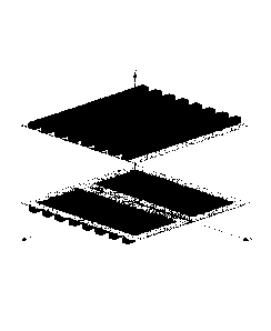
Example 1: Fig. 1 is a structural diagram of example 1 of the present
invention. As shown
in Fig. 1, the magnetic path coupling mechanism for wireless electric energy
transmission
comprises: a primary side energy emission cushion and a secondary side energy
collection cushion; wherein, the primary side energy emission cushion
comprises a first
coil layer 101 and a first magnetic core layer 102, wherein the first coil
layer 101 is
disposed above the first magnetic core layer 102; the secondary side energy
collection
cushion comprises a second coil layer 201 and a second magnetic core layer
202, wherein
the second coil layer 202 is disposed below the second magnetic core layer
202.
Both the first coil 101 and the second coil 201 consist of two identical
rectangular coils
laminated orthogonally. Both of the rectangular coils are wound from Litz
wires.
Both the first magnetic core layer 102 and the second magnetic core layer 202
consist of
8 ferrite strips intersecting each other in longitudinal and transverse
directions, and the
first magnetic core layer 102 and the second magnetic core layer 202 are
entirely
centrally symmetric.
The outer edge length of the first/second magnetic core layers 102/202 is
equal to the
length of the first/second coils 101/201.
In the new magnetic path coupling mechanism for wireless electric energy
transmission
according to the example 1, the primary side energy emission cushion has the
same
structure and the same winding pattern with the secondary side energy
collection cushion.
For example, the winding pattern and key parameters of the primary side energy
emission
cushion are shown in Fig. 2: it consists of a first coil 101 and a first
magnetic core layer
102, and the overall structure is in central symmetry. The first coil 101
consists of two
identical rectangular coils laminated orthogonally. Therefore, the magnetic
path coupling
mechanism according to the present invention is also referred to as a cross-
type magnetic
path coupling mechanism, and the winding pattern thereof is indicated by the
arrows in
Fig. 2. For the convenience of further describing an optimal composition of
the magnetic
path coupling mechanism, the side length of the ferrite magnetic core layer
and the length
of the rectangular coils are defined as a, the width of the rectangular coils
is defined as b,
the number of turns is defined as n, the ferrite strips of the magnetic core
layer are Mg-Zn
ferrite strips with 30 mm width and 20 mm thickness, the outer margin of the
middle
ferrite strips is defined as w, the ratio of b to a is defined as q, and the
ratio of w to a is
defined as c.
Fig. 3 shows a common magnetic path coupling mechanism with good performance
in
the prior art, which is usually referred to as a DD-type magnetic path
coupling
mechanism. To compare the performance of the cross-type magnetic path coupling
= 5 =
CA 03031438 2019-01-21
mechanism according to the example 1 with the performance of the DD-type
magnetic
path coupling mechanism, the cross-type magnetic path coupling mechanism with
the
same dimensions (600* 600 mm), the same Litz wire length (65.6m) and the same
number
of turns of rectangular coils (10 turns) as the DD-type magnetic path coupling
mechanism
shown in Fig. 3 is manufactured, as shown in Fig. 1. In Fig. 3, the DD-type
magnetic path
coupling mechanism uses a ferrite material in volume of 5,760cm3, and has a
coupling
coefficient of 0.21 with 200 mm air gap; in contrast, the cross-type magnetic
path
coupling mechanism only uses a ferrite material in volume of 5,184cm3 but has
a
coupling coefficient as high as 0.2439 with 200 mm air gap.
Figs. 4-6 show further comparison of offset tolerance between the cross-type
magnetic
path coupling mechanism and the DD-type magnetic path coupling mechanism under
the
above-mentioned conditions, wherein, Figs. 4, 5 and 6 respectively show
comparison
diagrams of coupling coefficient vs. air gap, central rotation angle and
horizontal offset
between the two magnetic path coupling mechanisms.
The curve (1) and curve (2) in Fig. 4 are relation curves of coupling
coefficient k vs. air
gap of the cross-type magnetic path coupling mechanism and the DD-type
magnetic path
coupling mechanism respectively. It can be seen clearly that the cross-type
magnetic path
coupling mechanism is more advantageous than the DD-type magnetic path
coupling
mechanism within an air gap range of 100-250 mm.
The curve (3) and curve (4) in Fig. 5 are relation curves of coupling
coefficient k vs.
central rotation angle of the cross-type magnetic path coupling mechanism and
the
DD-type magnetic path coupling mechanism with air gap of 200 mm. It can be
seen from
the figure: the coupling coefficient k of the DD-type magnetic path coupling
mechanism
fluctuates severely as the central rotation angle increases; particularly, the
value of k is
maximum at 0 and 180 angles, but is close to 0 at 90 and 270 angles, which
brings
severe disturbances to stable operation of the entire wireless electric energy
transmission
system. In contrast, the coupling coefficient of the cross-type magnetic path
coupling
mechanism essentially remains unchanged and the stable value thereof is
greater than the
coupling coefficient of the DD-type magnetic path coupling mechanism when a
central
rotation offset occurs.
The curve (5) in Fig. 6 is a coupling coefficient curve of the cross-type
magnetic path
coupling mechanism with horizontal offset in the cross or y direction. Since
the
cross-type magnetic path coupling mechanism is in central symmetry, it has the
same
horizontal offset tolerance characteristic in the cross or y direction, so
there is only one
curve (5) in Fig. 6. In contrast, for the DD-type magnetic path coupling
mechanism, since
the horizontal offset tolerance characteristics in the cross direction and y
direction are
different from each other, the horizontal offset tolerance characteristics are
illustrate by
= 6 =
CA 03031438 2019-01-21
curves (6) and (7) respectively. It can be seen from the figure: the offset
tolerance
characteristic of the DD-type magnetic path coupling mechanism in the cross
direction is
poorer than the offset tolerance characteristic in the y direction; moreover,
a blind spot
(spot with k=0) occurs at 220 mm offset in the cross direction. The horizontal
offset
tolerance characteristic of the cross-type magnetic path coupling mechanism in
the cross
or y direction is superior to the offset tolerance characteristic of the DD-
type magnetic
path coupling mechanism in the cross direction; the coupling coefficient of
the cross-type
magnetic path coupling mechanism is greater than that of the DD-type magnetic
path
coupling mechanism in case that the offset in the y direction is 0-135 mm; the
coupling
coefficient of the DD-type magnetic path coupling mechanism is greater than
that of the
cross-type magnetic path coupling mechanism in case that the offset in the y
direction is
greater than 135 mm.
In summary, the cross-type magnetic path coupling mechanism according to the
present
invention is a magnetic path coupling structure with outstanding performance.
Compared
with relevant techniques in the prior art, it has a higher coupling
coefficient, and can
provide wider offset tolerance ranges in three directions at the same time,
i.e., two
orthogonal horizontal directions and a direction of rotation around the
central axis of the
mechanism. Thus, it provides an option of more diversified magnetic path
coupling
mechanism for selection of magnetic path coupling mechanism for wireless
electric
energy transmission system.
The cross-type magnetic path coupling mechanism described above is only an
original
model for illustration purpose rather than an optimal result. Hereunder the
cross-type
magnetic path coupling mechanism will be further optimized and analyzed with a
control
variable method, utilizing the parameters shown in Fig. 2.
First, optimization design is carried out for the ferrite magnetic core layer
of the
cross-type magnetic path coupling mechanism. Figs. 7(a), 7(b), 7(c), 7(d) and
7(e) show
five different schemes of ferrite magnetic core layer. The result of
comparison of
coupling coefficient and ferrite volumes achieved by replacing the ferrite
magnetic core
layer only while keeping other conditions unchanged is shown in Table 1:
Table 1
Shape (a) (b) (c) (d) (e)
0.485 (100 mm) 0.445 (100 mm) 0.457 (100 mm) 0.472 (100 mm) 0.483 (100 mm)
Coupling
0.338 (150 mm) 0.308 (150 mm) 0.317 (150 mm) 0.331 (150 mm) 0.342 (150 mm)
coefficient
k (air gap) 0.239 (200 mm) 0.215 (200 mm) 0.224 (200 mm) 0.235 (200 mm)
0.244 (200 mm)
0.172 (250 mm) 0.156 (250 mm) 0.161 (250 mm) 0.170 (250 mm) 0.177 (250 mm)
Ferrite 7200 cm3 5400 cm3 3384 cm3 3150 cm3 2592cm3
= 7 =
CA 03031438 2019-01-21
volume
It can be seen from Table 1: as the air gap is increased, the coupling
coefficient becomes
smaller; however, the use of more ferrite material does not always result in
better effect.
In Figs. 7(a)-(e), the amounts of ferrite materials are decreased
sequentially, and the
amount of ferrite material in the ferrite magnetic core layer in the scheme
(e) is the lowest
(2,592 cm3), and is only 9/25 of the highest amount of ferrite material used
in the scheme
(a); however, the coupling coefficient in the scheme (e) is only slightly
lower than the
coupling coefficient in the scheme (a) when the air gap is 100 mm, but is
higher than the
coupling coefficients in all other schemes in other cases. In summary, the
scheme (e) is
selected for the ferrite magnetic core layer structure of the cross-type
magnetic path
coupling mechanism according to the present invention. Hereunder the specific
structural
parameters of that scheme will be optimized.
The ferrite magnetic core layer in the cross-type magnetic path coupling
mechanism
described above consists of 8 ferrite strips that intersect each other in
longitudinal and
transverse direction to form a grid, but it is not an optimal structure.
Hereunder the
structure in the scheme (e) will be further optimized, with the parameters
defined above,
including the side length of the ferrite magnetic core layer and length a of
the rectangular
coils, width b of the rectangular coils, number of turns n of the rectangular
coils, outer
margin w of the middle ferrite strips, ratio q of b to a, and ratio c of w to
a, etc.
Example 2: through a lot of experiments, it can be known that in an under-
saturated state,
further increasing the width and thickness of the ferrite strips has little
contribution to the
coupling coefficient of the cross-type magnetic path coupling mechanism after
the width
and thickness of the ferrite strips reach certain values. Therefore, for the
convenience of
analysis, Mg-Zn ferrite strips with 30 mm width and 20 mm thickness, which can
be
obtained easily, are used in this example. The positions of the two middle
ferrite strips are
the key to the optimization. The curves shown in Figs. 8-9 are relation curves
of coupling
coefficient k vs. the ratio c of w to a of a cross-type magnetic path coupling
mechanism
under the conditions of air gap=200 mm and n=10 turns.
Wherein, Fig. 8 shows relation curves of k vs. c for different values of a
with q=0.5; Fig.
9 shows relation curves of k vs. c for different values of q with a=600 mm. It
can be seen
from Figs. 8 and 9: for different values of a and different values of q, the
coupling
coefficient k of the cross-type magnetic path coupling mechanism reaches its
maximum
value (Max) at c=0.2. Thus, an optimal ferrite magnetic core layer structure
is obtained,
as shown in Fig. 10, i.e., the structure is optimal when the outer margin w of
the two
middle ferrite strips is equal to 0.2a.
Hereunder the shape of the cross-type magnetic path coupling mechanism will be
further
= 8 =
CA 03031438 2019-01-21
optimized under the premise that the optimized ferrite magnetic core layer
structure
shown in Fig. 10 is used. Mainly the side length of the ferrite magnetic core
layer, the
length a of the rectangular coils, and the width b of the rectangular coils
will be
optimized. For the convenience of analysis, assuming n=10 turns and air
gap=200 mm,
the relation curves of coupling coefficient k vs. q for different values of a
are shown in
Fig. 11. It can be seen from the curves in Fig. 11: the higher the value of a
is, the higher
the coupling coefficient k is; in addition, the coupling coefficient k reaches
its maximum
value at q=0.7, regardless of the value of a. Fig. 12 shows relation curves of
coupling
coefficient k vs. q for different values of air gap under the conditions of
n=10 turns and
a=600 mm. It can be seen from the figure: the smaller the air gap is, the
higher the
coupling coefficient k is; likewise, the coupling coefficient k always reaches
its
maximum value at q=0.7, regardless of the value of air gap. In summary, there
is an
optimal solution to the ratio q of width b to length a of the rectangular
coils; namely,
under the same condition, the coupling coefficient k of the cross-type
magnetic path
coupling mechanism is maximum when q=0.7.
The optimization and analysis described above are based on a condition that
the number
of turns of the rectangular coils is 10 turns, for the purpose of analyzing
the influence of a
specific characteristic parameter on the cross-type magnetic path coupling
mechanism.
Though such a method is beneficial for the optimization and analysis process,
the
conclusion may not be universal owing to the particularity of the analysis
process. To
improve the universality of the optimization result, whether the result of
optimization and
analysis described above is still true will be verified by changing the
condition of the
number of turns n of the rectangular coils.
Fig. 13 shows the curves of k vs. c in 30 cases formed when q is changed from
0.5 to 1 in
step of 0.01 and the number of turns of the rectangular coils is changed from
10 to 30 in
step of 10 on the premise of a=600 mm and air gap=200 mm. It can be seen from
the
figure: all of the 30 curves simultaneously obtain the maximum value (Max) at
c=0.2.
Thus, it is verified that the optimal ferrite magnetic core layer structure
shown in Fig. 10
is independent of the number of turns of the rectangular coils and the ratio
q, and is
universally applicable to cross-type magnetic path coupling mechanisms. Fig.
13 shows
curves of k vs. q in three cases (the number of turns n of the rectangular
coils is 10, 20,
and 30 respectively) with the optimal ferrite magnetic core layer structure
shown in Fig.
15 on a premise of a=600 mm and air gap=200 mm. It can be seen from the
figure: all of
the three curves simultaneously obtain the maximum value at q=0.7. Therefore,
the
optimal ratio q of width b to length a of the rectangular coils is 0.7, and it
is independent
of the number of turns n of the rectangular coils and has universality.
Based on the above description, a schematic diagram of the optimal structure
of the
primary side energy emission cushion or secondary side energy collection
cushion of the
= 9 =
CA 03031438 2019-01-21
cross-type magnetic path coupling mechanism is shown in Fig. 15, which is a
structural
diagram of the example 3, wherein, q=0.7 and w=0.2a.
In the description of the present invention, it should be understood that the
orientation or
position relations indicated by terms "center", "longitudinal", "transverse",
"length",
"width", "thickness", "above", "below", "front", "back", "left", "right",
"vertical",
"horizontal", "top", "bottom", "inside", "outside", "clockwise", "counter-
clockwise",
"axial", "radial", or "circumferential", etc., are based on the orientation or
position
relations indicated in the drawings. They are used only to describe the
present invention
and simplify the description, rather than indicate or imply that the involved
device or
element must have a specific orientation or must be constructed and operated
in a specific
orientation. Therefore, the use of these terms shall not be deemed as a
limitation to the
present invention.
In addition, the terms "first" and "second" are used only for description
purpose, and shall
not be interpreted as indicating or implying relative importance or implicitly
indicating
the number of the indicated technical features. Hence, the feature limited by
"first" or
"second" may explicitly or implicitly comprise at least one such feature. In
the
description of the present invention, "a plurality of' or "multiple" means at
least two,
such as two or three, etc., unless otherwise defined explicitly.
In the present invention, unless otherwise specified and defined explicitly,
the terms
"install", "connect". "fix", etc. shall be interpreted in their general
meaning. For example,
the connection may be fixed connection, detachable connection, or integral
connection;
may be mechanical connection or electrical connection; may be direct
connection or
indirect connection via an intermediate medium, or internal communication or
interactive
relation between two elements, unless otherwise defined explicitly. The person
skilled in
the art may interpret the specific meanings of the terms in the context of the
present
invention.
In the present invention, unless otherwise specified and defined explicitly, a
first feature
being "above" or "below" a second feature may represent that the first feature
and the
second feature directly contact with each other or the first feature and the
second feature
contact with each other indirectly via an intermediate medium. In addition, a
first feature
being "over" a second feature may represent that the first feature is right
over or
diagonally over the second feature, or may only represent that the elevation
of the first
feature is higher than that of the second feature. A first feature being
"under" a second
feature may represent that the first feature is right under or diagonally
under the second
feature, or may only represent that the elevation of the first feature is
lower than that of
the second feature.
In the description of the present invention, the expressions of reference
terms "an
= 10 =
CA 03031438 2019-01-21
embodiment", "some embodiments", "an example", "specific example", or "some
examples" mean that the specific features, structures, materials or
characteristics
described in these embodiments or examples are included in at least one
embodiment or
example of the present invention. In the description of the present
application, the
exemplary expression of the above terms may not necessarily refer to the same
embodiment or example. Moreover, the specific features, structures, materials
or
characteristics described can be combined appropriately in one or more
embodiments or
examples. Furthermore, in case of without mutual contradiction, the person
skilled in the
art may combine or assemble different embodiments or examples and features in
different
embodiments or examples described herein.
While the present invention is described above in some preferred embodiments,
it should
be noted that the person skilled in the art can make various improvements and
modifications without departing from the principle of the present invention,
and these
improvements and modifications should be deemed as falling into the scope of
protection
of the present invention.
= 11 =