Note: Descriptions are shown in the official language in which they were submitted.
CA 03031513 2019-01-21
WO 2018/018036
PCT/US2017/043489
MOISTURE AND CARBON DIOXIDE MANAGEMENT SYSTEM IN
ELECTROCHEMICAL CELLS
CROSS REFERENCE TO RELATED APPLICATION
[0001] This patent application claims priority to provisional patent
application
62/365,866 filed on July 22, 2016, which is incorporated by reference herein
in its
entirety.
BACKGROUND
Field
[0002] The present disclosure is directed to moisture and carbon dioxide
management systems for electrochemical cells, and more in particular, to
electrochemical cells comprising air breathing cathodes and utilizing a liquid
ionically
conductive medium.
Background
[0003] Many types of electrochemical cells utilize a liquid ionically
conductive
medium to support electrochemical reactions within the cell. Electrochemical
cells
may utilize an air breathing electrode coupled to a fuel electrode, comprising
any
suitable fuel. For example, a metal-air electrochemical cell system may
comprise a
plurality of cells, each having a fuel electrode serving as an anode at which
metal
fuel is oxidized, and an air breathing oxidant reduction electrode at which
oxygen
from ambient air is reduced. The liquid ionically conductive medium in such
cells
may communicate the oxidized/reduced ions between the electrodes.
[0004] In various ionically conductive mediums, evaporation, electrolysis
(e.g.
water splitting on recharge or during self-discharge) or other loss of
moisture from
the ionically conductive medium, may be detrimental to the electrochemical
cell,
particularly for cells requiring water to operate. For example, salting of the
ionically
conductive medium due to water loss, may clog an oxidant electrode of the
electrochemical cell, reducing its performance or, in extreme cases, resulting
in
complete cell failure. Such salting or other failures may occur, for example,
where an
air-side of the oxidant electrode, or a portion thereof, is excessively dry.
Additionally,
1
CA 03031513 2019-01-21
WO 2018/018036
PCT/US2017/043489
a decrease in water content in the ionically conductive medium may decrease
the
medium's solvating capacity, i.e., its ability to dissolve solutes, or
increase the
percentage concentration of solutes in the medium, affecting the functionality
of the
ironically conductive medium.
[0005] Metal-air electrochemical cells are utilized in a wide variety of
environmental conditions, including very hot and dry environments. These cells
may
have limited effectiveness and/or life as a result of the loss of moisture
from the
liquid ionically conductive medium.
[0006] Electrochemical cell water conservation and management systems
have been developed such as U.S. Patent Application Serial No. 14/176,888,
filed
February 10, 2014, Fluidic Inc., which provides an example of a battery water
management system; the entirety of which is hereby incorporated by reference
in its
entirety.
SUMMARY
[0007] The disclosure is directed to an electrochemical cell, such as a metal-
air electrochemical cell that can effectively operate in a wide range of
environmental
conditions, including very arid environments. Many electrochemical reactions
benefit
from an oxygen rich air supply or an airflow with reduced carbon dioxide. In
addition,
in alkaline fuel cells or rechargeable battery systems comprising an alkaline
electrolyte, carbon dioxide can react with the electrolyte to form potassium
carbonate, which lowers the conductivity of the electrolyte by decreasing the
hydroxide concentration and decreasing the solubility of a metal species, such
as
zinc. In addition, precipitation of carbonate within the pores of the air
electrode can
damage the electrode, expand the pore structure and lead to leakage. It is to
be
understood that some embodiments of the moisture, i.e. water, and carbon
dioxide
management system described herein, may be utilized in various electrochemical
cells, including fuel cells and in particular, alkaline fuel cells and polymer
electrolyte
membrane (PEM) fuel cells. In alkaline electrochemical cells, such as metal-
air
batteries, that use air breathing electrodes which have open communication to
air at
ambient conditions, carbon dioxide is absorbed from the air into the
electrolyte
through the air breathing electrode, and moisture (water) is lost from the
electrolyte
2
CA 03031513 2019-01-21
WO 2018/018036
PCT/US2017/043489
to the air (ambient) through evaporation through the air breathing electrode.
This
disclosure utilizes multiple mechanisms and/or methods, e.g., four, to
decrease the
amount of carbon dioxide absorbed from the air and moisture lost to the air,
e.g., in
accordance with one embodiment: a carbon dioxide scrubber to remove carbon
dioxide from the air prior to it entering the air breathing electrode chamber;
a
humidity exchange membrane (HEM) which transfers moisture lost through
evaporation into the air stream leaving the air breathing electrode chamber
back into
the air stream entering the air breathing electrode chamber; an air
recirculation
mechanism that directs a portion of carbon dioxide depleted, humidity laden
air
leaving the air breathing electrode chamber back into the air stream entering
the air
breathing electrode chamber; and a vent filter that catches and returns
electrolyte
liquid droplets leaving the cell as a mist due to gas generated during normal
cell
electrochemical reactions and returning that liquid back to the cell. These
mechanisms may operate independently or dependently to reduce the amount of
carbon dioxide absorbed into the electrolyte and to reduce the amount of
moisture
lost from the cell.
[0008] The summary of the disclosure is provided as a general introduction to
some of the embodiments of the disclosure, and is not intended to be limiting.
Additional example embodiments including variations and alternative
configurations
of the disclosure are provided herein.
BRIEF DESCRIPTION OF THE DRAWINGS
[0009] The accompanying drawings are included to provide a further
understanding of the disclosure and are incorporated in and constitute a part
of this
specification, illustrate embodiments of the disclosure, and together with the
description serve to explain the principles of the disclosure.
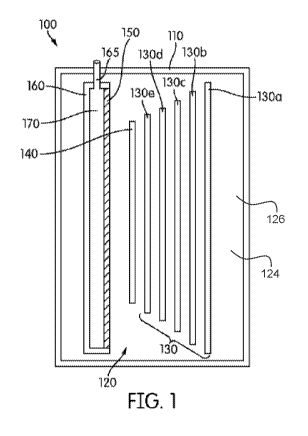
[0010] Figure 1 depicts a schematic view of an electrochemical cell having an
immersed oxidant reduction electrode.
[0011] Figure 2 depicts a schematic view of an electrochemical cell having an
oxidant reduction electrode which defines a boundary wall for the
electrochemical
cell.
3
CA 03031513 2019-01-21
WO 2018/018036
PCT/US2017/043489
[0012] Figure 3 shows a side perspective view of an exemplary
electrochemical cell having a scrubber module that is detached from the cell
housing.
[0013] Figure 4 shows a side view of an exemplary electrochemical cell
having a scrubber module that is removed and a bypass adapter configured from
the
inflow port to the outflow port.
[0014] Figure 5 shows a side view of an exemplary electrochemical cell
having a scrubber module that is attached to the cell housing.
[0015] Figure 6 shows a top view of an exemplary electrochemical cell having
a moisture management system comprising a recirculation valve and scrubber.
[0016] Figure 7 shows a top perspective view of an exemplary electrochemical
cell having a moisture management system.
[0017] Figure 8 shows a top perspective view of an exemplary electrochemical
cell having a control system.
[0018] Figure 9 shows an exemplary outflow bypass conduit within the
manifold portion of the electrochemical cell.
[0019] Figure 10 shows an exploded view of an exemplary scrubber having a
heating element.
[0020] Figure 11 shows a cross-sectional schematic of an exemplary
electrochemical cell having a moisture and carbon dioxide management system.
[0021] Figure 12 shows a block diagram of a water management system.
DETAILED DESCRIPTION OF THE ILLUSTRATED EMBODIMENTS
[0022] Corresponding reference characters indicate corresponding parts
throughout the several views of the figures. The figures represent an
illustration of
some of the embodiments of the present disclosure and are not to be construed
as
limiting the scope of the disclosure in any manner. Further, the figures are
not
necessarily to scale, some features may be exaggerated to show details of
particular
components. Therefore, specific structural and functional details disclosed
herein are
not to be interpreted as limiting, but merely as a representative basis for
teaching
one skilled in the art to variously employ the present invention.
4
CA 03031513 2019-01-21
WO 2018/018036
PCT/US2017/043489
[0023] As used herein, the terms "comprises," "comprising," "includes,"
"including," "has," "having" or any other variation thereof, are intended to
cover a
non-exclusive inclusion. For example, a process, method, article, or apparatus
that
comprises a list of elements is not necessarily limited to only those elements
but may
include other elements not expressly listed or inherent to such process,
method,
article, or apparatus. Also, use of "a" or "an" are employed to describe
elements
and components described herein. This is done merely for convenience and to
give
a general sense of the scope of the disclosure. This description should be
read to
include one or at least one and the singular also includes the plural unless
it is
obvious that it is meant otherwise.
[0024] Certain exemplary embodiments of the present disclosure are
described herein and are illustrated in the accompanying figures. The
embodiments
described are only for purposes of illustrating the present disclosure and
should not
be interpreted as limiting the scope of the disclosure. Other embodiments of
the
disclosure, and certain modifications, combinations and improvements of the
described embodiments, will occur to those skilled in the art and all such
alternate
embodiments, combinations, modifications, improvements are within the scope of
the present disclosure.
[0025] An exemplary moisture and carbon dioxide system in accordance with
embodiments of this disclosure may comprise a recirculation mechanism wherein
at
least a portion of the air exiting the electrochemical cell is recirculated
back into the
air inflow to the cell. Many electrochemical cells produce heat and an exhaust
flow
that is high in humidity and therefore conserving this moisture through
recirculation
can effectively conserve the moisture in the system.
[0026] An exemplary moisture and carbon dioxide management system in
accordance with embodiments of this disclosure comprises a humidity exchange
membrane (HEM), for transfer of moisture from the outflow of air from a
chamber
containing the air breathing electrode of the electrochemical cell to the air
inflow of
said chamber. The HEM comprises a moisture exchange material, such as a
membrane comprising an ionomer, such as perfluorosulfonic acid polymer, for
example. A HEM separates air inflow to the cell from air exiting the
electrochemical
cell, such as from the oxidant reduction electrode air chamber, whereby
moisture
from the air exiting the cell is transferred through the humidity exchange
membrane
CA 03031513 2019-01-21
WO 2018/018036
PCT/US2017/043489
to the air inflow due to a relative humidity (RH) difference across the
membrane (air
oufflow at high RH, air inflow at low RH). The air exiting the oxidant
reduction
electrode air chamber, or air chamber outflow, is warm and humid and therefore
can
carry a relatively high amount of moisture which enables the HEM to work
effectively.
This exiting air picks up moisture from the liquid ionically conductive medium
as it
flows through the cell and is heated due to the increased heat from the
chemical
reactions. The air chamber outflow may be hotter and contain a relatively high
moisture content. For example, the air chamber outflow may be 10 C, 20 C, 30
C,
or 40 C hotter than the air inflow. The electrochemical reactions within the
cell heat
the air chamber and also humidify the air chamber air. For example, the air
chamber
oufflow may have a relative humidity of more than about 70%, more than about
80%,
more than about 90%, more than about 95%, and substantially fully saturated,
depending on the flow rates, size of the system and environmental conditions.
As
an example, air inflow may be very dry, at only 20% relative humidity at 30 C
and
may pass by a HEM module having air chamber outflow on the opposing side of
the
HEM at 90% relative humidity at 50 C, to increase the air inflow humidity to
about
70% before entering the cell. A HEM may be configured in a module comprising
multiple layers, folds, pleats or corrugations of the HEM to increase the
amount of
surface area that the air stream must flow over, thereby increase the amount
of
moisture transferred. In accordance with an embodiment, a marketed or
manufactured HEM or HEM module may be used. An exemplary HEM or HEM
module is available from DPoint Technologies, Vancouver, BC, Canada, for
example, and may be used in the disclosed system. However, this example is not
intended to be limiting.
[0027] An exemplary moisture and carbon dioxide management system in
accordance with embodiments of this disclosure comprises a recirculation
feature,
such as a valve or other mechanism, that may be configured to reintroduce some
of
the air chamber outflow directly back into the air inflow, thereby increasing
the
moisture level of the air inflow. When an electrochemical cell is located in a
very arid
environment, recirculation of the outflow air into the air inflow can
effectively
conserve moisture in the system. A recirculation feature may be configured
upstream, prior to the inflow air reaching the HEM, or downstream of the HEM.
In
one embodiment, it may be preferred to locate a recirculation feature upstream
of the
6
CA 03031513 2019-01-21
WO 2018/018036
PCT/US2017/043489
HEM, whereby the outflow air flows past the HEM, thereby maintaining the HEM
in a
warm moist state, prior to recirculation. As described herein, in some
embodiments,
a HEM may work more effectively when maintained in a warm and moist condition.
A recirculation feature may be a valve that is operated by a control system or
may be
a baffle that is automatically controlled by pressure. A control system may
monitor
the moisture level within and external to the system, such as relative
humidity, RH, of
the air inflow, the air outflow, the ambient RH, the liquid electrolyte level
and the like
to determine when and how much recirculation to include into the air inflow.
The air
exiting the oxidant reduction electrode air chamber, or air chamber outflow,
is warm
and humid and a portion or amount thereof may be recirculated into the air
inflow. In
one embodiment, a valve is opened and closed to control when the air chamber
oufflow is recirculated and what portion or amount is recirculated. For
example, in
very arid environments, a high proportion of the air chamber outflow may be
recirculated, such as about 40% or more, about 50% or more, about 70% or more,
about 90% or more, or all of the air chamber outflow or any portion between
and
including the percentages provided. The remaining air chamber outflow may be
passed through the air flow device and out of the cell.
[0028] For example, in one embodiment, an exemplary electrochemical cell
may utilize a recirculation feature that provides about 50% of the inflow to
the cell
from air outflow from the cell. The ambient air, or inlet air may comprise
about
400ppm carbon dioxide, 50% RH, and 21.2% oxygen. The air outflow from the cell
may have a reduced carbon dioxide concentration, such as about 0%, due to the
scrubber and/or reaction within the cell, 100% RH, and a reduced oxygen
concentration of about 12%. When the ambient air and air outflow from the cell
are
mixed through the recirculation feature the inlet airflow to the cell will
have a 200ppm
carbon dioxide concentration, about 75% RH, and 18% oxygen. The
electrochemical
cell may be configured to run at a three or four stoichiometry for oxygen and
therefore a slightly reduced oxygen concentration will not create a loss of
power
generation potential. In addition, there will be a large benefit from the
increase
humidity level and reduced carbon dioxide level which will result in extending
the life
of the electrochemical cell.
[0029] An exemplary moisture and carbon dioxide management system in
accordance with embodiments of this disclosure comprises a mist elimination
system
7
CA 03031513 2019-01-21
WO 2018/018036
PCT/US2017/043489
that may be incorporated to control the loss of liquid ionically conductive
medium,
such as an electrolyte. A mist elimination system may comprise a baffle or
valve, a
filter, a hydrogen recombination catalyst, a neutralizer and a hydrophobic
filter. An
exemplary mist elimination system reacts hydrogen to form water that may be
drained back into the electrochemical cell. Gasses produced during normal cell
operation, such as for a metal-air cell during self-discharge or cell charge,
rise to the
surface of the electrolyte as bubbles which burst at the electrolyte surface.
The
action of the bursting bubble generates a fine mist of electrolyte which will
leave the
cell with the effluent gas stream. An exemplary mist elimination filter is
placed in this
gas stream to recapture this electrolyte mist and return it to the liquid
electrolyte.
[0030] The operational relative humidity ranges, or humidity ranges within the
air chamber, may depend on the particular ionically conductive medium, in
addition
to the temperature of ambient air and the cell, for example. It may be
appreciated
that aqueous salt electrolytes, e.g., potassium hydroxide, may be
characterized as
hygroscopic. For example, for a cell comprising an aqueous KOH electrolyte, a
relative humidity less than ca. 50% may result in water loss through the
oxidant
reduction electrode, or air electrode. An ambient relative humidity greater
than 80%
(or greater than ca. 80%) may result in water uptake into the cell through the
oxidant
reduction electrode, or air electrode. Water release through the air electrode
may
occur at greater relative humidity than ca. 50% in an air temperature range of
50
degrees Celsius to 80 degrees Celsius. A relative humidity from 50%
(inclusive) to
80% (inclusive), or in a mid-range, may be characterized as neutral. For
example, at
70% relatively humidity into the cell, 250 ml of water may be lost at 50
degrees C,
and only 15 ml (which is considered negligible in a cell having 8 liters total
volume) is
lost at 25 degrees C. It should be appreciated that the ranges may also and/or
alternatively change depending on the ionically conductive medium and its
hygroscopic/hygrophobic characteristics.
[0031] A variety of water management techniques are described herein and
may be used with the disclosed system. U.S. Patent Application No. 15/077,341,
to
Fluidic Inc., filed on March 22, 2016, entitled Water Management System In
Electrochemical Cells with Vapor Return Comprising Air Electrodes describes
some
other water management systems and techniques and is incorporated, in its
entirety,
by reference herein.
8
CA 03031513 2019-01-21
WO 2018/018036
PCT/US2017/043489
[0032] An exemplary moisture and carbon dioxide management system in
accordance with embodiments of this disclosure comprises a scrubber module for
removing carbon dioxide, 002, from the air inflow to the cell. Some exemplary
scrubber media, such as soda-lime, requires some moisture to react with the
carbon
dioxide. The scrubber media may absorb some moisture from the air inflow. This
absorbed moisture may be reintroduced to the cell by heating of the scrubber.
Heating may be passive heating, wherein heat generated from the cell is used
to
heat the scrubber, or a dedicated resistive heater element may be used to heat
the
scrubber.
[0033] An exemplary scrubber system operates more effectively when the
incoming air to the scrubber is humidified and therefore receiving inflow air
to the
scrubber after passing through the HEM may improve overall system
effectiveness.
The scrubber may absorb some of the moisture from the airflow therethrough,
and
this absorbed moisture may be reintroduced to the cell by heating the
scrubber.
Heating may be passive heating, wherein heat generated from the cell is used
to
heat the scrubber, or a dedicated resistive heater element, controlled by the
controller, may be used to heat the scrubber. In the case of passive heating,
heat
from the electrochemical cell may be conducted to the scrubber module and
specifically to the scrubber media. Conductive elements may be configured to
increase the amount of heating that his conducted to the scrubber media. In
the
case of active heating, an electrically resistive heating element is
configured to heat
the scrubber and/or scrubber media. Electrical current generated by the
electrochemical cell may be passed through the electrically resistive heating
element
continuously or it may be turned on and off by a switch that is activated by
the
control system. Again, the control system may receive input values from one or
more sensors that are used to activate the heating of the scrubber heater. In
an
exemplary embodiment, the electrochemical cell may be configured to run the
airflow
device even when the electrochemical cell is not operating to produce power,
and
thereby absorb moisture from the environment in the scrubber media which may
be
subsequently desorbed, or driven out of the scrubber media and into the
electrochemical cell. For example, the control system may subsequently heat
the
scrubber media to drive off absorbed moisture from the scrubber media.
9
CA 03031513 2019-01-21
WO 2018/018036
PCT/US2017/043489
[0034] An exemplary scrubber comprises scrubber media that is reversible or
irreversible. A reversible scrubber media may be reactivated by heating, for
example, wherein the absorbed carbon dioxide is desorbed and driven off from
the
scrubber media. A reversible scrubber material may be reactivated by heating
to
about 70 C or more, or about 90 C or more. Therefore, a scrubber module that
is
configured to be heated to drive off absorbed moisture may also be reactivated
when
comprising a reversible scrubber media. When irreversible scrubber media
reacts
with the carbon dioxide it is changed chemically and is consumed. Scrubber
media,
irreversible or reversible, may be purged periodically to regulate the
humidity level
and in the case of reversible media, to drive off the absorbed carbon dioxide.
A
purge cycle may be run while a reversible scrubber media is heated to more
effectively purge the desorbed carbon dioxide from the system. During a
scrubber
purge cycle, a flow of air through the scrubber may be reversed, wherein the
air flow
device, such as a fan, is reversed and therefore pushes air through the cell
into the
scrubber and out of the air inlet. In addition, the rate of flow of air
through the
scrubber may be increased, wherein the flow rate is higher, such as at least
two
times, three times, five times, ten times or more higher than a standard
operational
flow rate. This may be accomplished by increasing the fan speed, for example.
In
still another embodiment, a valve enables air to flow through the scrubber and
then
directly out of the outlet of the system without passing through the cell
housing,
and/or without passing by the HEM after it exits the scrubber.
[0035] A scrubber media may comprise media or material(s) selected from the
group of: soda lime, sodium hydroxide, potassium hydroxide, and lithium
hydroxide,
lithium peroxide, calcium oxide, serpentinite, magnesium silicate, magnesium
hydroxide, olivine, molecular sieves, amines, and monoethanolamine, and/or
derivatives and/or combinations thereof. Amine scrubber media is reversible
whereas soda lime is irreversible.
[0036] A scrubber configured to remove carbon dioxide from an air inflow to a
metal-air electrochemical cell is described in U.S. Patent Application Serial
No.
15/077,341, to Fluidic Inc., filed on March 22, 2016, entitled Water
Management
System In Electrochemical Cells with Vapor Return Comprising Air Electrodes
and
currently pending; the entirety of which is hereby incorporated by reference
herein.
CA 03031513 2019-01-21
WO 2018/018036
PCT/US2017/043489
[0037] Various portions of the electrochemical cell 100 may be of any suitable
structure or composition, including but not limited to being formed from
plastic, metal,
resin, or combinations thereof. Accordingly, the cell 100 may be assembled in
any
manner, including being formed from a plurality of elements, being integrally
molded,
or so on. In various embodiments the cell 100 and/or the housing 110 may
include
elements or arrangements from one or more of U.S. Patent Nos. 8,168,337,
8,309,259, 8,491,763, 8,492,052, 8,659,268, 8,877,391, 8,895,197, 8,906,563,
8,911,910, 9,269,996, 9,269,998 and U.S. Patent Application Publication Nos.
20100316935, 20110070506, 20110250512, 20120015264, 20120068667,
20120202127, 20120321969, 20130095393, 20130115523, and 20130115525, each
of which are incorporated herein in their entireties by reference.
[0038] FIG. 1 illustrates a schematic cross sectional view of an
electrochemical cell 100. As shown, the components of the electrochemical cell
100
may be contained at least partially in an associated housing 110. The cell 100
utilizes a liquid ionically conductive medium 124, such as an electrolyte 126,
that is
contained within the housing 110, and is configured to circulate therein to
conduct
ions within the cell 100. While at times the ionically conductive medium may
be
generally stationary within the housing 110, such as in a stagnant zone, it
may be
appreciated that the cell 100 may be configured to create a convective flow of
the
ionically conductive medium. In some embodiments, the flow of the ionically
conductive medium may be a convective flow generated by bubbles of evolved gas
in the cell 100, such as is described in U.S. Patent Application Ser. No.
13/532,374
incorporated above in its entirety by reference.
[0039] Although in the illustrated embodiment of FIG. 1 the cell housing is
configured such that the oxidant reduction electrode 150 is immersed with the
oxidant reduction electrode module 160 into the cell chamber 120, it may be
appreciated that in various embodiments, other configurations or arrangements
of
the cell 100 are also possible. For example, in FIG. 2, another embodiment of
the
cell 100 (specifically, cell 100*) is presented, whereby an oxidant reduction
electrode
150* defines a boundary wall for the cell chamber 120, and is sealed to a
portion of a
housing 110* so as to prevent or substantially prevent seepage of ionically
conductive medium therebetween. In some cases, however, such a configuration
is
generally not preferred, however, due to concerns that a failure of the
oxidant
11
CA 03031513 2019-01-21
WO 2018/018036
PCT/US2017/043489
reduction electrode 150* would result in leakage of the ionically conductive
medium
out of the cell 100*. Regardless, in some such embodiments the convective flow
of
the ionically conductive medium in the cell chamber 120, described in greater
detail
below, may be in a direction upwards and away from the oxidant reduction
electrode
150*, across the top of the fuel electrode 130.
[0040] As shown in FIG. 3, an exemplary electrochemical cell 100 has a
scrubber module 60 that is detachably attachable to the cell housing 110. The
scrubber module may be detached from the electrochemical cell while the
electrochemical cell is running. Since air is drawn in to the cell by an
airflow device,
removal of the scrubber module still allows air to enter into the inflow port
65. This
allows for removal of the scrubber module for maintenance or replacement
without
interfering with the operation of the electrochemical cell. In normal
operation with the
scrubber attached, air is drawn in through the air intake 40, into the
scrubber through
the outflow port 61 and into the inlet port of the scrubber 62. The air then
exits the
scrubber through the outlet port of the scrubber 64 and enters back into the
cell
housing through the inflow port 65. Air passes from the air inflow port 65
into the air
chamber of the oxidant reduction electrode (not shown). A cover 111 is
configured
over the top of the electrochemical cell housing 110, or over the cell
manifold
assembly 114. The cover and manifold assembly help to protect the cell
components from the elements and keep dust, rain and other environmental
elements out. An exhaust vent 45 is configured as an outlet for gas venting
from
the interior chamber of the cell.
[0041] As shown in FIG. 4, the scrubber module 60 is detached from the
electrochemical cell 100 and a bypass adapter 77 extends from the outflow port
61
to the inflow port 65. Incoming airflow passes through the outflow port 61,
into the
oufflow port end 79 of the bypass adapter, through the bypass adapter 77, out
of the
cell inflow end 78 of the bypass adapter and into the inflow port 65. The
bypass
adapter allows humid air inflow into the cell, when a HEM is utilized, while
the
scrubber is removed. The bypass adapter enables the cell to operate without
the
scrubber without any excessive moisture loss. The bypass adapter shown is a
physical connector having an auxiliary conduit for passing inflow air into the
inflow
port. It is to be understood that this bypass flow may be accomplished through
an
12
CA 03031513 2019-01-21
WO 2018/018036
PCT/US2017/043489
inlet bypass conduit, configured as part of the cell, along with a valve to
open flow up
to an inlet bypass conduit, as shown in FIG. 12.
[0042] As shown in FIG. 5, the scrubber module 60 is attached to the outflow
port 61 and inflow port 65 of the manifold assembly 114. The terminals of the
cell 44
are shown extending from the manifold assembly 114.
[0043] Referring now to FIGS. 6 to 8, an exemplary electrochemical cell 100
has a moisture management system 59 comprising a humidity exchange membrane
module 50, recirculation feature 70, such as a valve or baffle, and scrubber
60.
Ambient air enters the cell through the air intake 40 and is passed along the
inflow
side 51 of the HEM where it picks up moisture from the air flowing along the
outflow
side 52 of the HEM. The air then flows through the outflow port 61 and into
the
scrubber module 60 through the inlet port of the scrubber. The air then flows
through the scrubber media, wherein carbon dioxide is removed from the
airflow.
The air then flows back into the cell housing 110 and into the cathode inlet
41, and
subsequently into the oxidant reduction electrode air chamber. The air flows
through
the air chamber and out of the air chamber outlet 42, or cathode outlet, which
is on
an opposing end of the cell housing from the cathode inlet. The air then flows
through an outflow bypass conduit that extends along the bottom of the
manifold
assembly 114. Air flows into the bypass inlet 47, through the outflow bypass
conduit
(not shown), and out of the bypass outlet 49. The airflow then flows over the
outflow
side 52 of the HEM. Some of the airflow may be diverted through a
recirculation
valve 70 back into the air inflow. The remainder of the air is drawn through
the
airflow device 56 and out of the cell housing. The cell terminals 44 are shown
extending from the top of the cell housing 110. A plurality of sensor leads 46
are
shown extending from the top of the electrochemical cell 100. As described
herein,
the sensor leads may measure the level of the electrolyte, and/or the humidity
level
of the air chamber. A control system 102, as shown in FIG. 8 may receive input
from
the sensor leads and open, close or adjust the amount of flow through the
recirculation feature, or valve. The control system may change the amount of
flow
being drawn into the system and may draw air through the system even when the
cell is not operating to produce power. The moisture in the air being drawn
through
the scrubber may be absorbed by the scrubber media and retained for later use,
wherein the scrubber is heated either passively or actively by the system. The
13
CA 03031513 2019-01-21
WO 2018/018036
PCT/US2017/043489
exemplary control system shown in FIG. 8 comprises a control circuit 104 and a
microprocessor 106. The control system is configured on top of the manifold
assembly 114 and a cover 111, as shown in FIG. 5, extends over the control
system
102.
[0044] As shown in FIG. 9, the outflow bypass conduit 48 extends under the
manifold assembly 114. Air exiting the air chamber is diverted into the bypass
inlet
47 and flows through the conduit to the bypass outlet 49. The air then flows
into the
HEM 50 or a portion is diverted into the inflow air through the recirculation
feature.
The air chamber extends across a portion of the length of the cell housing.
[0045] As shown in FIG. 10, a scrubber module 60 may comprise a heating
element 69 that is configured to be coupled with the control system to heat
the
scrubber media 66. The scrubber media as shown is a reversible scrubber media
67, a scrubber media that absorbs carbon dioxide that may be driven off by
increasing the temperature of the reversible scrubber media. The heating
element
69 extends within the scrubber module housing 68 to provide effective heating
of the
scrubber media, but may be configured on an exterior surface of the housing. A
heater connector enables the heating element to be easily coupled with the
control
system when the scrubber module is attached to the cell housing. The control
system may turn on the heating elements and control the valves within the
electrochemical cell to control flow through the scrubber while being heated
to
effectively remove the carbon dioxide from the scrubber media.
[0046] As shown in FIG. 11, air flows into the manifold assembly 114 of the
electrochemical cell 100, through the scrubber 60 and then into the air
chamber 170.
As shown, air enters the air chamber 170 configured within the interior
chamber 122
of the cell housing 110. The air flows across the air chamber and exits the
interior
chamber where it enters the outflow bypass conduit 48. A pressure relief valve
94 is
configured to vent pressure from within the cell chamber 120 when exceeding a
threshold limit. Also shown in FIG. 11 is a mist elimination system 80 that is
configured to reduce and/or eliminate mist that evolves from the surface of
the
electrolyte due to bubbling of gasses to the surface and to prevent or
substantially
prevent leakage of the electrolyte 126 in the event of an upset. The mist
eliminator
system comprises a safety vent 82 that is in communication with the interior
chamber
122 of the cell housing 110, and therefore exposed to the ionically conductive
14
CA 03031513 2019-01-21
WO 2018/018036
PCT/US2017/043489
medium 124 and/or gas space there above. An exemplary safety vent provides a
tortuous conduit path that will slow the transfer of any liquid electrolyte to
the
downstream portions of the mist eliminator system. Another exemplary safety
vent
comprises a ball valve that allows air to go around the ball due to a pressure
differential when upright, and when upset, seals when the ionically conductive
media
liquid forces the ball against a seat to prevent or substantially prevent
liquid loss. A
filter 84 is configured downstream of the safety vent and may be a concave
filter that
will drain absorbed ionically conductive medium back into the anode chamber,
as
described in U.S. Patent No. 9,269,998, incorporated by reference herein.
[0047] The exemplary mist elimination system 80 comprises a hydrogen
recombination portion 86, comprising a hydrogen recombination catalyst that
reacts
with any hydrogen to form water. The catalyst may be configured on a support
material such as particles or surfaces of the mist elimination system that are
exposed to the gas exiting the cell housing from the anode space. Air may
enter in
to the mist elimination system through the hydrophobic filter 98 to provide
the
necessary oxygen for the hydrogen recombination reaction. The hydrophobic
filter
may prevent or substantially prevent water ingress into the electrochemical
cell.
[0048] The exemplary mist elimination system comprises a neutralizer portion
90 comprising a neutralizer media 91, such as an acid, configured to
neutralize the
ionically conductive medium. For example, the ionically conductive medium may
comprise a potassium hydroxide solution that is caustic, and a neutralizer may
be a
solid acid or acid on carbon or some other support material. The neutralizer
is
configured to reduce any reactive gases that may exhaust from the anode
chamber
or the chamber containing the ionically conductive medium.
[0049] FIG. 12 shows a block diagram of an exemplary moisture (water)
management system 59, and a carbon dioxide management system 13. The two
systems may work in tandem to conserve moisture and provide a carbon dioxide
depleted inflow stream to the electrochemical cell. The moisture management
system increases the humidity of inflow air by drawing moisture from the
outflow
exhaust of the cell, which is typically warm and humid, when the cell is
operating.
The HEM module 50 has an inflow side 51 and an outflow side 52 separated by a
HEM 54. The moisture level and carbon dioxide level of inflow air may further
be
adjusted by recirculating at least a portion of the outflow through a
recirculation
CA 03031513 2019-01-21
WO 2018/018036
PCT/US2017/043489
feature 70, such as a valve or baffle. As shown, the recirculation feature is
upstream, prior to the inflow air reaching the HEM. Recirculated outflow will
have a
relative high moisture content and a lower carbon dioxide concentration than
ambient air, in most cases. The moisture management system also incorporates a
scrubber 60, wherein the scrubber media absorbs moisture from the air inflow.
Scrubber media works more effectively when properly hydrated. In addition, the
absorbed moisture in the scrubber media may be periodically desorbed and
passed
into the electrochemical cell chamber 120, and subsequently through the rest
of the
moisture management system. The moisture management system further
comprises an inflow bypass conduit 75 and valve 76. The control system 102,
comprising a microprocessor 106 may open and close valves, including the
inflow
bypass valve and or a recirculation valve 72 to efficiently operate the system
and
conserve moisture. For example, the scrubber may be detached and the
controller
may divert inflow air through the bypass conduit to the inflow port 65 of the
cell
chamber 120.
[0050] It will be apparent to those skilled in the art that various
modifications,
combinations and variations can be made in the present disclosure without
departing
from the spirit or scope of the disclosure. Specific embodiments, features and
elements described herein may be modified, and/or combined in any suitable
manner. Thus, it is intended that the present disclosure cover the
modifications,
combinations and variations of this disclosure provided they come within the
scope
of the appended claims and their equivalents.
16